Engine oil service MITSUBISHI 380 2005 Workshop Manual
[x] Cancel search | Manufacturer: MITSUBISHI, Model Year: 2005, Model line: 380, Model: MITSUBISHI 380 2005Pages: 1500, PDF Size: 47.87 MB
Page 849 of 1500
ON-VEHICLE SERVICE
HEATER, AIR CONDITIONING AND VENTILATION55-148
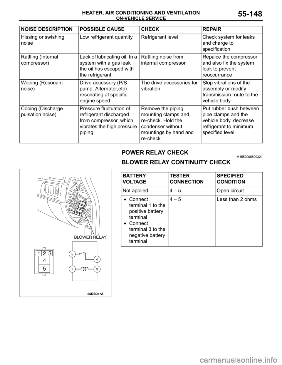
POWER RELAY CHECKM1552008800321
BLOWER RELAY CONTINUITY CHECK
Hissing or swishing
noiseLow refrigerant quantity Refrigerant level Check system for leaks
and charge to
specification
Rattling (Internal
compressor)Lack of lubricating oil. In a
system with a gas leak
the oil has escaped with
the refrigerantRattling noise from
internal compressorRepalce the compressor
and also fix the system
leak to prevent
reoccurrance
Wooing (Resonant
noise)Drive accessory (P/S
pump, Alternator,etc)
resonating at specific
engine speedThe drive accessories for
vibrationStop vibrations of the
assembly or modify
transmission route to the
vehicle body
Cooing (Discharge
pulsation noise)Pressure fluctuation of
refrigerant discharged
from compressor, which
vibrates the high pressure
pipingRemove the piping
mounting clamps and
re-check. Hold the
condenser without
mountings by hand and
re-checkPut rubber bush between
pipe clamps and the
vehicle body. decrease
refrigerant to minimum
specified level. NOISE DESCRIPTION POSSIBLE CAUSE CHECK REPAIR
BATTERY
VOLTAGETESTER
CONNECTIONSPECIFIED
CONDITION
Not applied 4
5 Open circuit
Connect
terminal 1 to the
positive battery
terminal
Connect
terminal 3 to the
negative battery
terminal4
5 Less than 2 ohms
Page 919 of 1500
ENGINE COOLING DIAGNOSIS
ENGINE COOLING14-4
INSPECTION PROCEDURE 2: Engine Overheating
DIAGNOSIS
STEP 1. Remove the radiator cap and check for coolant
contamination.
Q: Is the coolant contaminated with rust and oil?
YES : Replace it. Refer to P.14-27.
NO : There is no action to be taken. Go to Step 2.
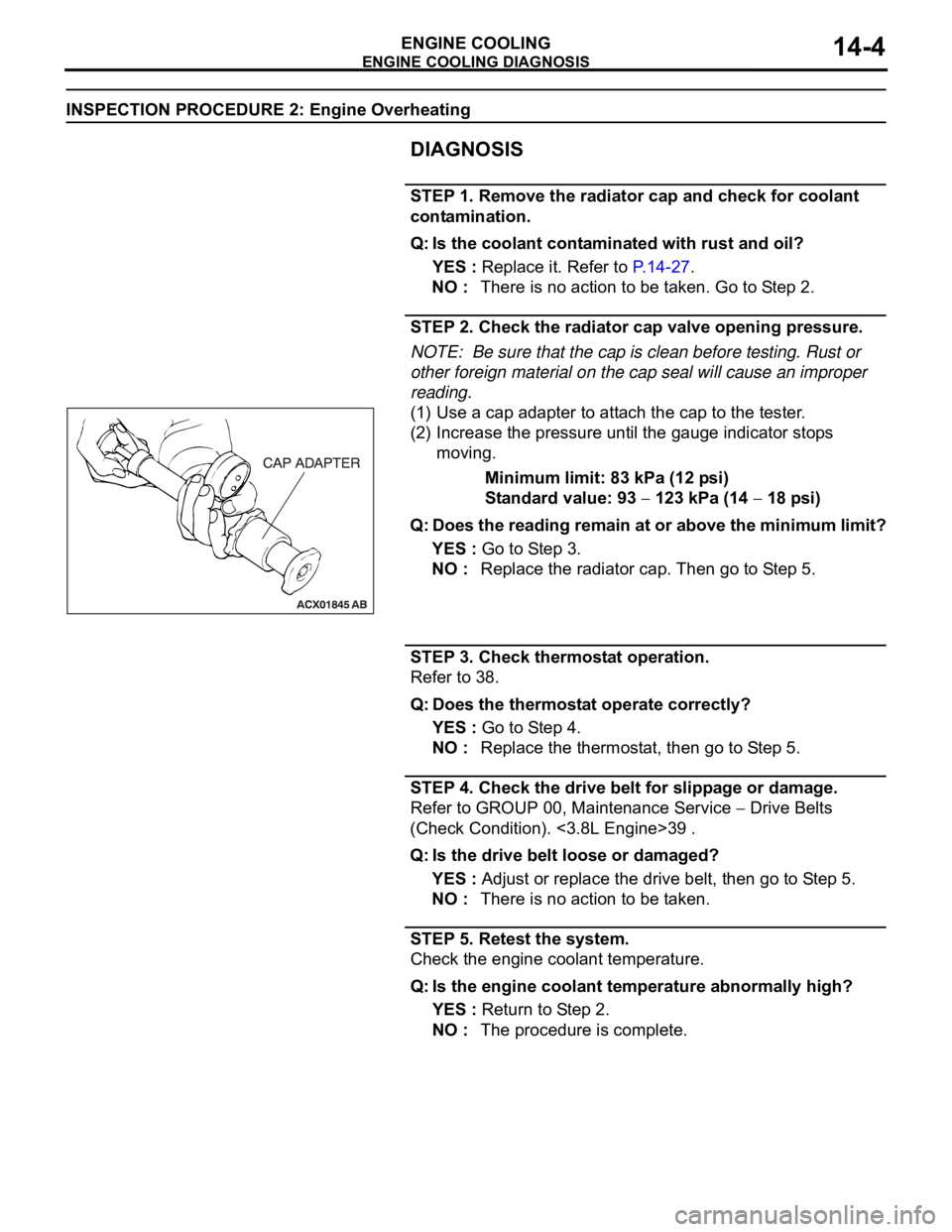
STEP 2. Check the radiator cap valve opening pressure.
NOTE: Be sure that the cap is clean before testing. Rust or
other foreign material on the cap seal will cause an improper
reading.
(1) Use a cap adapter to attach the cap to the tester.
(2) Increase the pressure until the gauge indicator stops
moving.
Minimum limit: 83 kPa (12 psi)
Standard value: 93
123 kPa (14 18 psi)
Q: Does the reading remain at or above the minimum limit?
YES : Go to Step 3.
NO : Replace the radiator cap. Then go to Step 5.
STEP 3. Check thermostat operation.
Refer to 38.
Q: Does the thermostat operate correctly?
YES : Go to Step 4.
NO : Replace the thermostat, then go to Step 5.
STEP 4. Check the drive belt for slippage or damage.
Refer to GROUP 00, Maintenance Service
Drive Belts
(Check Condition). <3.8L Engine>39 .
Q: Is the drive belt loose or damaged?
YES : Adjust or replace the drive belt, then go to Step 5.
NO : There is no action to be taken.
STEP 5. Retest the system.
Check the engine coolant temperature.
Q: Is the engine coolant temperature abnormally high?
YES : Return to Step 2.
NO : The procedure is complete.
Page 947 of 1500
RADIATOR
ENGINE COOLING14-32
RADIATOR
REMOVAL AND INSTALLATIONM1141001500521
Pre-removal Operation
Engine Coolant Draining (Refer to 27).
Air Cleaner Removal (Refer to GROUP 15, Air Cleaner 4).Post-installation Operation
Air Cleaner Installation (Refer to GROUP 15 4).
Engine Coolant Refilling and Level Check (Refer to 27).
A/T Fluid Refilling and Level Check (Refer to GROUP 00,
Maintenance Service 45).
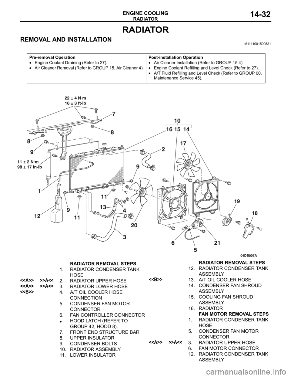
RADIATOR REMOVAL STEPS
1. RADIATOR CONDENSER TANK
HOSE
<> >>A<<2. RADIATOR UPPER HOSE
<> >>A<<3. RADIATOR LOWER HOSE
<>4. A/T OIL COOLER HOSE
CONNECTION
5. CONDENSER FAN MOTOR
CONNECTOR
6. FAN CONTROLLER CONNECTOR
HOOD LATCH (REFER TO
GROUP 42, HOOD 8).
7. FRONT END STRUCTURE BAR
8. UPPER INSULATOR
9. CONDENSER BOLTS
10. RADIATOR ASSEMBLY
11. LOWER INSULATOR12. RADIATOR CONDENSER TANK
ASSEMBLY
<>13. A/T OIL COOLER HOSE
14. CONDENSER FAN SHROUD
ASSEMBLY
15. COOLING FAN SHROUD
ASSEMBLY
16. RADIATOR
FAN MOTOR REMOVAL STEPS
1. RADIATOR CONDENSER TANK
HOSE
5. CONDENSER FAN MOTOR
CONNECTOR
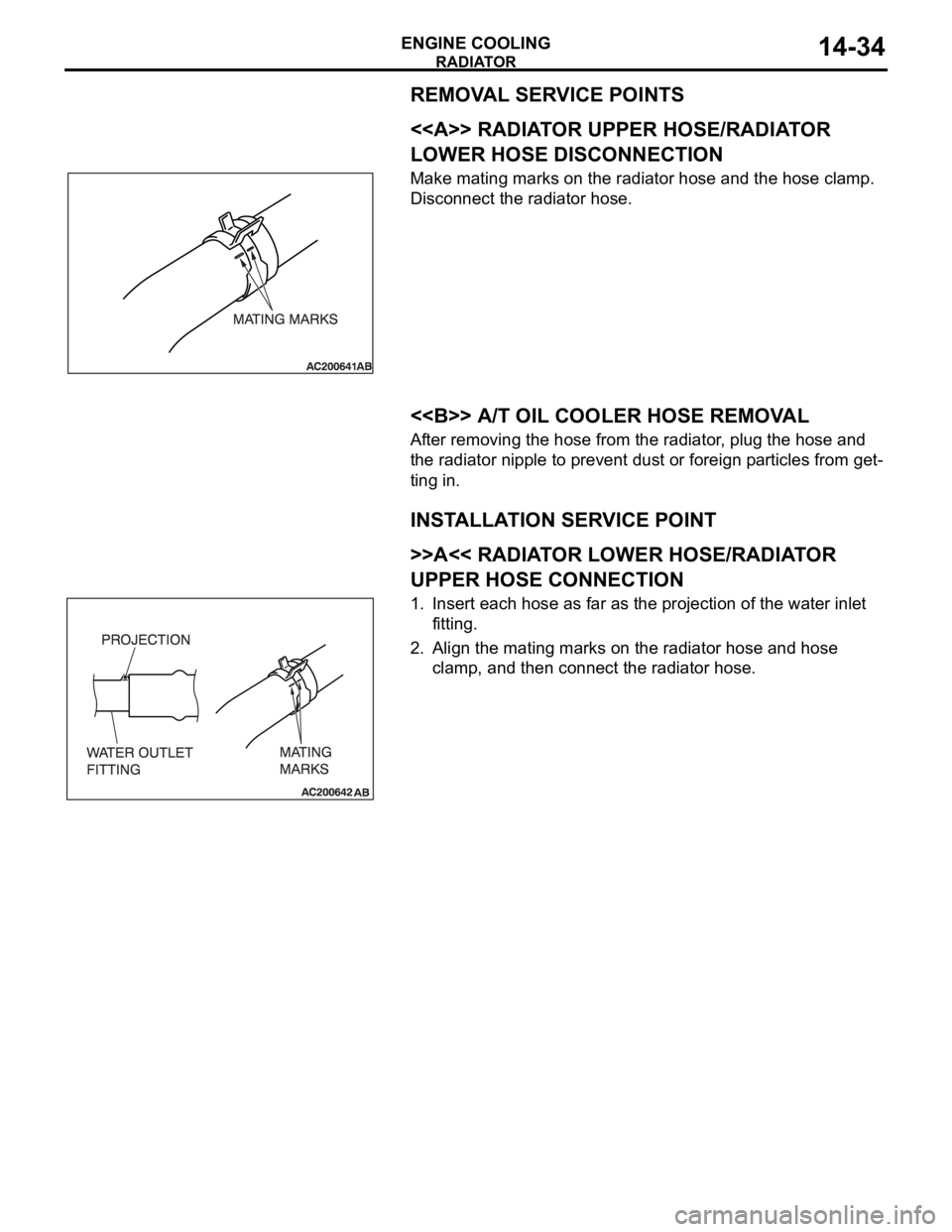
<> >>A<<3. RADIATOR UPPER HOSE
6. FAN MOTOR CONNECTOR
12. RADIATOR CONDENSER TANK
ASSEMBLY RADIATOR REMOVAL STEPS
Page 949 of 1500
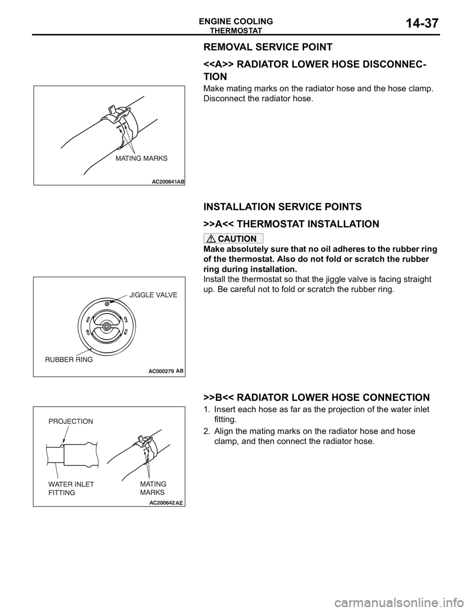
Page 952 of 1500
Page 954 of 1500
WATE R P U M P
ENGINE COOLING14-39
WAT E R P U M P
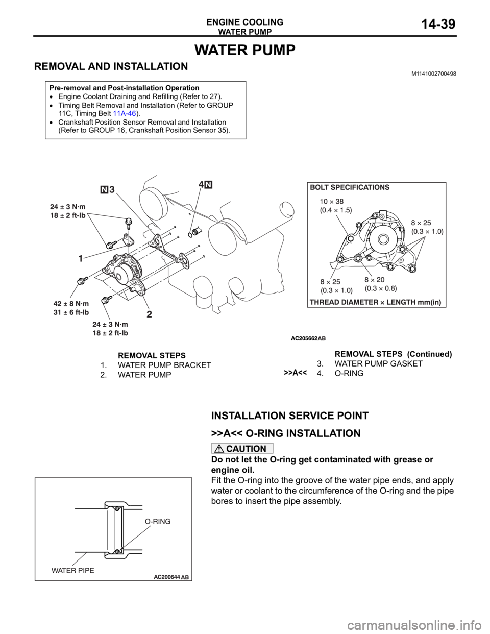
REMOVAL AND INSTALLATIONM1141002700498
INSTALLATION SERVICE POINT
.
>>A<< O-RING INSTALLATION
Do not let the O-ring get contaminated with grease or
engine oil.
Fit the O-ring into the groove of the water pipe ends, and apply
water or coolant to the circumference of the O-ring and the pipe
bores to insert the pipe assembly.
Pre-removal and Post-installation Operation
Engine Coolant Draining and Refilling (Refer to 27).
Timing Belt Removal and Installation (Refer to GROUP
11C, Timing Belt 11A-46).
Crankshaft Position Sensor Removal and Installation
(Refer to GROUP 16, Crankshaft Position Sensor 35).
REMOVAL STEPS
1. WATER PUMP BRACKET
2. WATER PUMP3. WATER PUMP GASKET
>>A<<4. O-RINGREMOVAL STEPS (Continued)
Page 956 of 1500
WATER HOSE AND WATER PIPE
ENGINE COOLING14-41
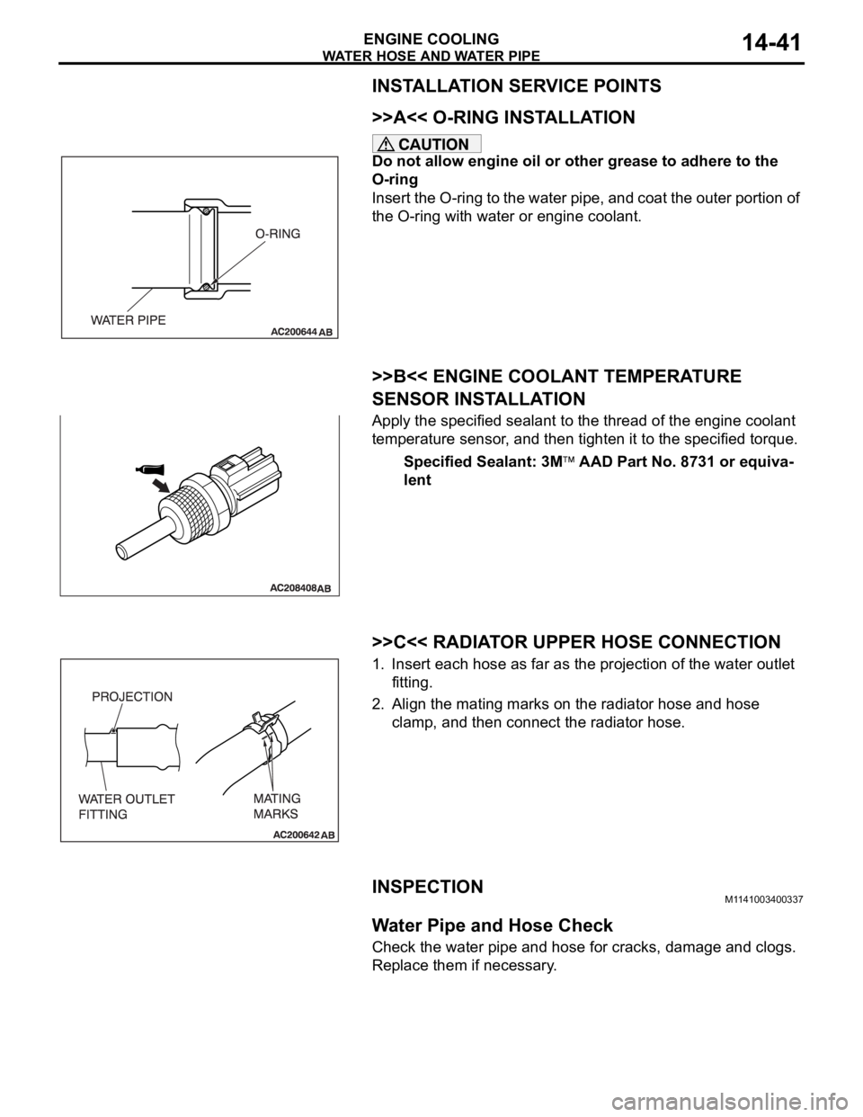
INSTALLATION SERVICE POINTS
.
>>A<< O-RING INSTALLATION
Do not allow engine oil or other grease to adhere to the
O-ring
Insert the O-ring to the water pipe, and coat the outer portion of
the O-ring with water or engine coolant.
.
>>B<< ENGINE COOLANT TEMPERATURE
SENSOR INSTALLATION
Apply the specified sealant to the thread of the engine coolant
temperature sensor, and then tighten it to the specified torque.
Specified Sealant: 3M
AAD Part No. 8731 or equiva-
lent
.
>>C<< RADIATOR UPPER HOSE CONNECTION
1. Insert each hose as far as the projection of the water outlet
fitting.
2. Align the mating marks on the radiator hose and hose
clamp, and then connect the radiator hose.
INSPECTIONM1141003400337.
Water Pipe and Hose Check
Check the water pipe and hose for cracks, damage and clogs.
Replace them if necessary.
Page 967 of 1500
Page 978 of 1500
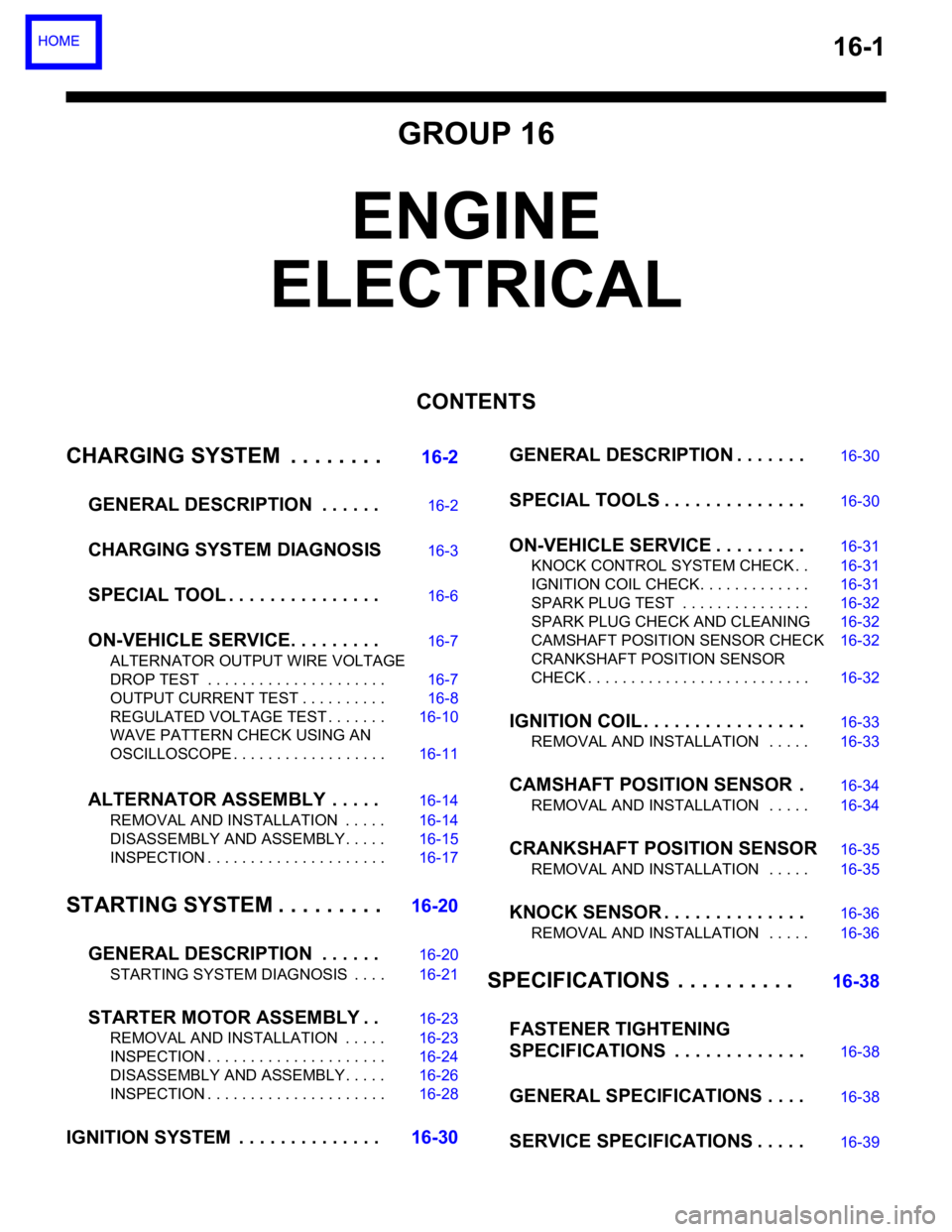
16-1
GROUP 16
ENGINE
ELECTRICAL
CONTENTS
CHARGING SYSTEM . . . . . . . .
16-2
GENERAL DESCRIPTION . . . . . .
16-2
CHARGING SYSTEM DIAGNOSIS16-3
SPECIAL TOOL . . . . . . . . . . . . . . .16-6
ON-VEHICLE SERVICE. . . . . . . . .16-7
ALTERNATOR OUTPUT WIRE VOLTAGE
DROP TEST . . . . . . . . . . . . . . . . . . . . . 16-7
OUTPUT CURRENT TEST . . . . . . . . . . 16-8
REGULATED VOLTAGE TEST . . . . . . . 16-10
WAVE PATTERN CHECK USING AN
OSCILLOSCOPE . . . . . . . . . . . . . . . . . . 16-11
ALTERNATOR ASSEMBLY . . . . .16-14
REMOVAL AND INSTALLATION . . . . . 16-14
DISASSEMBLY AND ASSEMBLY. . . . . 16-15
INSPECTION . . . . . . . . . . . . . . . . . . . . . 16-17
STARTING SYSTEM . . . . . . . . .16-20
GENERAL DESCRIPTION . . . . . .
16-20
STARTING SYSTEM DIAGNOSIS . . . . 16-21
STARTER MOTOR ASSEMBLY . .16-23
REMOVAL AND INSTALLATION . . . . . 16-23
INSPECTION . . . . . . . . . . . . . . . . . . . . . 16-24
DISASSEMBLY AND ASSEMBLY. . . . . 16-26
INSPECTION . . . . . . . . . . . . . . . . . . . . . 16-28
IGNITION SYSTEM . . . . . . . . . . . . . .16-30GENERAL DESCRIPTION . . . . . . .
16-30
SPECIAL TOOLS . . . . . . . . . . . . . .16-30
ON-VEHICLE SERVICE . . . . . . . . .16-31
KNOCK CONTROL SYSTEM CHECK . . 16-31
IGNITION COIL CHECK. . . . . . . . . . . . . 16-31
SPARK PLUG TEST . . . . . . . . . . . . . . . 16-32
SPARK PLUG CHECK AND CLEANING16-32
CAMSHAFT POSITION SENSOR CHECK16-32
CRANKSHAFT POSITION SENSOR
CHECK . . . . . . . . . . . . . . . . . . . . . . . . . . 16-32
IGNITION COIL . . . . . . . . . . . . . . . .16-33
REMOVAL AND INSTALLATION . . . . . 16-33
CAMSHAFT POSITION SENSOR .16-34
REMOVAL AND INSTALLATION . . . . . 16-34
CRANKSHAFT POSITION SENSOR16-35
REMOVAL AND INSTALLATION . . . . . 16-35
KNOCK SENSOR . . . . . . . . . . . . . .16-36
REMOVAL AND INSTALLATION . . . . . 16-36
SPECIFICATIONS . . . . . . . . . . 16-38
FASTENER TIGHTENING
SPECIFICATIONS . . . . . . . . . . . . .
16-38
GENERAL SPECIFICATIONS . . . .16-38
SERVICE SPECIFICATIONS . . . . .16-39
Page 993 of 1500
