Plug MITSUBISHI 380 2005 Workshop Manual
[x] Cancel search | Manufacturer: MITSUBISHI, Model Year: 2005, Model line: 380, Model: MITSUBISHI 380 2005Pages: 1500, PDF Size: 47.87 MB
Page 508 of 1500
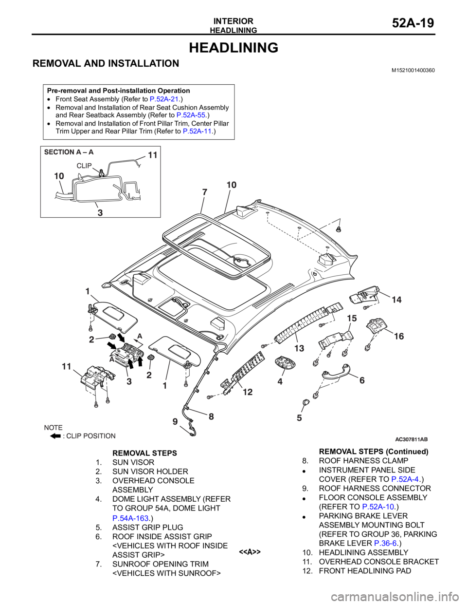
HEADLINING
INTERIOR52A-19
HEADLINING
REMOVAL AND INSTALLATIONM1521001400360
Pre-removal and Post-installation Operation
Front Seat Assembly (Refer to P.52A-21.)
Removal and Installation of Rear Seat Cushion Assembly
and Rear Seatback Assembly (Refer to P.52A-55.)
Removal and Installation of Front Pillar Trim, Center Pillar
Trim Upper and Rear Pillar Trim (Refer to P.52A-11.)
REMOVAL STEPS
1. SUN VISOR
2. SUN VISOR HOLDER
3. OVERHEAD CONSOLE
ASSEMBLY
4. DOME LIGHT ASSEMBLY (REFER
TO GROUP 54A, DOME LIGHT
P.54A-163.)
5. ASSIST GRIP PLUG
6. ROOF INSIDE ASSIST GRIP
7. SUNROOF OPENING TRIM
INSTRUMENT PANEL SIDE
COVER (REFER TO P.52A-4.)
9. ROOF HARNESS CONNECTOR
FLOOR CONSOLE ASSEMBLY
(REFER TO P.52A-10.)
PARKING BRAKE LEVER
ASSEMBLY MOUNTING BOLT
(REFER TO GROUP 36, PARKING
BRAKE LEVER P.36-6.)
<>10. HEADLINING ASSEMBLY
11. OVERHEAD CONSOLE BRACKET
12. FRONT HEADLINING PAD REMOVAL STEPS (Continued)
Page 853 of 1500
HEATER UNIT, HEATER CORE, BLOWER ASSEMBLY AND EVAPORATOR UNIT
HEATER, AIR CONDITIONING AND VENTILATION55-152
REMOVAL SERVICE POINTS
.
<> SUCTION PIPE AND LIQUID PIPE DISCON-
NECTION
As the compressor oil and receiver are highly moisture
absorbent, use a non-porous material to plug the hose and
nipples.
To prevent the entry of dust or other foreign bodies, plug the
dismantled hose and the nipples of the expansion valves.
.
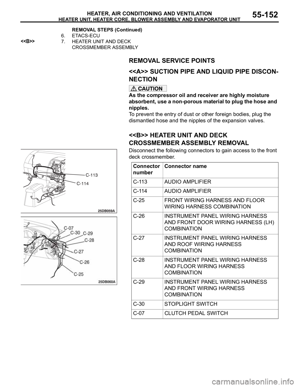
<> HEATER UNIT AND DECK
CROSSMEMBER ASSEMBLY REMOVAL
Disconnect the following connectors to gain access to the front
deck crossmember.
6. ETACS-ECU
<>7. HEATER UNIT AND DECK
CROSSMEMBER ASSEMBLY REMOVAL STEPS (Continued)
Connector
numberConnector name
C-113 AUDIO AMPLIFIER
C-114 AUDIO AMPLIFIER
C-25 FRONT WIRING HARNESS AND FLOOR
WIRING HARNESS COMBINATION
C-26 INSTRUMENT PANEL WIRING HARNESS
AND FRONT DOOR WIRING HARNESS (LH)
COMBINATION
C-27 INSTRUMENT PANEL WIRING HARNESS
AND ROOF WIRING HARNESS
COMBINATION
C-28 INSTRUMENT PANEL WIRING HARNESS
AND FLOOR WIRING HARNESS
COMBINATION
C-29 INSTRUMENT PANEL WIRING HARNESS
AND FRONT WIRING HARNESS
COMBINATION
C-30 STOPLIGHT SWITCH
C-07 CLUTCH PEDAL SWITCH
Page 866 of 1500

Page 869 of 1500
Page 872 of 1500
Page 942 of 1500
ON-VEHICLE SERVICE
ENGINE COOLING14-27
RADIATOR CAP PRESSURE CHECKM1141001300419
NOTE: Be sure that the cap is clean before testing. Rust or
other foreign material on the cap seal will cause an improper
reading.
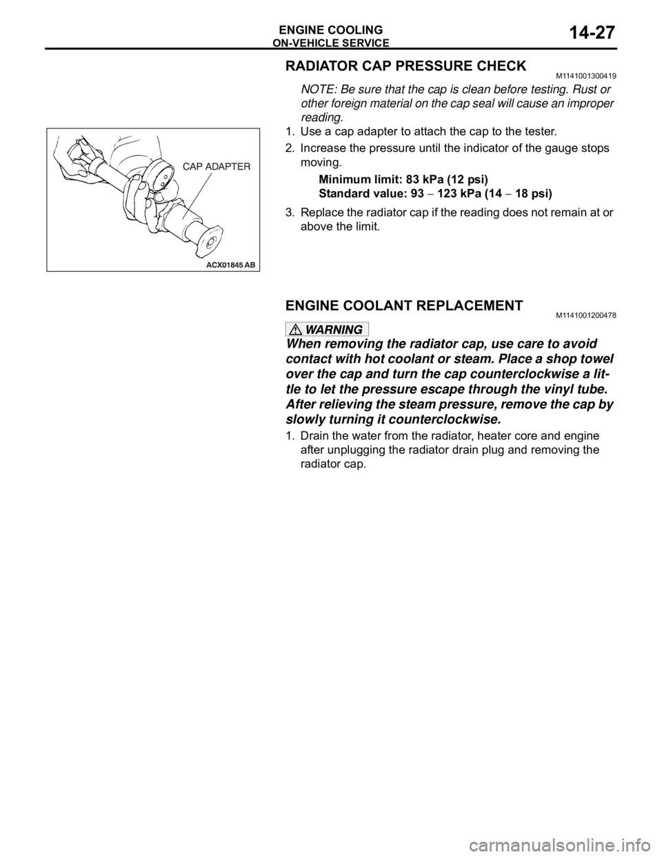
1. Use a cap adapter to attach the cap to the tester.
2. Increase the pressure until the indicator of the gauge stops
moving.
Minimum limit: 83 kPa (12 psi)
Standard value: 93
123 kPa (14 18 psi)
3. Replace the radiator cap if the reading does not remain at or
above the limit.
ENGINE COOLANT REPLACEMENTM1141001200478
When removing the radiator cap, use care to avoid
contact with hot coolant or steam. Place a shop towel
over the cap and turn the cap counterclockwise a lit-
tle to let the pressure escape through the vinyl tube.
After relieving the steam pressure, remove the cap by
slowly turning it counterclockwise.
1. Drain the water from the radiator, heater core and engine
after unplugging the radiator drain plug and removing the
radiator cap.
Page 943 of 1500
ON-VEHICLE SERVICE
ENGINE COOLING14-28
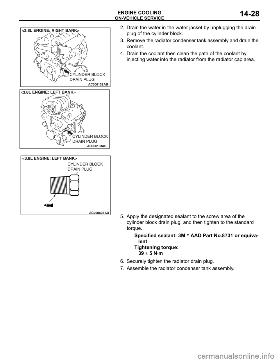
2. Drain the water in the water jacket by unplugging the drain
plug of the cylinder block.
3. Remove the radiator condenser tank assembly and drain the
coolant.
4. Drain the coolant then clean the path of the coolant by
injecting water into the radiator from the radiator cap area.
5. Apply the designated sealant to the screw area of the
cylinder block drain plug, and then tighten to the standard
torque.
Specified sealant: 3M
AAD Part No.8731 or equiva-
lent
Tightening torque:
39
5 Nm
6. Securely tighten the radiator drain plug.
7. Assemble the radiator condenser tank assembly.
Page 949 of 1500
Page 957 of 1500

SPECIFICATIONS
ENGINE COOLING14-42
SPECIFICATIONS
FASTENER TIGHTENING SPECIFICATIONSM1141005000346
ITEM SPECIFICATION
Cylinder block drain plug 39
5 Nm (29 3 ft-lb)
Radiator
Front end structure bar bolt M8
10 11 2 Nm (98 17 in-lb)
M8
20 22 4 Nm (16 3 ft-lb)
Thermostat
Control harness bolt 5.0
1.0 Nm (44 9 in-lb)
Grounding bolt M6 9.0
2.0 Nm (80 17 in-lb)
M8 22
4 Nm (16 3 ft-lb)
Water inlet fitting bolt 19
1 Nm (14 1 ft-lb)
Water hose and water pipe
Engine coolant temperature sensor 29
10 Nm
Thermostat housing bolt 19
1 Nm (14 1 ft-lb)
Water pump inlet pipe 11
1 Nm (98 8 ft-lb)
Water pump
Water pump bolt M8 42
8 Nm (31 6 ft-lb)
M10 24
3 Nm (18 2 ft-lb)
Water pump bracket bolt 24
3 Nm (18 2 ft-lb)
Page 958 of 1500

SPECIFICATIONS
ENGINE COOLING14-43
SERVICE SPECIFICATIONM1141000300449
CAPACITIESM1141005100138
SEALANTSM1141000500368
ITEM STANDARD VALUE LIMIT
Fan Controller V A/C OFF 1 or less -
A/C ON Repeat
8.2
2.6
System voltage
2.6-
High-pressure valve opening pressure of radiator cap kPa (psi) 93
123 (14 18) Minimum 83 (12)
Thermostat Valve opening temperature
of thermostat
C (F)3.8L Engine 88
1.5 (190 3)
-
Full-opening temperature
of thermostat
C (F)3.8L Engine 100 (212)
-
Valve lift mm (in) 3.8L Engine 9.0 (0.35) or more
-
ITEM
QUANTITY dm3 (qt)
Long life antifreeze coolant or an equivalent 3.8L Engine 8.7 (9.2)
ITEM SPECIFIED SEALANT
Cylinder block drain plug 3M
AAD Part No.8731 or equivalent
Engine coolant temperature sensor