Plug MITSUBISHI 380 2005 Owner's Manual
[x] Cancel search | Manufacturer: MITSUBISHI, Model Year: 2005, Model line: 380, Model: MITSUBISHI 380 2005Pages: 1500, PDF Size: 47.87 MB
Page 1265 of 1500
MAINTENANCE SERVICE
GENERAL00-44
8. EXHAUST SYSTEM (CONNECTIONS PORTION
OF MUFFLER, MUFFLER PIPES AND
CONVERTER HEAT SHIELDS) (CHECK AND
SERVICE AS REQUIRED)
M1001005800299
1. Check for holes and exhaust gas leaks due to damage,
corrosion, etc.
2. Check the joints and connections for looseness and exhaust
gas leaks.
3. Check the rubber hangers and brackets for damage.
9. ENGINE OIL (CHANGE)M1001002600360
Use the specified oil. (Refer to P.00-35.)
Use care as oil could be hot.
1. After warming up the engine, remove the oil filler cap.
2. Remove the drain plug to allow the engine oil to drain.
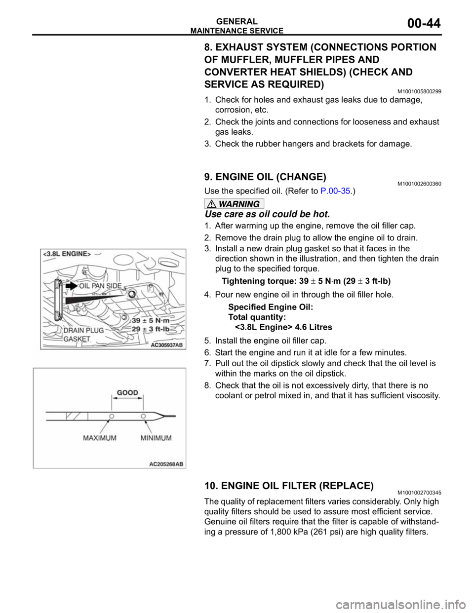
3. Install a new drain plug gasket so that it faces in the
direction shown in the illustration, and then tighten the drain
plug to the specified torque.
Tightening torque: 39
5 Nm (29 3 ft-lb)
4. Pour new engine oil in through the oil filler hole.
Specified Engine Oil:
To ta l q u a n t i t y :
<3.8L Engine> 4.6 Litres
5. Install the engine oil filler cap.
6. Start the engine and run it at idle for a few minutes.
7. Pull out the oil dipstick slowly and check that the oil level is
within the marks on the oil dipstick.
8. Check that the oil is not excessively dirty, that there is no
coolant or petrol mixed in, and that it has sufficient viscosity.
10. ENGINE OIL FILTER (REPLACE)M1001002700345
The quality of replacement filters varies considerably. Only high
quality filters should be used to assure most efficient service.
Genuine oil filters require that the filter is capable of withstand-
ing a pressure of 1,800 kPa (261 psi) are high quality filters.
.
Page 1266 of 1500
MAINTENANCE SERVICE
GENERAL00-45
Engine Oil Filter Selection
This vehicle is equipped with a full-flow, throw-away oil filter.
The same type of filter is recommended as a replacement filter
for this vehicle. It is possible, particularly in cold weather, that
this vehicle may develop high oil pressure for a short duration.
Make sure that any replacement filter used on this vehicle is a
high-quality filter. The filter must withstand a pressure of 1,800
kPa (261 psi) [manufacturer's specifications] to avoid filter and
ultimately engine damage. The Genuine Mitsubishi high-quality
filter and is strongly recommended for use on this vehicle.
Any replacement oil filter should be installed in accordance with
the oil filter manufacturer's installation instructions.
.
Oil Filter Replacement
Use care as oil could be hot.
1. Drain the engine oil by removing the oil drain plug.
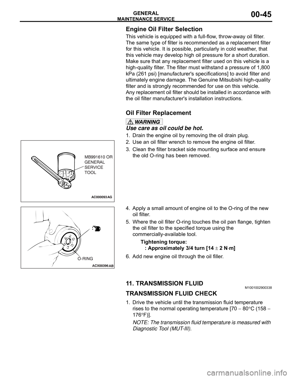
2. Use an oil filter wrench to remove the engine oil filter.
3. Clean the filter bracket side mounting surface and ensure
the old O-ring has been removed.
4. Apply a small amount of engine oil to the O-ring of the new
oil filter.
5. Where the oil filter O-ring touches the oil pan flange, tighten
the oil filter to the specified torque using the
commercially-available tool.
Tightening torque:
: Approximately 3/4 turn [14
2 Nm]
6. Add new engine oil through the oil filler.
11. TRANSMISSION FLUIDM1001002900338
TRANSMISSION FLUID CHECK
1. Drive the vehicle until the transmission fluid temperature
rises to the normal operating temperature [70
80C (158
176
F)].
NOTE: The transmission fluid temperature is measured with
Diagnostic Tool (MUT-III).
Page 1268 of 1500
MAINTENANCE SERVICE
GENERAL00-47
6. Securely insert the dipstick.
NOTE: The transmission fluid should always be replaced
under the following conditions:
.
When troubleshooting the transaxle.
When overhauling the transaxle.
When the transmission fluid is noticeably dirty or burnt
(driving under severe conditions).
TRANSMISSION FLUID CHANGE
Refer to GROUP 23A, Automatic Transmission - On-vehicle
Service P.23A-296.
12. ENGINE COOLANT (CHANGE)M1001003100357
Check the cooling system parts such as the radiator, heater
and oil cooler hoses, thermostat and their connections for leak-
age and damage.
.
CHANGING COOLANT
1. Set the temperature control knob to the "HOT" position.
2. Run the engine until the engine coolant warms, and then
stop the engine.
When removing the radiator cap, use care to avoid
contact with hot coolant or steam. Place a shop towel
over the cap and turn the cap counterclockwise a lit-
tle to let the pressure escape through the vinyl tube.
After relieving the steam pressure, remove the cap by
slowly turning it counterclockwise.
3. Drain the water from the radiator, heater core and engine
after unplugging the radiator drain plug and removing the
radiator cap.
Page 1269 of 1500
MAINTENANCE SERVICE
GENERAL00-48
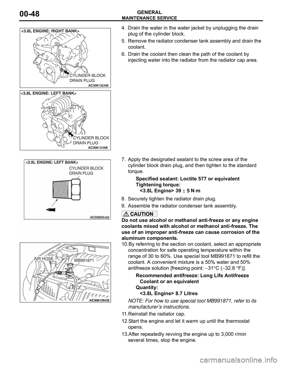
4. Drain the water in the water jacket by unplugging the drain
plug of the cylinder block.
5. Remove the radiator condenser tank assembly and drain the
coolant.
6. Drain the coolant then clean the path of the coolant by
injecting water into the radiator from the radiator cap area.
7. Apply the designated sealant to the screw area of the
cylinder block drain plug, and then tighten to the standard
torque.
Specified sealant: Loctite 577 or equivalent
Tightening torque:
<3.8L Engine> 39
5 Nm
8. Securely tighten the radiator drain plug.
9. Assemble the radiator condenser tank assembly.
Do not use alcohol or methanol anti-freeze or any engine
coolants mixed with alcohol or methanol anti-freeze. The
use of an improper anti-freeze can cause corrosion of the
aluminum components.
10.By referring to the section on coolant, select an appropriate
concentration for safe operating temperature within the
range of 30 to 60%. Use special tool MB991871 to refill the
coolant. A convenient mixture is a 50% water and 50%
antifreeze solution [freezing point:
31C (32.8 F)].
Recommended antifreeze: Long Life Antifreeze
Coolant or an equivalent
Quantity:
<3.8L Engine> 8.7 Litres
NOTE: For how to use special tool MB991871, refer to its
manufacturer’s instructions.
11.Reinstall the radiator cap.
12.Start the engine and let it warm up until the thermostat
opens.
13.After repeatedly revving the engine up to 3,000 r/min
several times, stop the engine.
Page 1411 of 1500
EMISSION CONTROL
ENGINE AND EMISSION CONTROL17-80
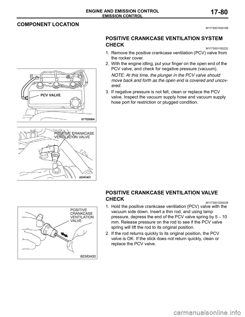
COMPONENT LOCATIONM1173007400189
POSITIVE CRANKCASE VENTILATION SYSTEM
CHECK
M1173001100232
1. Remove the positive crankcase ventilation (PCV) valve from
the rocker cover.
2. With the engine idling, put your finger on the open end of the
PCV valve, and check for negative pressure (vacuum).
NOTE: At this time, the plunger in the PCV valve should
move back and forth as the open end is covered and uncov-
ered.
3. If negative pressure is not felt, clean or replace the PCV
valve. Inspect the vacuum supply hose and vacuum supply
hose port for restriction or plugged condition.
POSITIVE CRANKCASE VENTILATION VALVE
CHECK
M1173001200228
1. Hold the positive crankcase ventilation (PCV) valve with the
vacuum side down. Insert a thin rod, and using lamp
pressure, depress the end of the PCV valve spring by 5
10
mm. Release pressure on the rod to see if the PCV valve
spring will lift the rod to its original position.
2. If the rod returns quickly to its original position, the PCV
valve is OK. If the stick does not return quickly, clean or
replace the PCV valve.
Page 1453 of 1500
REAR AXLE HUB ASSEMBLY
REAR AXLE27-6
REAR AXLE HUB ASSEMBLY
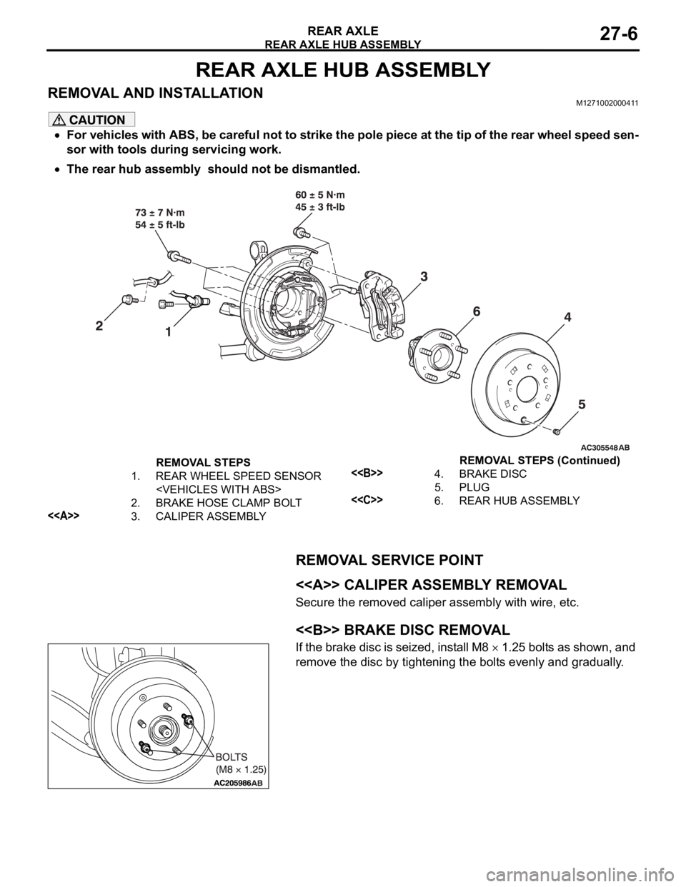
REMOVAL AND INSTALLATIONM1271002000411
For vehicles with ABS, be careful not to strike the pole piece at the tip of the rear wheel speed sen-
sor with tools during servicing work.
The rear hub assembly should not be dismantled.
REMOVAL SERVICE POINT
.
<> CALIPER ASSEMBLY REMOVAL
Secure the removed caliper assembly with wire, etc.
.
<> BRAKE DISC REMOVAL
If the brake disc is seized, install M8 1.25 bolts as shown, and
remove the disc by tightening the bolts evenly and gradually.
.
REMOVAL STEPS
1. REAR WHEEL SPEED SENSOR
2. BRAKE HOSE CLAMP BOLT
<>3. CALIPER ASSEMBLY
<>4. BRAKE DISC
5. PLUG
<
Page 1486 of 1500
![MITSUBISHI 380 2005 Owners Manual AUTOMATIC TRANSMISSION DIAGNOSIS
AUTOMATIC TRANSMISSION23A-27
3. Connect the special tools (3.0 MPa (427 psi) oil pressure
gauge [MD998330] and adapters [MD998332, MD998900])
to each pressure discha MITSUBISHI 380 2005 Owners Manual AUTOMATIC TRANSMISSION DIAGNOSIS
AUTOMATIC TRANSMISSION23A-27
3. Connect the special tools (3.0 MPa (427 psi) oil pressure
gauge [MD998330] and adapters [MD998332, MD998900])
to each pressure discha](/img/19/57086/w960_57086-1485.png)
AUTOMATIC TRANSMISSION DIAGNOSIS
AUTOMATIC TRANSMISSION23A-27
3. Connect the special tools (3.0 MPa (427 psi) oil pressure
gauge [MD998330] and adapters [MD998332, MD998900])
to each pressure discharge port.
NOTE: .
2ND: Second brake pressure port
UD: Underdrive clutch pressure port
LR: Low-reverse brake pressure port
DR: Torque converter release pressure port
DA: Torque converter apply pressure port
RV: Reverse clutch pressure port
OD: Overdrive clutch pressure port
DIR: Direct clutch pressure port
RED: Reduction clutch pressure port
4. Restart the engine.
5. Check that there are no leaks around the special tool port
adapters.
6. Measure the hydraulic pressure at each port under the
conditions given in the standard hydraulic pressure table,
and check that the measured values are within the standard
value ranges.
7. If the pressure is not within the standard value, stop the
engine and refer to the hydraulic pressure test diagnosis
table.
8. Remove the O-ring from the port plug and replace it.
9. Remove the special tool, and install the plugs to the
hydraulic pressure ports.
10.Start the engine and check that there are no leaks around
the plugs.