headlights MITSUBISHI 380 2005 Workshop Manual
[x] Cancel search | Manufacturer: MITSUBISHI, Model Year: 2005, Model line: 380, Model: MITSUBISHI 380 2005Pages: 1500, PDF Size: 47.87 MB
Page 18 of 1500

SWS DIAGNOSIS
SIMPLIFIED WIRING SYSTEM (SWS)54B-18
Front-ECU, P/W, S/R
NOTE: For item No.70, the diagnostic tool
MB991958 (MUT-III Sub Assembly) also displays
"NG" under "ECU COMM Check" when it displays
"NO ACK" under the front-ECU check.NOTE: For item No.72, the diagnostic tool
MB991958 (MUT-III Sub Assembly) also displays
"NG" under "ECU COMM Check" when it displays
"NO ACK" under the sunroof-ECU check.
The table below shows the service data and their
normal condition, which are displayed during the
"Function Diag." The column "Normal condition"
shows values that are shown when each operation is
made.
.
CHECK
ITEMITEM NO. DISPLAY ON
DIAGNOSTIC
TOOLCHECK CONDITION NORMAL
CONDITION
Response by
the
front-ECU70 FRONT ECU
ACKLighting switch: Other than OFF (excluding
when high-beam is on) or the wiper switch
is at position other than OFF (ignition
switch: ACC or ON)NORMAL ACK
Ignition switch: Other than ON
Lighting switch: OFF
Wiper switch: OFFSLEEP ACK
Lighting switch: HEAD
Headlights: at high beamHI-BEAM ACK
Other than the condition above NO ACK
Response by
the
sunroof-ECU72 S/R ECU ACK
1. Door switch: OFF
2. Ignition switch: ON
OFF
3. While sunroof is offNORMAL ACK
SLEEP ACK (after
approximately 30
seconds)
1. Ignition switch: ON or START
2. One of the sunroof switches is onINPUT CHECK to
NORMAL ACK
Other than the above conditions NO ACK
Page 59 of 1500

SYMPTOM CHART
SIMPLIFIED WIRING SYSTEM (SWS)54B-59
Headlamp and
taillampGeneral description concerning the headlamp and
taillampP.54B-257
The taillights do not illuminate normally. H-1
P.54B-260
The headlamps (low-beam) do not illuminate
normally.H-2
P.54B-264
The headlamps (high-beam) do not illuminate
normally.H-3
P.54B-268
When the passing switch is turned "ON," the
headlamps (low-beam or high-beam) do not
illuminate.H-4
P.54B-271
Headlights do not illuminate when the lighting
switch is at "TAIL," and "PASSING" position, but
illuminate at low-beam when the switch is at
"HEAD" position. At this position, the headlamps
cannot be changed to high beam by operating the
dimmer switch.H-5
P.54B-273
The taillamps, the position lamps, front parking
lamps or the license plate lamp do not illuminate.H-6
P.54B-275
One of the headlamps does not illuminate. H-7
P.54B-290
The high-beam indicator lamp does not illuminate. H-8
P.54B-301
Headlamp automatic shutoff function does not
work normally.H-9
P.54B-305
Headlamp dimmer switch automatic resetting
function does not work normally.H-10
P.54B-308
Flasher timer General description concerning the flasher timer
P.54B-309
Turn-signal lamps do not flash when the
turn-signal lamp switch is turned on.I-1
P.54B-310
Hazard warning lamps do not flash when the
hazard warning lamp switch is turned on.I-2
P.54B-314
One of the turn-signal lamps does not illuminate. I-3
P.54B-316
The turn-signal lamp indicator does not illuminate
normally.I-4
P.54B-335
Fog lamp General description concerning the fog lamps
P.54B-339
Fog lamps do not illuminate when the fog lamp
switch is turned on.J-1
P.54B-340
Fog lamps do not go out when the headlamps
(low-beam) are turned off while the fog lamps are
on.J-2
P.54B-345
One of the fog lamps does not illuminate. J-3
P.54B-345
The fog lamp indicator does not illuminate
normally.J-4
P.54B-350 SYSTEM SYMPTOM INSPECTION
PROCEDUREREFERENCE
PA G E
Page 484 of 1500

CHECK AT ECU TERMINAL
SIMPLIFIED WIRING SYSTEM (SWS)54B-484
FRONT-ECU
NOTE: Terminal voltages cannot be measured as the
front-ECU is installed directly on the relay box.
Therefore, this information is only for reference.
TERMINAL
NO.INSPECTION ITEM INSPECTION CONDITION NORMAL VALUE
1 Output to fog lamp relay When the fog lamps are on Battery positive voltage
2 Output to headlamp (high-beam) When headlights (high-beam)
are onBattery positive voltage
3, 4 Battery power supply (for
headlamp)Always Battery positive voltage
5 Battery power supply (for
taillamp)Always Battery positive voltage
6 Output to headlamp (low-beam) When headlights (low-beam) are
onBattery positive voltage
7 Battery power supply (for ECU) Always Battery positive voltage
8 Output to taillamps When taillamps are on Battery positive voltage
9
11
21 Output to windshield washer When windshield washer is on Battery positive voltage
22 SWS communication line Always 0
12 V (pulse signal)
23 Input of automatic stop signal to
windshield wiperWhen windshield wiper is on Battery positive voltage
24 Power supply to ignition switch
(ACC)Ignition switch: "ACC" Battery positive voltage
25 Input of backup signal from
headlamp switchHeadlamp switch: ON0 V
26 Input of backup signal to
windshield wiperWindshield low-speed wiper
switch or windshield high-speed
wiper switch: ON0 V
27 Output to windshield wiper
(low-speed)When windshield wiper is on (at
low speed)Battery positive voltage
28 Output to windshield wiper
(high-speed)When windshield wiper is on (at
high speed)Battery positive voltage
30 Power supply to ignition switch
(IG2)Ignition switch: "ON" Battery positive voltage
31 Ground Always 0 V
Page 985 of 1500

CHARGING SYSTEM
ENGINE ELECTRICAL16-8
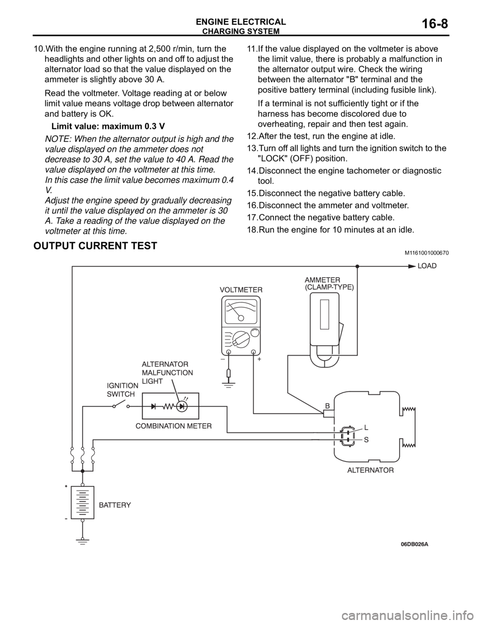
10.With the engine running at 2,500 r/min, turn the
headlights and other lights on and off to adjust the
alternator load so that the value displayed on the
ammeter is slightly above 30 A.
Read the voltmeter. Voltage reading at or below
limit value means voltage drop between alternator
and battery is OK.
Limit value: maximum 0.3 V
NOTE: When the alternator output is high and the
value displayed on the ammeter does not
decrease to 30 A, set the value to 40 A. Read the
value displayed on the voltmeter at this time.
In this case the limit value becomes maximum 0.4
V.
Adjust the engine speed by gradually decreasing
it until the value displayed on the ammeter is 30
A. Take a reading of the value displayed on the
voltmeter at this time.11.If the value displayed on the voltmeter is above
the limit value, there is probably a malfunction in
the alternator output wire. Check the wiring
between the alternator "B" terminal and the
positive battery terminal (including fusible link).
If a terminal is not sufficiently tight or if the
harness has become discolored due to
overheating, repair and then test again.
12.After the test, run the engine at idle.
13.Turn off all lights and turn the ignition switch to the
"LOCK" (OFF) position.
14.Disconnect the engine tachometer or diagnostic
tool.
15.Disconnect the negative battery cable.
16.Disconnect the ammeter and voltmeter.
17.Connect the negative battery cable.
18.Run the engine for 10 minutes at an idle.
OUTPUT CURRENT TESTM1161001000670
Page 986 of 1500

CHARGING SYSTEM
ENGINE ELECTRICAL16-9
Required Special Tool:
: Diagnostic Tool (MUT-III)
MB991824: V.C.I.
MB991827: MUT-III USB Cable
MB991910: MUT-III Main Harness A
This test determines whether the alternator outputs
normal current. For best results, use a charging sys-
tem tester. If not available, follow the steps below.
Battery posts, terminals and related acces-
sories contain lead and lead compounds.
WASH HANDS AFTER HANDLING.
1. Before the test, always be sure to check the
following.
Alternator installation
Battery (Refer to GROUP 54A, Chassis Electrical
Battery On-vehicle Service Battery Check
P.54A-5.)
NOTE: The battery to be used should be slightly
discharged. The load in a fully-charged battery
will be insufficient and the test may not be able to
be carried out correctly.
Alternator drive belt tension (Refer to GROUP 00,
General
Maintenance Service Drive Belts
(For Alternator, Power Steering Pump and Air
Conditioning) (Check) P.00-39.)
Fusible link
Abnormal noise from the alternator while the
engine is running.
2. Turn the ignition switch to the "LOCK" (OFF)
position.
3. Disconnect the negative battery cable.
Never use clips to connect the wire. Loose
connections (for example, using clips) will
lead to a serious accident because of high
current.
4. Connect a clamp-type DC test ammeter with a
range of 0
120 A to the alternator "B" terminal
output wire.
5. Connect a voltmeter with a range of 0
20 V
between the alternator "B" terminal and ground.
(Connect the positive lead of the voltmeter to the
"B" terminal, and then connect the negative lead
of the voltmeter to ground.)
6. Connect the negative battery cable.
7. Connect an engine tachometer or diagnostic tool.
8. Leave the hood open.9. Check to be sure that the reading on the voltmeter
is equal to the battery positive voltage.
NOTE: If the voltage is 0 V, the cause is probably
an open circuit in the wire or fusible link between
the alternator "B" terminal and the battery positive
terminal or malfunctioning voltmeter.
10.After turning on the headlights, start the engine.
NOTE: Because the current from the battery will
soon drop after the engine is started, step 11
should be carried out as quickly as possible in
order to obtain the maximum current output value.
11.Immediately after setting the headlights to high
beam and turning the heater blower switch to the
highest position, increase the engine speed to
2,500 r/min and read the maximum current output
value displayed on the ammeter.
Limit value: 70 % of nominal current output
NOTE: For the nominal current output, refer to the
Alternator Specifications.
NOTE: The current output value will depend on
the electrical load and the temperature of the
alternator body.
NOTE: If the electrical load is small while testing,
the specified level of current may not be output
even though the alternator is normal. In such
cases, increase the electrical load by leaving the
headlights turned on for some time to discharge
the battery or by using the lighting system in
another vehicle, and then test again.
NOTE: The specified level of current also may not
be output if the temperature of the alternator body
or the ambient temperature is too high. In such
cases, cool the alternator and then test again.
12.The reading on the ammeter should be above the
limit value. If the reading is below the limit value
and the alternator output wire is normal, remove
the alternator from the engine and check the
alternator.
13.Run the engine at idle speed after the test.
14.Turn the ignition switch to the "LOCK" (OFF)
position.
15.Disconnect the engine tachometer or diagnostic
tool.
16.Disconnect the negative battery cable.
17.Disconnect the ammeter and voltmeter .
18.Connect the negative battery cable.
19.Run the engine for 10 minutes at an idle.
Page 989 of 1500

CHARGING SYSTEM
ENGINE ELECTRICAL16-12
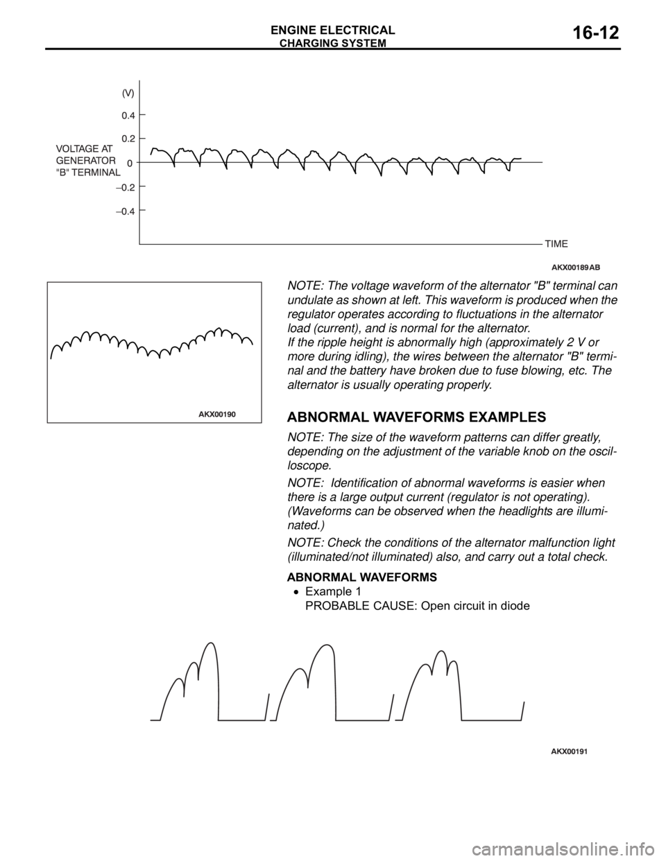
NOTE: The voltage waveform of the alternator "B" terminal can
undulate as shown at left. This waveform is produced when the
regulator operates according to fluctuations in the alternator
load (current), and is normal for the alternator.
If the ripple height is abnormally high (approximately 2 V or
more during idling), the wires between the alternator "B" termi-
nal and the battery have broken due to fuse blowing, etc. The
alternator is usually operating properly.
.
ABNORMAL WAVEFORMS EXAMPLES
NOTE: The size of the waveform patterns can differ greatly,
depending on the adjustment of the variable knob on the oscil-
loscope.
NOTE: Identification of abnormal waveforms is easier when
there is a large output current (regulator is not operating).
(Waveforms can be observed when the headlights are illumi-
nated.)
NOTE: Check the conditions of the alternator malfunction light
(illuminated/not illuminated) also, and carry out a total check.
ABNORMAL WAVEFORMS
Example 1
PROBABLE CAUSE: Open circuit in diode