check transmission fluid MITSUBISHI 380 2005 Workshop Manual
[x] Cancel search | Manufacturer: MITSUBISHI, Model Year: 2005, Model line: 380, Model: MITSUBISHI 380 2005Pages: 1500, PDF Size: 47.87 MB
Page 1223 of 1500
GENERAL00-2
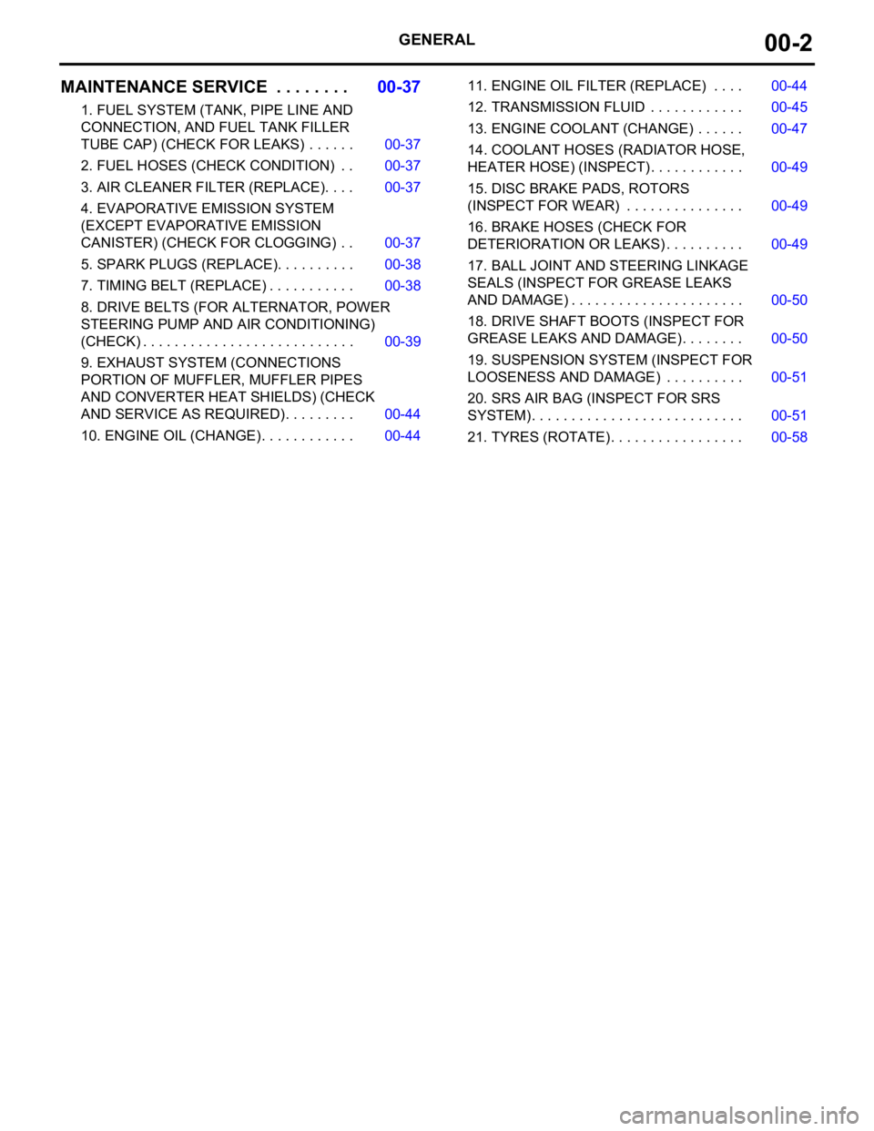
MAINTENANCE SERVICE . . . . . . . .00-37
1. FUEL SYSTEM (TANK, PIPE LINE AND
CONNECTION, AND FUEL TANK FILLER
TUBE CAP) (CHECK FOR LEAKS) . . . . . . 00-37
2. FUEL HOSES (CHECK CONDITION) . . 00-37
3. AIR CLEANER FILTER (REPLACE). . . . 00-37
4. EVAPORATIVE EMISSION SYSTEM
(EXCEPT EVAPORATIVE EMISSION
CANISTER) (CHECK FOR CLOGGING) . . 00-37
5. SPARK PLUGS (REPLACE). . . . . . . . . . 00-38
7. TIMING BELT (REPLACE) . . . . . . . . . . . 00-38
8. DRIVE BELTS (FOR ALTERNATOR, POWER
STEERING PUMP AND AIR CONDITIONING)
(CHECK) . . . . . . . . . . . . . . . . . . . . . . . . . . . 00-39
9. EXHAUST SYSTEM (CONNECTIONS
PORTION OF MUFFLER, MUFFLER PIPES
AND CONVERTER HEAT SHIELDS) (CHECK
AND SERVICE AS REQUIRED) . . . . . . . . . 00-44
10. ENGINE OIL (CHANGE) . . . . . . . . . . . . 00-4411. ENGINE OIL FILTER (REPLACE) . . . . 00-44
12. TRANSMISSION FLUID . . . . . . . . . . . . 00-45
13. ENGINE COOLANT (CHANGE) . . . . . . 00-47
14. COOLANT HOSES (RADIATOR HOSE,
HEATER HOSE) (INSPECT). . . . . . . . . . . . 00-49
15. DISC BRAKE PADS, ROTORS
(INSPECT FOR WEAR) . . . . . . . . . . . . . . . 00-49
16. BRAKE HOSES (CHECK FOR
DETERIORATION OR LEAKS) . . . . . . . . . . 00-49
17. BALL JOINT AND STEERING LINKAGE
SEALS (INSPECT FOR GREASE LEAKS
AND DAMAGE) . . . . . . . . . . . . . . . . . . . . . . 00-50
18. DRIVE SHAFT BOOTS (INSPECT FOR
GREASE LEAKS AND DAMAGE) . . . . . . . . 00-50
19. SUSPENSION SYSTEM (INSPECT FOR
LOOSENESS AND DAMAGE) . . . . . . . . . . 00-51
20. SRS AIR BAG (INSPECT FOR SRS
SYSTEM). . . . . . . . . . . . . . . . . . . . . . . . . . . 00-51
21. TYRES (ROTATE). . . . . . . . . . . . . . . . . 00-58
Page 1266 of 1500
MAINTENANCE SERVICE
GENERAL00-45
Engine Oil Filter Selection
This vehicle is equipped with a full-flow, throw-away oil filter.
The same type of filter is recommended as a replacement filter
for this vehicle. It is possible, particularly in cold weather, that
this vehicle may develop high oil pressure for a short duration.
Make sure that any replacement filter used on this vehicle is a
high-quality filter. The filter must withstand a pressure of 1,800
kPa (261 psi) [manufacturer's specifications] to avoid filter and
ultimately engine damage. The Genuine Mitsubishi high-quality
filter and is strongly recommended for use on this vehicle.
Any replacement oil filter should be installed in accordance with
the oil filter manufacturer's installation instructions.
.
Oil Filter Replacement
Use care as oil could be hot.
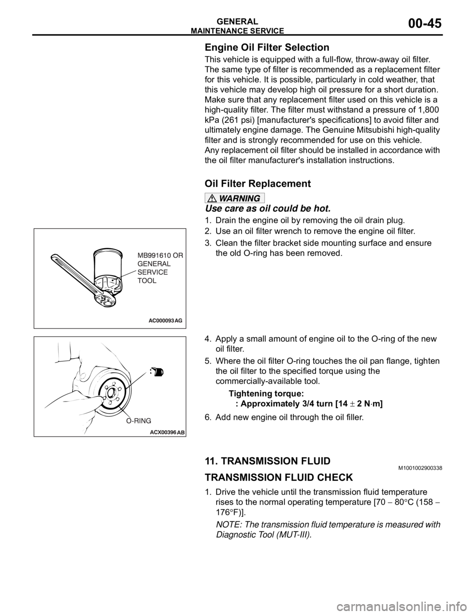
1. Drain the engine oil by removing the oil drain plug.
2. Use an oil filter wrench to remove the engine oil filter.
3. Clean the filter bracket side mounting surface and ensure
the old O-ring has been removed.
4. Apply a small amount of engine oil to the O-ring of the new
oil filter.
5. Where the oil filter O-ring touches the oil pan flange, tighten
the oil filter to the specified torque using the
commercially-available tool.
Tightening torque:
: Approximately 3/4 turn [14
2 Nm]
6. Add new engine oil through the oil filler.
11. TRANSMISSION FLUIDM1001002900338
TRANSMISSION FLUID CHECK
1. Drive the vehicle until the transmission fluid temperature
rises to the normal operating temperature [70
80C (158
176
F)].
NOTE: The transmission fluid temperature is measured with
Diagnostic Tool (MUT-III).
Page 1267 of 1500
![MITSUBISHI 380 2005 Workshop Manual MAINTENANCE SERVICE
GENERAL00-46
NOTE: If it takes some amount of time until the transmission
fluid reaches its normal operating temperature [70
80C
(158
176F)], check the transmission fluid lev MITSUBISHI 380 2005 Workshop Manual MAINTENANCE SERVICE
GENERAL00-46
NOTE: If it takes some amount of time until the transmission
fluid reaches its normal operating temperature [70
80C
(158
176F)], check the transmission fluid lev](/img/19/57086/w960_57086-1266.png)
MAINTENANCE SERVICE
GENERAL00-46
NOTE: If it takes some amount of time until the transmission
fluid reaches its normal operating temperature [70
80C
(158
176F)], check the transmission fluid level by refer-
ring to the left diagram.
2. Park the vehicle on a level surface.
3. Move the selector lever through all positions to fill the torque
converter and the hydraulic circuits with fluid, and then move
the selector lever to the "N" position.
4. After wiping off any dirt around the dipstick, remove the
dipstick and check the condition of the transmission fluid.
NOTE: If the transmission fluid smells as if it is burnt, it
means that the transmission fluid has been contaminated by
fine particles from the bushings and friction materials. Tran-
saxle overhaul and cooler line flushing may be necessary.
5. Check transmission fluid level is at the "HOT" mark on the
dipstick. If the transmission fluid level is less than this, add
DIAMOND ATF SP III until the level reaches the "HOT"
mark.
NOTE: If the transmission fluid level is too low, the oil pump
will draw in air along with the transmission fluid, which will
cause to form bubbles. If the transmission fluid level is too
high, rotating components inside the transaxle will churn the
fluid and air into a foamy liquid. Both conditions (level too
low or too high) will cause the hydraulic pressure to drop,
which will result in late shifting and slipping of the clutches
and brakes.
NOTE: In either case, air bubbles can interfere with normal
valve, clutch, and brake operation. Also, foaming can cause
transmission fluid to escape from the transaxle vent where it
may be mistaken for a leak.
Page 1268 of 1500
MAINTENANCE SERVICE
GENERAL00-47
6. Securely insert the dipstick.
NOTE: The transmission fluid should always be replaced
under the following conditions:
.
When troubleshooting the transaxle.
When overhauling the transaxle.
When the transmission fluid is noticeably dirty or burnt
(driving under severe conditions).
TRANSMISSION FLUID CHANGE
Refer to GROUP 23A, Automatic Transmission - On-vehicle
Service P.23A-296.
12. ENGINE COOLANT (CHANGE)M1001003100357
Check the cooling system parts such as the radiator, heater
and oil cooler hoses, thermostat and their connections for leak-
age and damage.
.
CHANGING COOLANT
1. Set the temperature control knob to the "HOT" position.
2. Run the engine until the engine coolant warms, and then
stop the engine.
When removing the radiator cap, use care to avoid
contact with hot coolant or steam. Place a shop towel
over the cap and turn the cap counterclockwise a lit-
tle to let the pressure escape through the vinyl tube.
After relieving the steam pressure, remove the cap by
slowly turning it counterclockwise.
3. Drain the water from the radiator, heater core and engine
after unplugging the radiator drain plug and removing the
radiator cap.
Page 1430 of 1500
DRIVE SHAFT ASSEMBLY
FRONT AXLE26-13
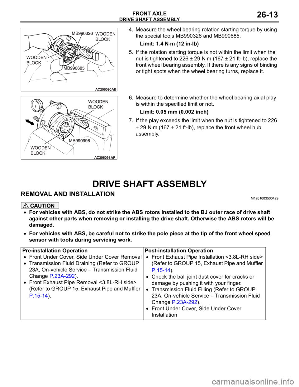
4. Measure the wheel bearing rotation starting torque by using
the special tools MB990326 and MB990685.
Limit: 1.4 N
m (12 in-lb)
5. If the rotation starting torque is not within the limit when the
nut is tightened to 226
29 Nm (167 21 ft-lb), replace the
front wheel bearing assembly. If there is any signs of binding
or tight spots when the wheel bearing turns, replace it.
6. Measure to determine whether the wheel bearing axial play
is within the specified limit or not.
Limit: 0.05 mm (0.002 inch)
7. If the play exceeds the limit when the nut is tightened to 226
29 Nm (167 21 ft-lb), replace the front wheel hub
assembly.
DRIVE SHAFT ASSEMBLY
REMOVAL AND INSTALLATIONM1261003500429
For vehicles with ABS, do not strike the ABS rotors installed to the BJ outer race of drive shaft
against other parts when removing or installing the drive shaft. Otherwise the ABS rotors will be
damaged.
For vehicles with ABS, be careful not to strike the pole piece at the tip of the front wheel speed
sensor with tools during servicing work.
Pre-installation Operation
Front Under Cover, Side Under Cover Removal
Transmission Fluid Draining (Refer to GROUP
23A, On-vehicle Service
Transmission Fluid
Change P.23A-292).
Front Exhaust Pipe Removal <3.8L-RH side>
(Refer to GROUP 15, Exhaust Pipe and Muffler
P.15-14).Post-installation Operation
Front Exhaust Pipe Installation <3.8L-RH side>
(Refer to GROUP 15, Exhaust Pipe and Muffler
P.15-14).
Check the ball joint dust cover for cracks or
damage by pushing it with your finger.
Transmission Fluid Filling (Refer to GROUP
23A, On-vehicle Service
Transmission Fluid
Change P.23A-292).
Front Under Cover, Side Under Cover
Installation
Page 1461 of 1500
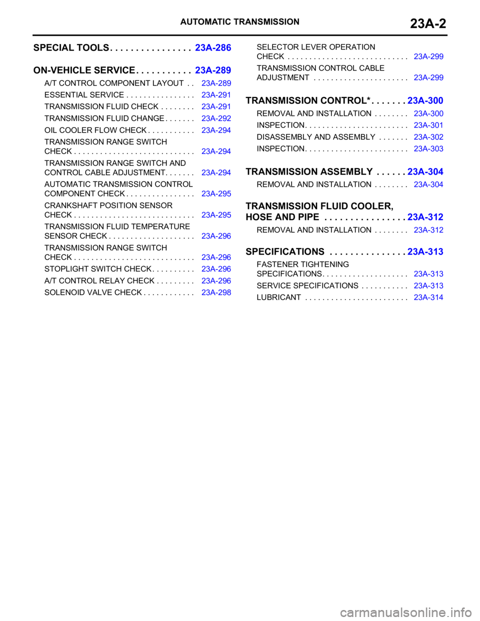
AUTOMATIC TRANSMISSION23A-2
SPECIAL TOOLS . . . . . . . . . . . . . . . .23A-286
ON-VEHICLE SERVICE. . . . . . . . . . .23A-289
A/T CONTROL COMPONENT LAYOUT . . 23A-289
ESSENTIAL SERVICE . . . . . . . . . . . . . . . . 23A-291
TRANSMISSION FLUID CHECK . . . . . . . . 23A-291
TRANSMISSION FLUID CHANGE . . . . . . . 23A-292
OIL COOLER FLOW CHECK . . . . . . . . . . . 23A-294
TRANSMISSION RANGE SWITCH
CHECK . . . . . . . . . . . . . . . . . . . . . . . . . . . . 23A-294
TRANSMISSION RANGE SWITCH AND
CONTROL CABLE ADJUSTMENT. . . . . . . 23A-294
AUTOMATIC TRANSMISSION CONTROL
COMPONENT CHECK . . . . . . . . . . . . . . . . 23A-295
CRANKSHAFT POSITION SENSOR
CHECK . . . . . . . . . . . . . . . . . . . . . . . . . . . . 23A-295
TRANSMISSION FLUID TEMPERATURE
SENSOR CHECK . . . . . . . . . . . . . . . . . . . . 23A-296
TRANSMISSION RANGE SWITCH
CHECK . . . . . . . . . . . . . . . . . . . . . . . . . . . . 23A-296
STOPLIGHT SWITCH CHECK . . . . . . . . . . 23A-296
A/T CONTROL RELAY CHECK . . . . . . . . . 23A-296
SOLENOID VALVE CHECK . . . . . . . . . . . . 23A-298SELECTOR LEVER OPERATION
CHECK . . . . . . . . . . . . . . . . . . . . . . . . . . . . 23A-299
TRANSMISSION CONTROL CABLE
ADJUSTMENT . . . . . . . . . . . . . . . . . . . . . . 23A-299
TRANSMISSION CONTROL* . . . . . . .23A-300
REMOVAL AND INSTALLATION . . . . . . . . 23A-300
INSPECTION. . . . . . . . . . . . . . . . . . . . . . . . 23A-301
DISASSEMBLY AND ASSEMBLY . . . . . . . 23A-302
INSPECTION. . . . . . . . . . . . . . . . . . . . . . . . 23A-303
TRANSMISSION ASSEMBLY . . . . . .23A-304
REMOVAL AND INSTALLATION . . . . . . . . 23A-304
TRANSMISSION FLUID COOLER,
HOSE AND PIPE . . . . . . . . . . . . . . . .23A-312
REMOVAL AND INSTALLATION . . . . . . . . 23A-312
SPECIFICATIONS . . . . . . . . . . . . . . .23A-313
FASTENER TIGHTENING
SPECIFICATIONS. . . . . . . . . . . . . . . . . . . . 23A-313
SERVICE SPECIFICATIONS . . . . . . . . . . . 23A-313
LUBRICANT . . . . . . . . . . . . . . . . . . . . . . . . 23A-314
Page 1472 of 1500
AUTOMATIC TRANSMISSION DIAGNOSIS
AUTOMATIC TRANSMISSION23A-13
A/T DIAGNOSTIC TROUBLESHOOTING STRATEGYM1231007600339
Use these steps to plan your diagnostic strategy. If
you follow them carefully, you will find most A/T mal-
functions.
1. Gather as much information as possible about the
complaint from the customer.
2. Verify that the condition described by the
customer exists.
3. Check the vehicle for any A/T Diagnostic Trouble
Codes (DTCs).
4. If you can not verify the condition and there are no
DTCs, the malfunction is intermittent. For
information on how to cope with intermittent
malfunctions, refer to GROUP 00, How to Use
Troubleshooting/Inspection Service Points
How
to Cope with Intermittent Malfunction P.00-14.
5. If you can verify the condition but there are no
DTCs, or the system can not communicate with
diagnostic tool, refer to the Symptom Chart
P.23A-35.6. If there is a DTC, record the number of the code,
then erase the code from memory using
diagnostic tool.
7. Reconfirm the symptom with a Road Test.
8. If a DTC is set again, go to the Inspection Chart
for Diagnostic Trouble Codes.
9. If a DTC is not set again, the malfunction is
intermittent. For information on how to cope with
intermittent malfunctions, refer to GROUP 00,
How to Use Troubleshooting/Inspection Service
Points
How to Cope with Intermittent
Malfunction P.00-14.
10.After repairs are completed, conduct a Road Test
duplicating the complaint conditions to confirm the
malfunction has been eliminated.
DIAGNOSTIC FUNCTIONM1231022500135
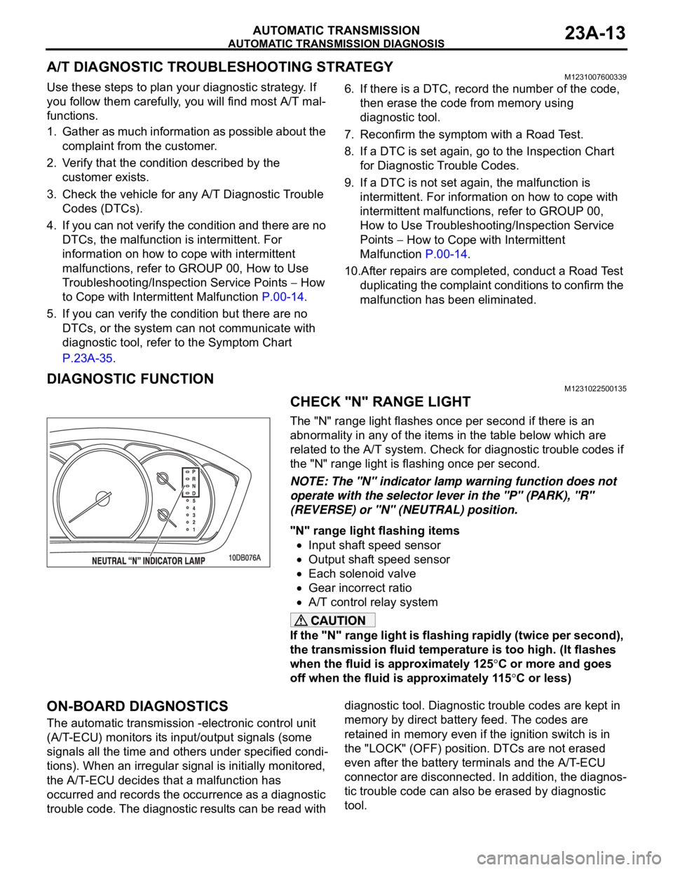
CHECK "N" RANGE LIGHT
The "N" range light flashes once per second if there is an
abnormality in any of the items in the table below which are
related to the A/T system. Check for diagnostic trouble codes if
the "N" range light is flashing once per second.
NOTE: The "N" indicator lamp warning function does not
operate with the selector lever in the "P" (PARK), "R"
(REVERSE) or "N" (NEUTRAL) position.
"N" range light flashing items
Input shaft speed sensor
Output shaft speed sensor
Each solenoid valve
Gear incorrect ratio
A/T control relay system
If the "N" range light is flashing rapidly (twice per second),
the transmission fluid temperature is too high. (It flashes
when the fluid is approximately 125
C or more and goes
off when the fluid is approximately 115
C or less)
ON-BOARD DIAGNOSTICS
The automatic transmission -electronic control unit
(A/T-ECU) monitors its input/output signals (some
signals all the time and others under specified condi-
tions). When an irregular signal is initially monitored,
the A/T-ECU decides that a malfunction has
occurred and records the occurrence as a diagnostic
trouble code. The diagnostic results can be read with diagnostic tool. Diagnostic trouble codes are kept in
memory by direct battery feed. The codes are
retained in memory even if the ignition switch is in
the "LOCK" (OFF) position. DTCs are not erased
even after the battery terminals and the A/T-ECU
connector are disconnected. In addition, the diagnos-
tic trouble code can also be erased by diagnostic
tool.
Page 1478 of 1500
AUTOMATIC TRANSMISSION DIAGNOSIS
AUTOMATIC TRANSMISSION23A-19
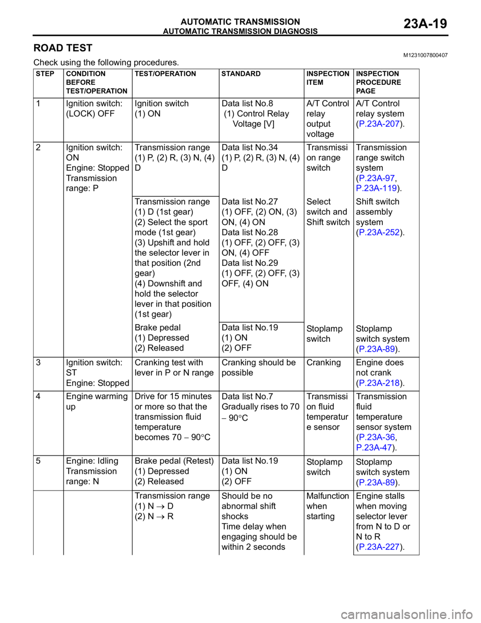
ROAD TESTM1231007800407
Check using the following procedures.
STEP CONDITION
BEFORE
TEST/OPERATIONTEST/OPERATION STANDARD INSPECTION
ITEMINSPECTION
PROCEDURE
PA G E
1 Ignition switch:
(LOCK) OFFIgnition switch
(1) ONData list No.8
(1) Control Relay
Voltage [V]A/T Control
relay
output
voltageA/T Control
relay system
(P.23A-207).
2 Ignition switch:
ON
Engine: Stopped
Transmission
range: PTransmission range
(1) P, (2) R, (3) N, (4)
DData list No.34
(1) P, (2) R, (3) N, (4)
DTransmissi
on range
switchTransmission
range switch
system
(P.23A-97,
P.23A-119).
Transmission range
(1) D (1st gear)
(2) Select the sport
mode (1st gear)
(3) Upshift and hold
the selector lever in
that position (2nd
gear)
(4) Downshift and
hold the selector
lever in that position
(1st gear)Data list No.27
(1) OFF, (2) ON, (3)
ON, (4) ON
Data list No.28
(1) OFF, (2) OFF, (3)
ON, (4) OFF
Data list No.29
(1) OFF, (2) OFF, (3)
OFF, (4) ONSelect
switch and
Shift switchShift switch
assembly
system
(P.23A-252).
Brake pedal
(1) Depressed
(2) ReleasedData list No.19
(1) ON
(2) OFFSto pl amp
switchSt o pla mp
switch system
(P.23A-89).
3 Ignition switch:
ST
Engine: StoppedCranking test with
lever in P or N rangeCranking should be
possibleCranking Engine does
not crank
(P.23A-218).
4 Engine warming
upDrive for 15 minutes
or more so that the
transmission fluid
temperature
becomes 70
90CData list No.7
Gradually rises to 70
90CTransmissi
on fluid
temperatur
e sensorTransmission
fluid
temperature
sensor system
(P.23A-36,
P.23A-47).
5 Engine: Idling
Transmission
range: NBrake pedal (Retest)
(1) Depressed
(2) ReleasedData list No.19
(1) ON
(2) OFFSto pl amp
switchSt o pla mp
switch system
(P.23A-89).
Transmission range
(1) N
D
(2) N
RShould be no
abnormal shift
shocks
Time delay when
engaging should be
within 2 secondsMalfunction
when
startingEngine stalls
when moving
selector lever
from N to D or
N to R
(P.23A-227).
Page 1484 of 1500
AUTOMATIC TRANSMISSION DIAGNOSIS
AUTOMATIC TRANSMISSION23A-25
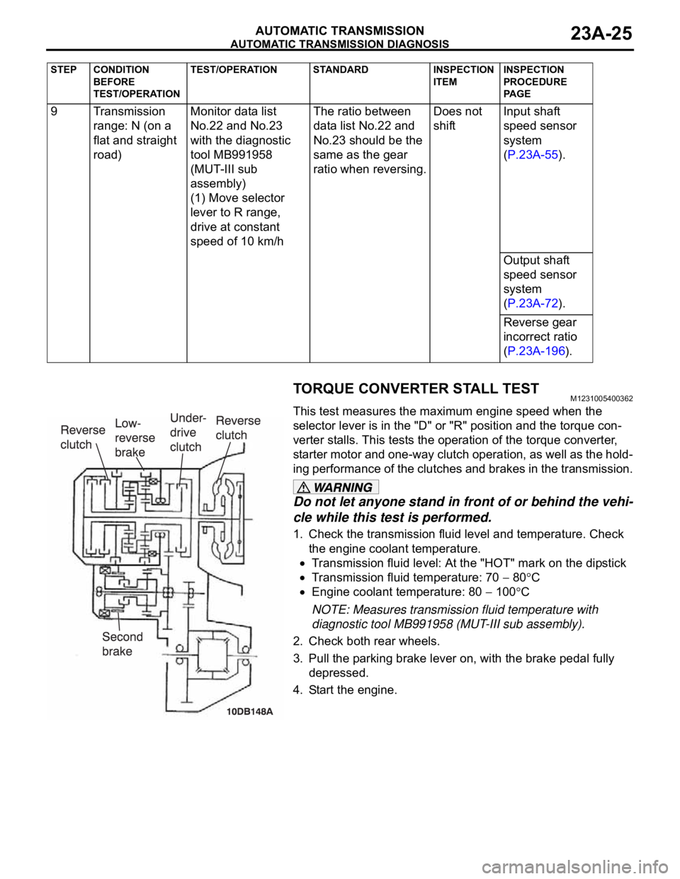
TORQUE CONVERTER STALL TESTM1231005400362
This test measures the maximum engine speed when the
selector lever is in the "D" or "R" position and the torque con-
verter stalls. This tests the operation of the torque converter,
starter motor and one-way clutch operation, as well as the hold-
ing performance of the clutches and brakes in the transmission.
Do not let anyone stand in front of or behind the vehi-
cle while this test is performed.
1. Check the transmission fluid level and temperature. Check
the engine coolant temperature.
Transmission fluid level: At the "HOT" mark on the dipstick
Transmission fluid temperature: 70 80C
Engine coolant temperature: 80 100C
NOTE: Measures transmission fluid temperature with
diagnostic tool MB991958 (MUT-III sub assembly).
2. Check both rear wheels.
3. Pull the parking brake lever on, with the brake pedal fully
depressed.
4. Start the engine. 9 Transmission
range: N (on a
flat and straight
road)Monitor data list
No.22 and No.23
with the diagnostic
tool MB991958
(MUT-III sub
assembly)
(1) Move selector
lever to R range,
drive at constant
speed of 10 km/hThe ratio between
data list No.22 and
No.23 should be the
same as the gear
ratio when reversing.Does not
shiftInput shaft
speed sensor
system
(P.23A-55).
Output shaft
speed sensor
system
(P.23A-72).
Reverse gear
incorrect ratio
(P.23A-196).
STEP CONDITION
BEFORE
TEST/OPERATIONTEST/OPERATION STANDARD INSPECTION
ITEMINSPECTION
PROCEDURE
PA G E
Page 1485 of 1500
AUTOMATIC TRANSMISSION DIAGNOSIS
AUTOMATIC TRANSMISSION23A-26
The throttle should not be fully open for any more than
five seconds.
If you repeat the stall test when the transmission fluid
temperature is greater than 80
C, move the selector
lever to the "N" position and let the engine run at
approximately 1,000 r/min for at least one minute. Wait
until the transmission fluid temperature returns to 80
C
or less.
5. Move the selector lever to the "D" position. Fully depress the
accelerator pedal and read the maximum engine speed at
this time.
Standard value: Stall speed: 2,100
2,600 r/min
6. Move the selector lever to the "R" position. Fully depress the
accelerator pedal and read the maximum engine speed.
Standard value: Stall speed: 2,100
2,600 r/min
TORQUE CONVERTER STALL TEST JUDGMENT
RESULTS
1. Stall speed is too high in both "D" and "R" range
Malfunction of the torque converter (Slippage on the splines
of the torque converter and the input shaft)
Low line pressure
Low-reverse brake slippage and malfunction of the one-way
clutch
2. Stall speed is too high in "D" range only
Underdrive clutch slippage
3. Stall speed is too high in "R" range only
Reverse clutch slippage
4. Stall speed is too low in both "D" and "R" ranges
Malfunction of the torque converter (Slippage of the
one-way clutch)
Insufficient engine output
HYDRAULIC PRESSURE TESTSM1231005500392
The transmission fluid temperature should be between 70
80C during the test.
1. Check the transmission fluid level and temperature. Check
engine coolant temperature.
Transmission fluid level: "HOT" mark on the dipstick
Transmission fluid temperature: 70 80C
Engine coolant temperature: 80 100C
2. Raise the vehicle so that the wheels are free to turn.