service indicator MITSUBISHI 380 2005 Workshop Manual
[x] Cancel search | Manufacturer: MITSUBISHI, Model Year: 2005, Model line: 380, Model: MITSUBISHI 380 2005Pages: 1500, PDF Size: 47.87 MB
Page 919 of 1500
ENGINE COOLING DIAGNOSIS
ENGINE COOLING14-4
INSPECTION PROCEDURE 2: Engine Overheating
DIAGNOSIS
STEP 1. Remove the radiator cap and check for coolant
contamination.
Q: Is the coolant contaminated with rust and oil?
YES : Replace it. Refer to P.14-27.
NO : There is no action to be taken. Go to Step 2.
STEP 2. Check the radiator cap valve opening pressure.
NOTE: Be sure that the cap is clean before testing. Rust or
other foreign material on the cap seal will cause an improper
reading.
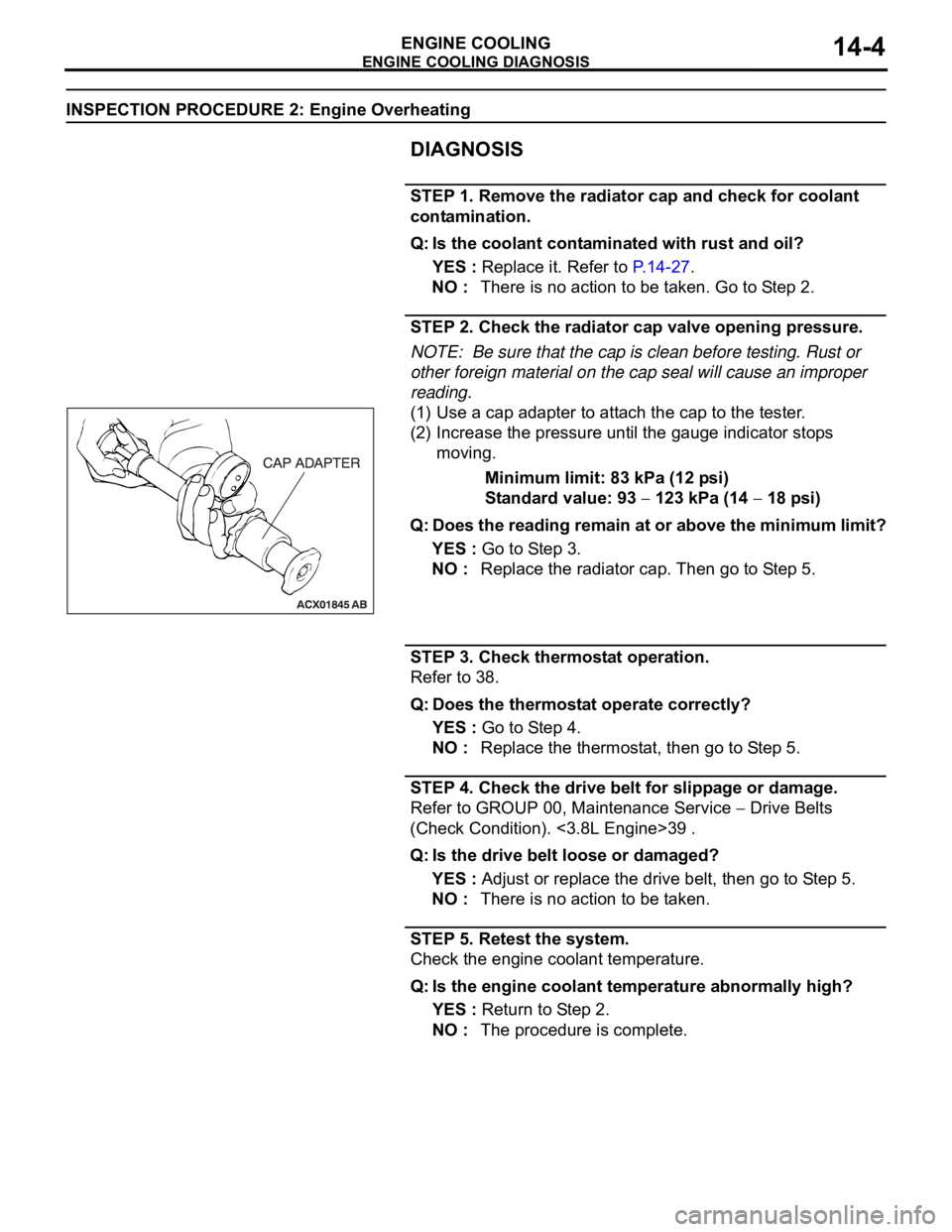
(1) Use a cap adapter to attach the cap to the tester.
(2) Increase the pressure until the gauge indicator stops
moving.
Minimum limit: 83 kPa (12 psi)
Standard value: 93
123 kPa (14 18 psi)
Q: Does the reading remain at or above the minimum limit?
YES : Go to Step 3.
NO : Replace the radiator cap. Then go to Step 5.
STEP 3. Check thermostat operation.
Refer to 38.
Q: Does the thermostat operate correctly?
YES : Go to Step 4.
NO : Replace the thermostat, then go to Step 5.
STEP 4. Check the drive belt for slippage or damage.
Refer to GROUP 00, Maintenance Service
Drive Belts
(Check Condition). <3.8L Engine>39 .
Q: Is the drive belt loose or damaged?
YES : Adjust or replace the drive belt, then go to Step 5.
NO : There is no action to be taken.
STEP 5. Retest the system.
Check the engine coolant temperature.
Q: Is the engine coolant temperature abnormally high?
YES : Return to Step 2.
NO : The procedure is complete.
Page 942 of 1500
ON-VEHICLE SERVICE
ENGINE COOLING14-27
RADIATOR CAP PRESSURE CHECKM1141001300419
NOTE: Be sure that the cap is clean before testing. Rust or
other foreign material on the cap seal will cause an improper
reading.
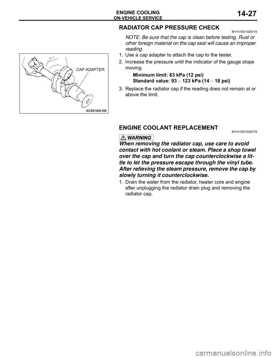
1. Use a cap adapter to attach the cap to the tester.
2. Increase the pressure until the indicator of the gauge stops
moving.
Minimum limit: 83 kPa (12 psi)
Standard value: 93
123 kPa (14 18 psi)
3. Replace the radiator cap if the reading does not remain at or
above the limit.
ENGINE COOLANT REPLACEMENTM1141001200478
When removing the radiator cap, use care to avoid
contact with hot coolant or steam. Place a shop towel
over the cap and turn the cap counterclockwise a lit-
tle to let the pressure escape through the vinyl tube.
After relieving the steam pressure, remove the cap by
slowly turning it counterclockwise.
1. Drain the water from the radiator, heater core and engine
after unplugging the radiator drain plug and removing the
radiator cap.
Page 1244 of 1500

PRECAUTIONS BEFORE SERVICE
GENERAL00-23
HOW TO PERFORM VEHICLE IDENTIFICATION
NUMBER (VIN) WRITING
M1001011400063
The Vehicle Identification Number (VIN) is stored in the ECU by
the vehicle manufacture. If the VIN to be stored in the ECU is
eliminated fraudulently, the Malfunction Indicator Lamp (Check
Engine Lamp) illuminates and Diagnostic Trouble Code (DTC)
No.P0630 (VIN malfunction) is shown. When the ECU is
replaced, and entry of the VIN necessary due to DTC No.
P0630 (VIN malfunction). Enter the VIN in accordance with the
procedure as follows:
.
WRITING PROCEDURE
Required Special Tools:
Diagnostic Tool (MUT-III)
MB991824: V.C.I.
MB991827: MUT-III USB Cable
MB991910: MUT-III Main Harness A (BLUE)
To prevent damage to DIAGNOSTIC TOOL (MUT-III), always
turn the ignition switch to the "LOCK" (OFF) position
before connecting or disconnecting.
1. Connect Diagnostic Tool to the data link connector.
2. Turn the ignition switch to the "ON" position.
3. Confirm DTC No.P0630 (EEPROM malfunction) is not
shown.
NOTE: When DTC No. P0630 (EEPROM malfunction) is
shown, the VIN cannot be stored even if entered. Therefore,
the troubleshooting is performed when this DTC is shown.
4. Select "Coding" form the menu screen.
5. Select "VIN writing" form the menu screen.
6. Enter the VIN.
7. After entry of the VIN, turn the ignition switch to the "LOCK"
(OFF) position. After ten seconds or more passed, turn to
the "ON" position again.
8. Confirm DTC No.P0630 (VIN malfunction) is not shown.
NOTE: When DTC No.P0630 (VIN malfunction) is shown,
enter the VIN again because that would be not appropriate.
Page 1280 of 1500

13C-1
GROUP 13C
TRACTION
CONTROL SYSTEM
(TCL)
CONTENTS
GENERAL DESCRIPTION. . . . . . . . .13C-2
TRACTION CONTROL SYSTEM (TCL)
DIAGNOSIS . . . . . . . . . . . . . . . . . . . .13C-3
INTRODUCTION TO TRACTION CONTROL
SYSTEM (TCL) DIAGNOSIS . . . . . . . . . . . 13C-3
TROUBLESHOOTING STRATEGY . . . . . . 13C-3
DIAGNOSIS FUNCTION. . . . . . . . . . . . . . . 13C-3
DIAGNOSTIC TROUBLE CODE CHART . . 13C-8
DIAGNOSTIC TROUBLE CODE
PROCEDURES . . . . . . . . . . . . . . . . . . . . . . 13C-10
SYMPTOM CHART. . . . . . . . . . . . . . . . . . . 13C-23
SYMPTOM PROCEDURES . . . . . . . . . . . . 13C-23
DATA LIST REFERENCE TABLE . . . . . . . 13C-36
ACTUATOR TEST REFERENCE TABLE. . 13C-37
CHECK AT ABS/TCL-ECU RESISTANCE
AND TERMINAL VOLTAGE . . . . . . . . . . . . 13C-38RESISTANCE AND CONTINUITY
BETWEEN ABS-ECU AND WHEEL SPEED
SENSOR . . . . . . . . . . . . . . . . . . . . . . . . . . . 13C-39
VOLTAGE AND SIGNAL CHECK AT
ABS-ECU USING AN OSCILLOSCOPE . . . 13C-41
SPECIAL TOOLS . . . . . . . . . . . . . . . .13C-45
ON-VEHICLE SERVICE . . . . . . . . . . .13C-47
TCL INDICATOR LIGHT CHECK . . . . . . . . 13C-47
TCL OPERATION CHECK . . . . . . . . . . . . . 13C-47
TCL SWITCH CHECK . . . . . . . . . . . . . . . . . 13C-48
WHEEL SPEED SENSOR CHECK . . . . . . . 13C-48
TCL SWITCH . . . . . . . . . . . . . . . . . . .13C-49
REMOVAL AND INSTALLATION . . . . . . . . 13C-49
WHEEL SPEED SENSOR . . . . . . . . .13C-49
REMOVAL AND INSTALLATION . . . . . . . . 13C-49
ABS/TCL-ECU . . . . . . . . . . . . . . . . . .13C-49
REMOVAL AND INSTALLATION . . . . . . . . 13C-49
Page 1326 of 1500
ON-VEHICLE SERVICE
TRACTION CONTROL SYSTEM (TCL)13C-47
ON-VEHICLE SERVICE
TCL INDICATOR LIGHT CHECKM1136000900058
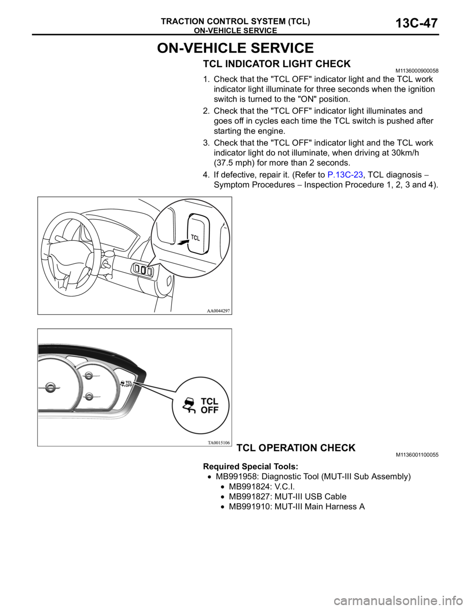
1. Check that the "TCL OFF" indicator light and the TCL work
indicator light illuminate for three seconds when the ignition
switch is turned to the "ON" position.
2. Check that the "TCL OFF" indicator light illuminates and
goes off in cycles each time the TCL switch is pushed after
starting the engine.
3. Check that the "TCL OFF" indicator light and the TCL work
indicator light do not illuminate, when driving at 30km/h
(37.5 mph) for more than 2 seconds.
4. If defective, repair it. (Refer to P.13C-23, TCL diagnosis
Symptom Procedures
Inspection Procedure 1, 2, 3 and 4).
TCL OPERATION CHECKM1136001100055
Required Special Tools:
MB991958: Diagnostic Tool (MUT-III Sub Assembly)
MB991824: V.C.I.
MB991827: MUT-III USB Cable
MB991910: MUT-III Main Harness A
Page 1395 of 1500
AUTO-CRUISE CONTROL
ENGINE AND EMISSION CONTROL17-64
STEP 2. Using Diagnostic Tool MB991958, read the MPI
diagnostic trouble code.
To prevent damage to Diagnostic Tool MB991958, always
turn the ignition switch to the "LOCK" (OFF) position
before connecting or disconnecting Diagnostic Tool
MB991958.
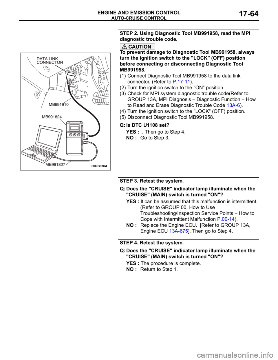
(1) Connect Diagnostic Tool MB991958 to the data link
connector. (Refer to P.17-11).
(2) Turn the ignition switch to the "ON" position.
(3) Check for MPI system diagnostic trouble code(Refer to
GROUP 13A, MPI Diagnosis
Diagnostic Function How
to Read and Erase Diagnostic Trouble Code 13A-6).
(4) Turn the ignition switch to the "LOCK" (OFF) position.
(5) Disconnect Diagnostic Tool MB991958.
Q: Is DTC U1108 set?
YES : . Then go to Step 4.
NO : Go to Step 3.
STEP 3. Retest the system.
Q: Does the "CRUISE" indicator lamp illuminate when the
"CRUISE" (MAIN) switch is turned "ON"?
YES : It can be assumed that this malfunction is intermittent.
(Refer to GROUP 00, How to Use
Troubleshooting/Inspection Service Points
How to
Cope with Intermittent Malfunction P.00-14).
NO : Replace the Engine ECU. [Refer to GROUP 13A,
Engine ECU 13A-675]. Then go to Step 4.
STEP 4. Retest the system.
Q: Does the "CRUISE" indicator lamp illuminate when the
"CRUISE" (MAIN) switch is turned "ON"?
YES : The procedure is complete.
NO : Return to Step 1.
Page 1402 of 1500
AUTO-CRUISE CONTROL
ENGINE AND EMISSION CONTROL17-71
ON-VEHICLE SERVICE
AUTO-CRUISE CONTROL SWITCH CHECKM1172001200054
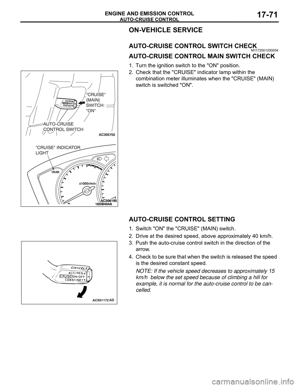
AUTO-CRUISE CONTROL MAIN SWITCH CHECK
1. Turn the ignition switch to the "ON" position.
2. Check that the "CRUISE" indicator lamp within the
combination meter illuminates when the "CRUISE" (MAIN)
switch is switched "ON".
AUTO-CRUISE CONTROL SETTING
1. Switch "ON" the "CRUISE" (MAIN) switch.
2. Drive at the desired speed, above approximately 40 km/h.
3. Push the auto-cruise control switch in the direction of the
arrow.
4. Check to be sure that when the switch is released the speed
is the desired constant speed.
NOTE: If the vehicle speed decreases to approximately 15
km/h below the set speed because of climbing a hill for
example, it is normal for the auto-cruise control to be can-
celled.
Page 1407 of 1500
EMISSION CONTROL
ENGINE AND EMISSION CONTROL17-76
EMISSION CONTROL
GENERAL DESCRIPTIONM1173000100314
The emission control system consists of the fol-
lowing subsystems:
Positive crankcase ventilation system
Evaporative emission system
Exhaust emission control system
DIAGNOSISM1173000700112
SPECIAL TOOLSM1173000600193
SYMPTOM PROBABLE CAUSE REMEDY
Engine will not start or hard
to startVacuum hose disconnected or damaged Repair or replace
Malfunction of the evaporative emission
purge solenoidRepair or replace
Rough idle or engine stalls
Vacuum hose disconnected or damaged. Repair or replace
Malfunction of the positive crankcase
ventilation valveReplace
Malfunction of the purge control system Check the system; If there is a
problem, check its component
parts.
Excessive oil consumption Positive crankcase ventilation line
cloggedCheck positive crankcase
ventilation system
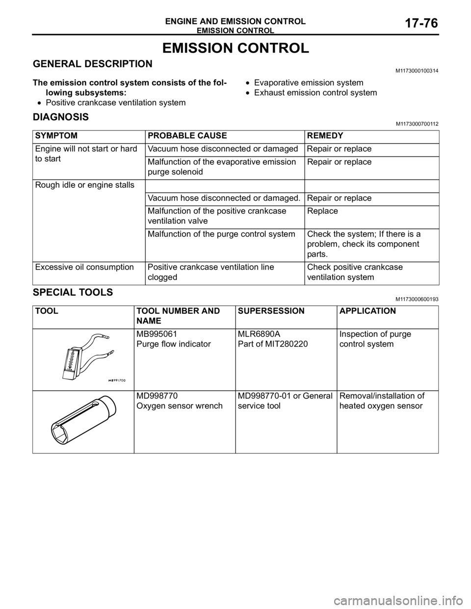
TOOL TOOL NUMBER AND
NAMESUPERSESSION APPLICATION
MB995061
Purge flow indicatorMLR6890A
Part of MIT280220Inspection of purge
control system
MD998770
Oxygen sensor wrenchMD998770-01 or General
service toolRemoval/installation of
heated oxygen sensor
Page 1472 of 1500
AUTOMATIC TRANSMISSION DIAGNOSIS
AUTOMATIC TRANSMISSION23A-13
A/T DIAGNOSTIC TROUBLESHOOTING STRATEGYM1231007600339
Use these steps to plan your diagnostic strategy. If
you follow them carefully, you will find most A/T mal-
functions.
1. Gather as much information as possible about the
complaint from the customer.
2. Verify that the condition described by the
customer exists.
3. Check the vehicle for any A/T Diagnostic Trouble
Codes (DTCs).
4. If you can not verify the condition and there are no
DTCs, the malfunction is intermittent. For
information on how to cope with intermittent
malfunctions, refer to GROUP 00, How to Use
Troubleshooting/Inspection Service Points
How
to Cope with Intermittent Malfunction P.00-14.
5. If you can verify the condition but there are no
DTCs, or the system can not communicate with
diagnostic tool, refer to the Symptom Chart
P.23A-35.6. If there is a DTC, record the number of the code,
then erase the code from memory using
diagnostic tool.
7. Reconfirm the symptom with a Road Test.
8. If a DTC is set again, go to the Inspection Chart
for Diagnostic Trouble Codes.
9. If a DTC is not set again, the malfunction is
intermittent. For information on how to cope with
intermittent malfunctions, refer to GROUP 00,
How to Use Troubleshooting/Inspection Service
Points
How to Cope with Intermittent
Malfunction P.00-14.
10.After repairs are completed, conduct a Road Test
duplicating the complaint conditions to confirm the
malfunction has been eliminated.
DIAGNOSTIC FUNCTIONM1231022500135
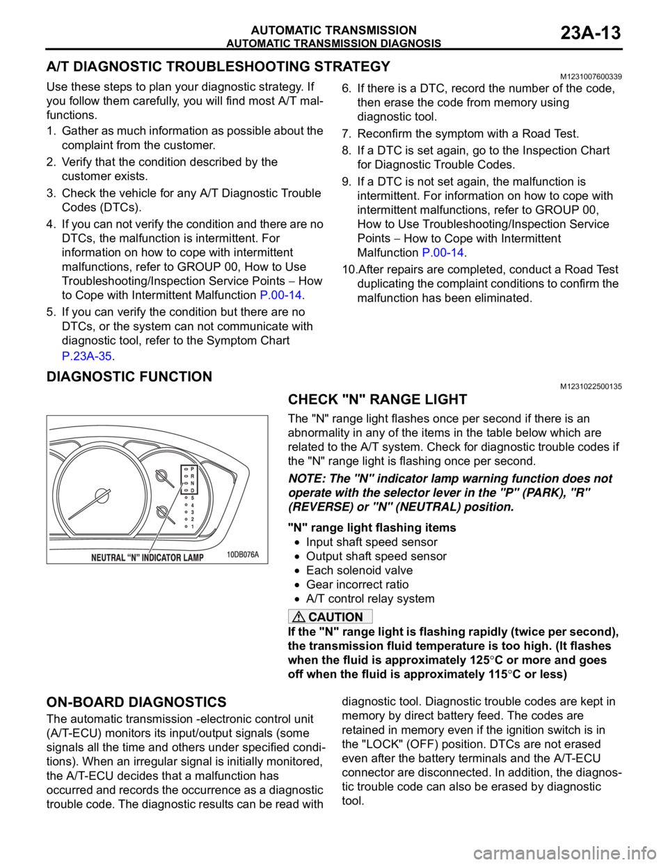
CHECK "N" RANGE LIGHT
The "N" range light flashes once per second if there is an
abnormality in any of the items in the table below which are
related to the A/T system. Check for diagnostic trouble codes if
the "N" range light is flashing once per second.
NOTE: The "N" indicator lamp warning function does not
operate with the selector lever in the "P" (PARK), "R"
(REVERSE) or "N" (NEUTRAL) position.
"N" range light flashing items
Input shaft speed sensor
Output shaft speed sensor
Each solenoid valve
Gear incorrect ratio
A/T control relay system
If the "N" range light is flashing rapidly (twice per second),
the transmission fluid temperature is too high. (It flashes
when the fluid is approximately 125
C or more and goes
off when the fluid is approximately 115
C or less)
ON-BOARD DIAGNOSTICS
The automatic transmission -electronic control unit
(A/T-ECU) monitors its input/output signals (some
signals all the time and others under specified condi-
tions). When an irregular signal is initially monitored,
the A/T-ECU decides that a malfunction has
occurred and records the occurrence as a diagnostic
trouble code. The diagnostic results can be read with diagnostic tool. Diagnostic trouble codes are kept in
memory by direct battery feed. The codes are
retained in memory even if the ignition switch is in
the "LOCK" (OFF) position. DTCs are not erased
even after the battery terminals and the A/T-ECU
connector are disconnected. In addition, the diagnos-
tic trouble code can also be erased by diagnostic
tool.