tow MITSUBISHI 380 2005 Workshop Manual
[x] Cancel search | Manufacturer: MITSUBISHI, Model Year: 2005, Model line: 380, Model: MITSUBISHI 380 2005Pages: 1500, PDF Size: 47.87 MB
Page 531 of 1500
Page 533 of 1500
FRONT SEAT TRIM COVER
INTERIOR52A-44
FITMENT
.
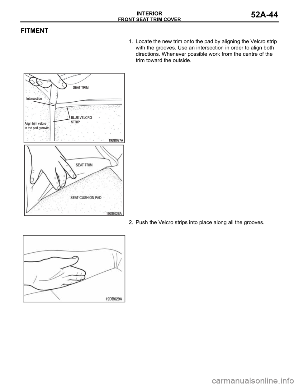
1. Locate the new trim onto the pad by aligning the Velcro strip
with the grooves. Use an intersection in order to align both
directions. Whenever possible work from the centre of the
trim toward the outside.
2. Push the Velcro strips into place along all the grooves.
Page 536 of 1500
REAR SEAT CUSHION TRIM COVER
INTERIOR52A-47
REAR SEAT CUSHION TRIM FITMENT
.
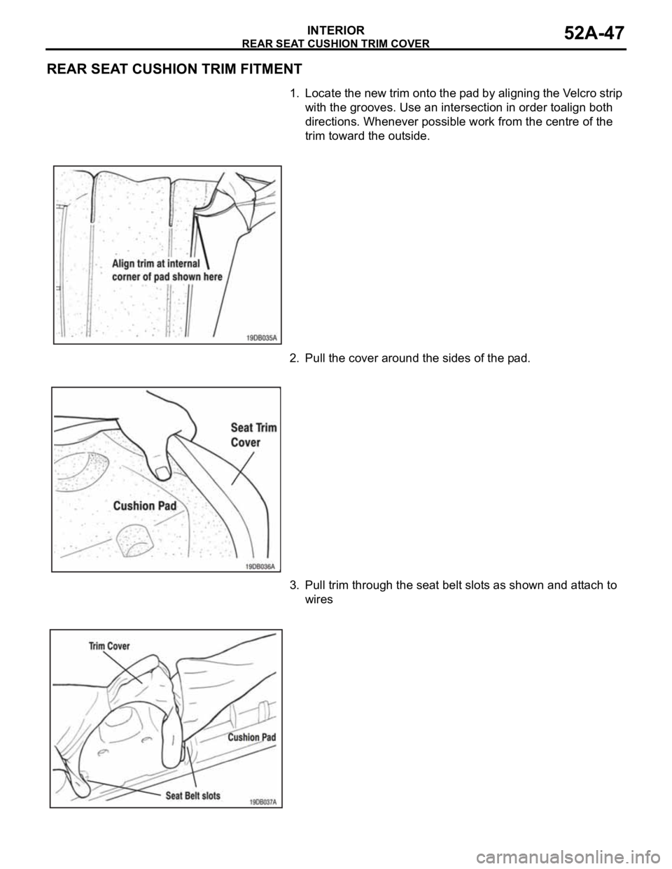
1. Locate the new trim onto the pad by aligning the Velcro strip
with the grooves. Use an intersection in order toalign both
directions. Whenever possible work from the centre of the
trim toward the outside.
2. Pull the cover around the sides of the pad.
3. Pull trim through the seat belt slots as shown and attach to
wires
Page 540 of 1500
REAR SEAT BACK TRIM COVER
INTERIOR52A-51
REAR SEAT BACK TRIM FITMENT
.
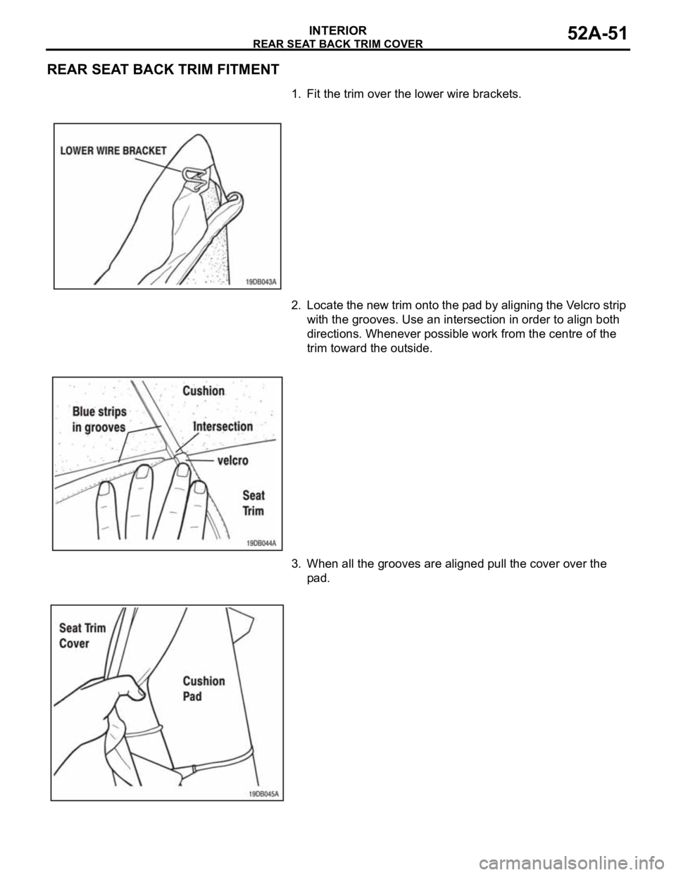
1. Fit the trim over the lower wire brackets.
2. Locate the new trim onto the pad by aligning the Velcro strip
with the grooves. Use an intersection in order to align both
directions. Whenever possible work from the centre of the
trim toward the outside.
3. When all the grooves are aligned pull the cover over the
pad.
Page 852 of 1500
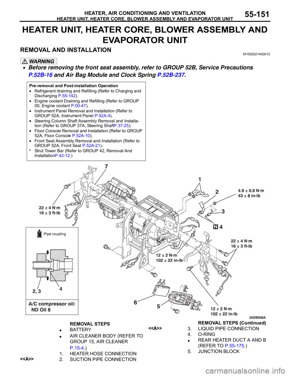
HEATER UNIT, HEATER CORE, BLOWER ASSEMBLY AND EVAPORATOR UNIT
HEATER, AIR CONDITIONING AND VENTILATION55-151
HEATER UNIT, HEATER CORE, BLOWER ASSEMBLY AND
EVAPORATOR UNIT
REMOVAL AND INSTALLATIONM1552021400012
Before removing the front seat assembly, refer to GROUP 52B, Service Precautions
P.52B-16 and Air Bag Module and Clock Spring P.52B-237.
Pre-removal and Post-installation Operation
Refrigerant draining and Refilling (Refer to Charging and
Discharging P.55-142).
Engine coolant Draining and Refilling (Refer to GROUP
00, Engine coolant P.00-47).
Instrument Panel Removal and Installation (Refer to
GROUP 52A, Instrument Panel P.52A-4).
Steering Column Shaft Assembly Removal and Installa-
tion (Refer to GROUP 37A, Steering ShaftP.37-25).
Floor Console Removal and Installation (Refer to GROUP
52A, Floor Console P.52A-10).
Front Seat Assembly Removal and Installation (Refer to
GROUP 52A, Front Seat P.52A-21).
² Strut Tower Bar (Refer to GROUP 42, Removal And
InstallationP.42-12.)
REMOVAL STEPS
BATTERY
AIR CLEANER BODY (REFER TO
GROUP 15, AIR CLEANER
P.15-4.)
1. HEATER HOSE CONNECTION
<>2. SUCTION PIPE CONNECTION
<>3. LIQUID PIPE CONNECTION
4. O-RING
REAR HEATER DUCT A AND B
(REFER TO P.55-175.)
5. JUNCTION BLOCKREMOVAL STEPS (Continued)
Page 869 of 1500
Page 942 of 1500
ON-VEHICLE SERVICE
ENGINE COOLING14-27
RADIATOR CAP PRESSURE CHECKM1141001300419
NOTE: Be sure that the cap is clean before testing. Rust or
other foreign material on the cap seal will cause an improper
reading.
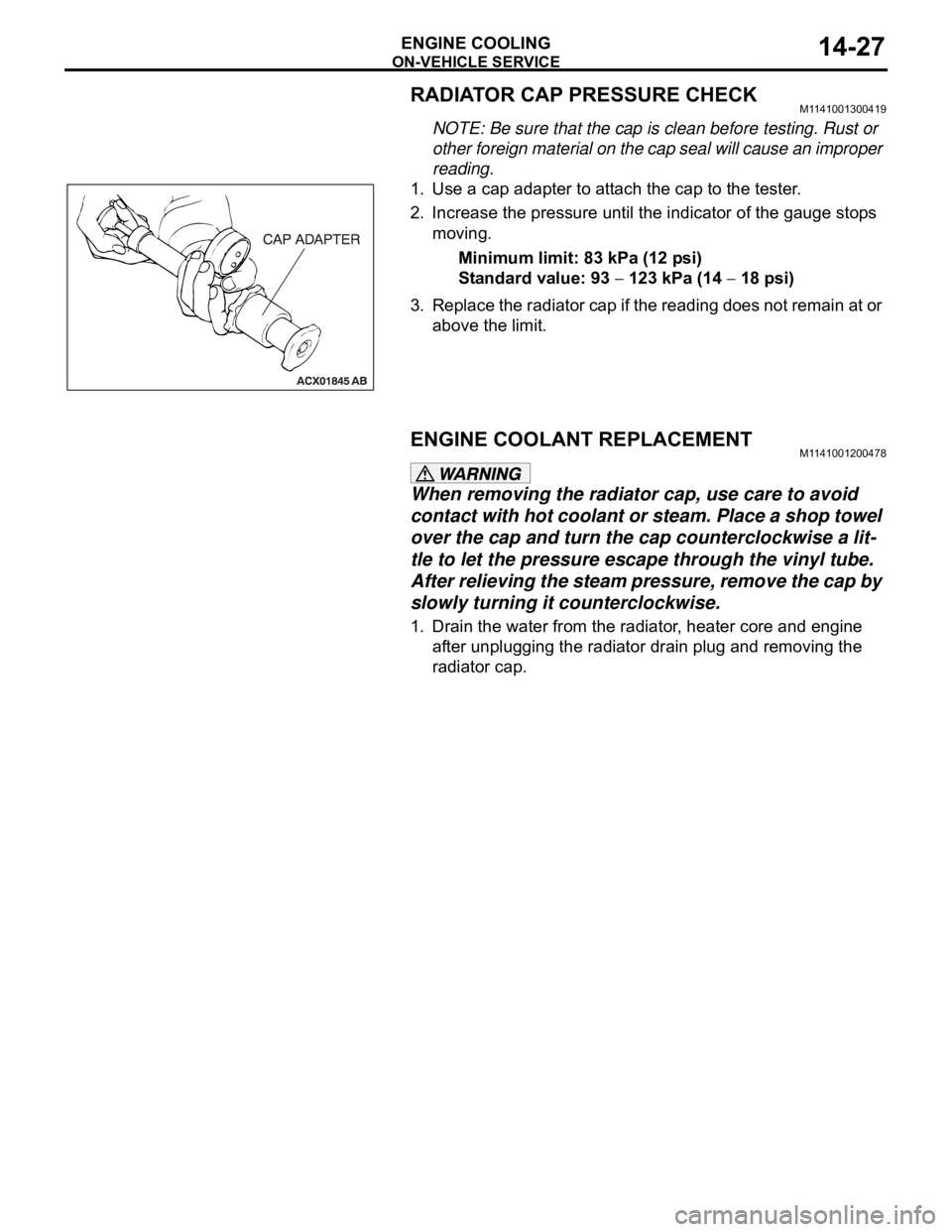
1. Use a cap adapter to attach the cap to the tester.
2. Increase the pressure until the indicator of the gauge stops
moving.
Minimum limit: 83 kPa (12 psi)
Standard value: 93
123 kPa (14 18 psi)
3. Replace the radiator cap if the reading does not remain at or
above the limit.
ENGINE COOLANT REPLACEMENTM1141001200478
When removing the radiator cap, use care to avoid
contact with hot coolant or steam. Place a shop towel
over the cap and turn the cap counterclockwise a lit-
tle to let the pressure escape through the vinyl tube.
After relieving the steam pressure, remove the cap by
slowly turning it counterclockwise.
1. Drain the water from the radiator, heater core and engine
after unplugging the radiator drain plug and removing the
radiator cap.
Page 950 of 1500
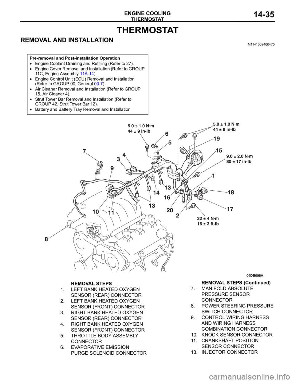
THERMOSTAT
ENGINE COOLING14-35
THERMOSTAT
REMOVAL AND INSTALLATIONM1141002400475
Pre-removal and Post-installation Operation
Engine Coolant Draining and Refilling (Refer to 27).
Engine Cover Removal and Installation (Refer to GROUP
11C, Engine Assembly 11A-14).
Engine Control Unit (ECU) Removal and Installation
(Refer to GROUP 00, General 00-7).
Air Cleaner Removal and Installation (Refer to GROUP
15, Air Cleaner 4).
Strut Tower Bar Removal and Installation (Refer to
GROUP 42, Strut Tower Bar 12).
Battery and Battery Tray Removal and Installation
REMOVAL STEPS
1. LEFT BANK HEATED OXYGEN
SENSOR (REAR) CONNECTOR
2. LEFT BANK HEATED OXYGEN
SENSOR (FRONT) CONNECTOR
3. RIGHT BANK HEATED OXYGEN
SENSOR (REAR) CONNECTOR
4. RIGHT BANK HEATED OXYGEN
SENSOR (FRONT) CONNECTOR
5. THROTTLE BODY ASSEMBLY
CONNECTOR
6. EVAPORATIVE EMISSION
PURGE SOLENOID CONNECTOR7. MANIFOLD ABSOLUTE
PRESSURE SENSOR
CONNECTOR
8. POWER STEERING PRESSURE
SWITCH CONNECTOR
9. CONTROL WIRING HARNESS
AND WIRING HARNESS
COMBINATION CONNECTOR
10. KNOCK SENSOR CONNECTOR
11. CRANKSHAFT POSITION
SENSOR CONNECTOR
13. INJECTOR CONNECTORREMOVAL STEPS (Continued)
Page 964 of 1500
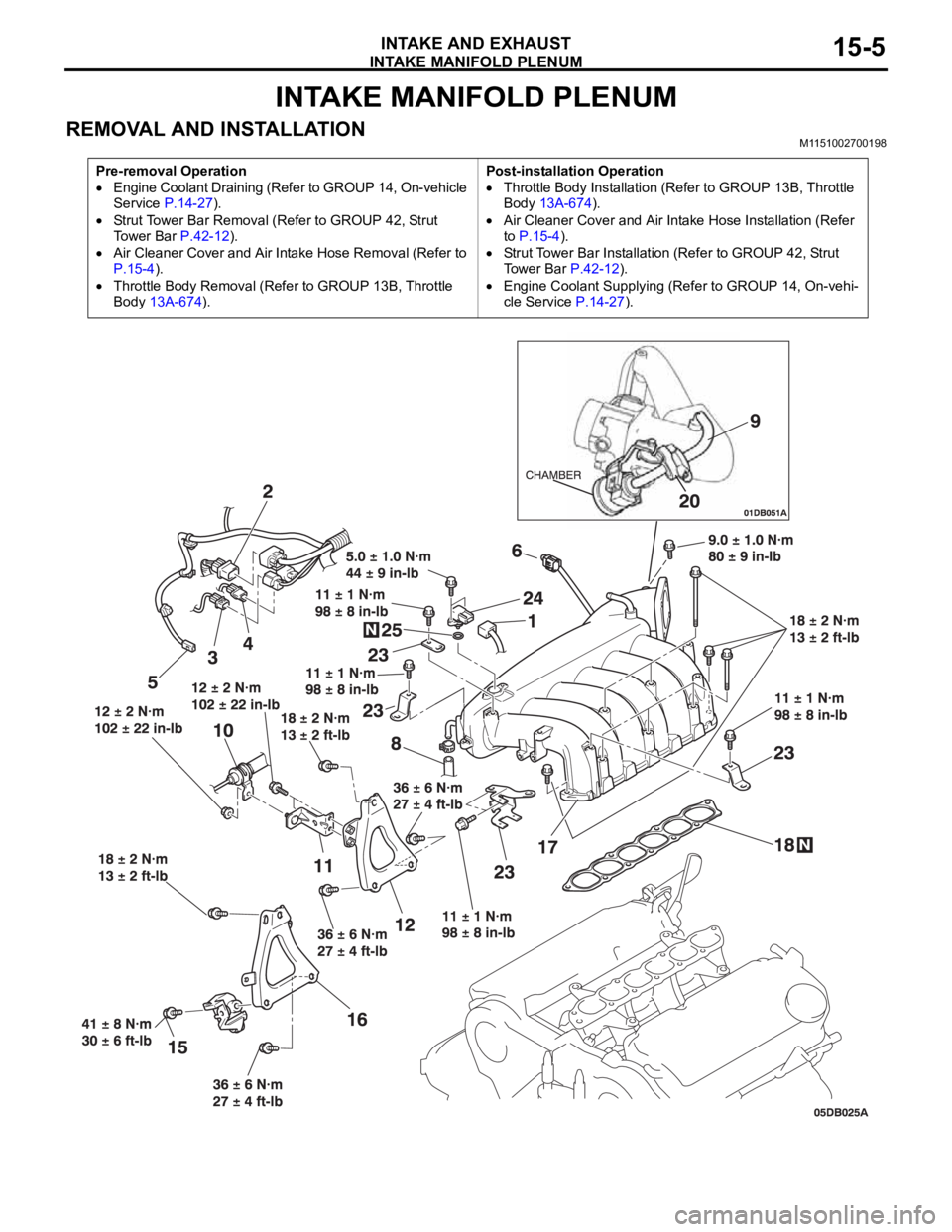
INTAKE MANIFOLD PLENUM
INTAKE AND EXHAUST15-5
INTAKE MANIFOLD PLENUM
REMOVAL AND INSTALLATION M1151002700198
Pre-removal Operation
Engine Coolant Draining (Refer to GROUP 14, On-vehicle
Service P.14-27).
Strut Tower Bar Removal (Refer to GROUP 42, Strut
To w e r B a r P.42-12).
Air Cleaner Cover and Air Intake Hose Removal (Refer to
P.15-4).
Throttle Body Removal (Refer to GROUP 13B, Throttle
Body 13A-674).Post-installation Operation
Throttle Body Installation (Refer to GROUP 13B, Throttle
Body 13A-674).
Air Cleaner Cover and Air Intake Hose Installation (Refer
to P.15-4).
Strut Tower Bar Installation (Refer to GROUP 42, Strut
Tower Bar P.42-12).
Engine Coolant Supplying (Refer to GROUP 14, On-vehi-
cle Service P.14-27).
Page 970 of 1500
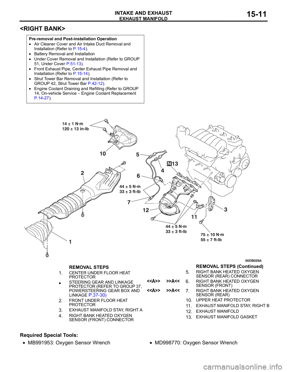
EXHAUST MANIFOLD
INTAKE AND EXHAUST15-11
Required Special Tools:
MB991953: Oxygen Sensor WrenchMD998770: Oxygen Sensor Wrench
Pre-removal and Post-installation Operation
Air Cleaner Cover and Air Intake Duct Removal and
Installation (Refer to P.15-4).
Battery Removal and Installation
Under Cover Removal and Installation (Refer to GROUP
51, Under Cover P.51-13).
Front Exhaust Pipe, Center Exhaust Pipe Removal and
Installation (Refer to P.15-14).
Strut Tower Bar Removal and Installation (Refer to
GROUP 42, Strut Tower Bar P.42-12).
Engine Coolant Draining and Refilling (Refer to GROUP
14, On-vehicle Service Engine Coolant Replacement
P.14-27).
REMOVAL STEPS
1.
CENTER UNDER FLOOR HEAT
PROTECTOR
STEERING GEAR AND LINKAGE
PROTECTOR (REFER TO GROUP 37,
POWERSTEERING GEAR BOX AND
LINKAGE
P.37-30)
2.FRONT UNDER FLOOR HEAT
PROTECTOR
3.EXHAUST MANIFOLD STAY, RIGHT A
4.RIGHT BANK HEATED OXYGEN
SENSOR (FRONT) CONNECTOR
5.RIGHT BANK HEATED OXYGEN
SENSOR (REAR) CONNECTOR
<> >>A<<6.RIGHT BANK HEATED OXYGEN
SENSOR (FRONT)
<> >>A<<7.RIGHT BANK HEATED OXYGEN
SENSOR (REAR)
10.UPPER HEAT PROTECTOR
11 .EXHAUST MANIFOLD STAY, RIGHT B
12.EXHAUST MANIFOLD
13.EXHAUST MANIFOLD GASKET
REMOVAL STEPS (Continued)