tow MITSUBISHI 380 2005 User Guide
[x] Cancel search | Manufacturer: MITSUBISHI, Model Year: 2005, Model line: 380, Model: MITSUBISHI 380 2005Pages: 1500, PDF Size: 47.87 MB
Page 1004 of 1500
Page 1025 of 1500
ENGINE ROLL STOPPER AND CENTREMEMBER
POWER PLANT MOUNT32-8
INSTALLATION SERVICE POINTS
.
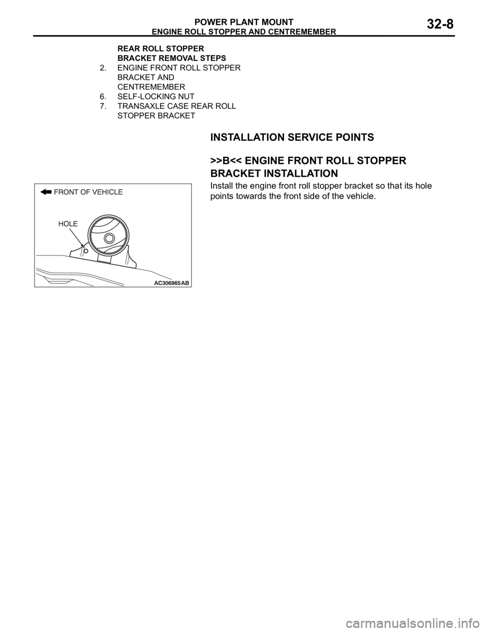
>>B<< ENGINE FRONT ROLL STOPPER
BRACKET INSTALLATION
Install the engine front roll stopper bracket so that its hole
points towards the front side of the vehicle.
2. ENGINE FRONT ROLL STOPPER
BRACKET AND
CENTREMEMBER
6. SELF-LOCKING NUT
7. TRANSAXLE CASE REAR ROLL
STOPPER BRACKET REAR ROLL STOPPER
BRACKET REMOVAL STEPS
Page 1043 of 1500
GARNISHES AND MOLDINGS
EXTERIOR51-10
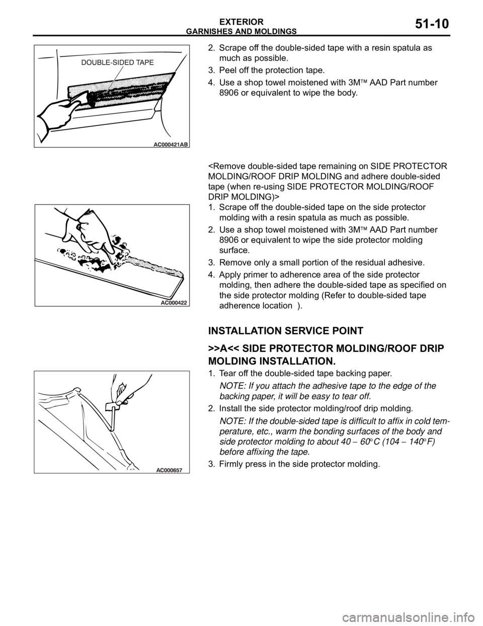
2. Scrape off the double-sided tape with a resin spatula as
much as possible.
3. Peel off the protection tape.
4. Use a shop towel moistened with 3M
AAD Part number
8906 or equivalent to wipe the body.
.
tape (when re-using SIDE PROTECTOR MOLDING/ROOF
DRIP MOLDING)>
1. Scrape off the double-sided tape on the side protector
molding with a resin spatula as much as possible.
2. Use a shop towel moistened with 3M
AAD Part number
8906 or equivalent to wipe the side protector molding
surface.
3. Remove only a small portion of the residual adhesive.
4. Apply primer to adherence area of the side protector
molding, then adhere the double-sided tape as specified on
the side protector molding (Refer to double-sided tape
adherence location ).
INSTALLATION SERVICE POINT
.
>>A<< SIDE PROTECTOR MOLDING/ROOF DRIP
MOLDING INSTALLATION.
1. Tear off the double-sided tape backing paper.
NOTE: If you attach the adhesive tape to the edge of the
backing paper, it will be easy to tear off.
2. Install the side protector molding/roof drip molding.
NOTE: If the double-sided tape is difficult to affix in cold tem-
perature, etc., warm the bonding surfaces of the body and
side protector molding to about 40
60C (104 140F)
before affixing the tape.
3. Firmly press in the side protector molding.
Page 1068 of 1500
42-1
GROUP 42
BODY
CONTENTS
HOOD . . . . . . . . . . . . . . . . . . . . .
42-4
BODY DIAGNOSIS . . . . . . . . . . . .
42-4
INTRODUCTION TO HOOD DIAGNOSIS42-4
HOOD DIAGNOSTIC TROUBLESHOOTING
STRATEGY . . . . . . . . . . . . . . . . . . . . . . 42-4
SYMPTOM CHART . . . . . . . . . . . . . . . . 42-4
SYMPTOM PROCEDURES . . . . . . . . . 42-4
ON-VEHICLE SERVICE. . . . . . . . .42-6
ADJUSTMENT OF CLEARANCE
AROUND HOOD . . . . . . . . . . . . . . . . . . 42-6
ALIGNMENT OF HOOD LATCH AND
STRIKER . . . . . . . . . . . . . . . . . . . . . . . . 42-6
ADJUSTMENT OF HOOD HEIGHT . . . 42-7
HOOD . . . . . . . . . . . . . . . . . . . . . . .42-8
REMOVAL AND INSTALLATION . . . . . 42-8
FENDER . . . . . . . . . . . . . . . . . . .42-10
REMOVAL AND INSTALLATION .
42-10
FUEL FILLER LID . . . . . . . . . . .42-11
REMOVAL AND INSTALLATION .
42-11
STRUT TOWER BAR . . . . . . . . 42-12
REMOVAL AND INSTALLATION .
42-12
WINDOW GLASS . . . . . . . . . . . 42-12
GENERAL . . . . . . . . . . . . . . . . . . . .
42-12
WINDOW GLASS DIAGNOSIS . . .42-14
INTRODUCTION TO WINDOW GLASS
DIAGNOSIS . . . . . . . . . . . . . . . . . . . . . . 42-14
WINDOW GLASS DIAGNOSTIC
TROUBLESHOOTING STRATEGY . . . . 42-14
WINDOW GLASS DIAGNOSTIC TROUBLE
SYMPTOM CHART . . . . . . . . . . . . . . . . 42-14
SYMPTOM PROCEDURES . . . . . . . . . . 42-14
SPECIAL TOOL . . . . . . . . . . . . . . .42-14
WINDSHIELD . . . . . . . . . . . . . . . . .42-15
REMOVAL AND INSTALLATION . . . . . . 42-15
REAR WINDOW GLASS . . . . . . . .42-20
REMOVAL AND INSTALLATION . . . . . . 42-20
Continued on next page
Page 1079 of 1500
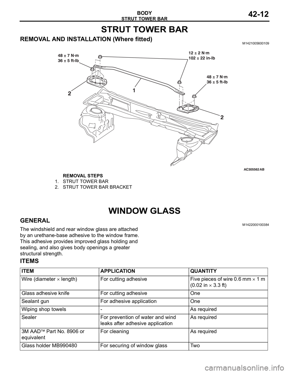
STRUT TOWER BAR
BODY42-12
STRUT TOWER BAR
REMOVAL AND INSTALLATION (Where fitted)M1421005600109
WINDOW GLASS
GENERALM1422000100384
The windshield and rear window glass are attached
by an urethane-base adhesive to the window frame.
This adhesive provides improved glass holding and
sealing, and also gives body openings a greater
structural strength.
ITEMS
REMOVAL STEPS
1. STRUT TOWER BAR
2. STRUT TOWER BAR BRACKET
ITEM APPLICATION QUANTITY
Wire (diameter
length) For cutting adhesive Five pieces of wire 0.6 mm 1 m
(0.02 in
3.3 ft)
Glass adhesive knife For cutting adhesive One
Sealant gun For adhesive application One
Wiping shop towels - As required
Sealer For prevention of water and wind
leaks after adhesive applicationAs required
3M AAD
Part No. 8906 or
equivalentFor cleaning As required
Glass holder MB990480 For securing of window glass Two
Page 1097 of 1500
DOOR
BODY42-30
ON-VEHICLE SERVICE
DOOR FIT ADJUSTMENTM1423001100380
Required Special Tools:
MB990211: Slide Hammer
MB990243: Body Puller
MB990900 or MB991164: Door adjusting Wrench
MB990939: Brass Bar
Attach protection tape to the fender and door edges
where the hinge is installed.
Do not rotate special tool MB991164 with a torque of
over 98 N
m (72 ft-lb).
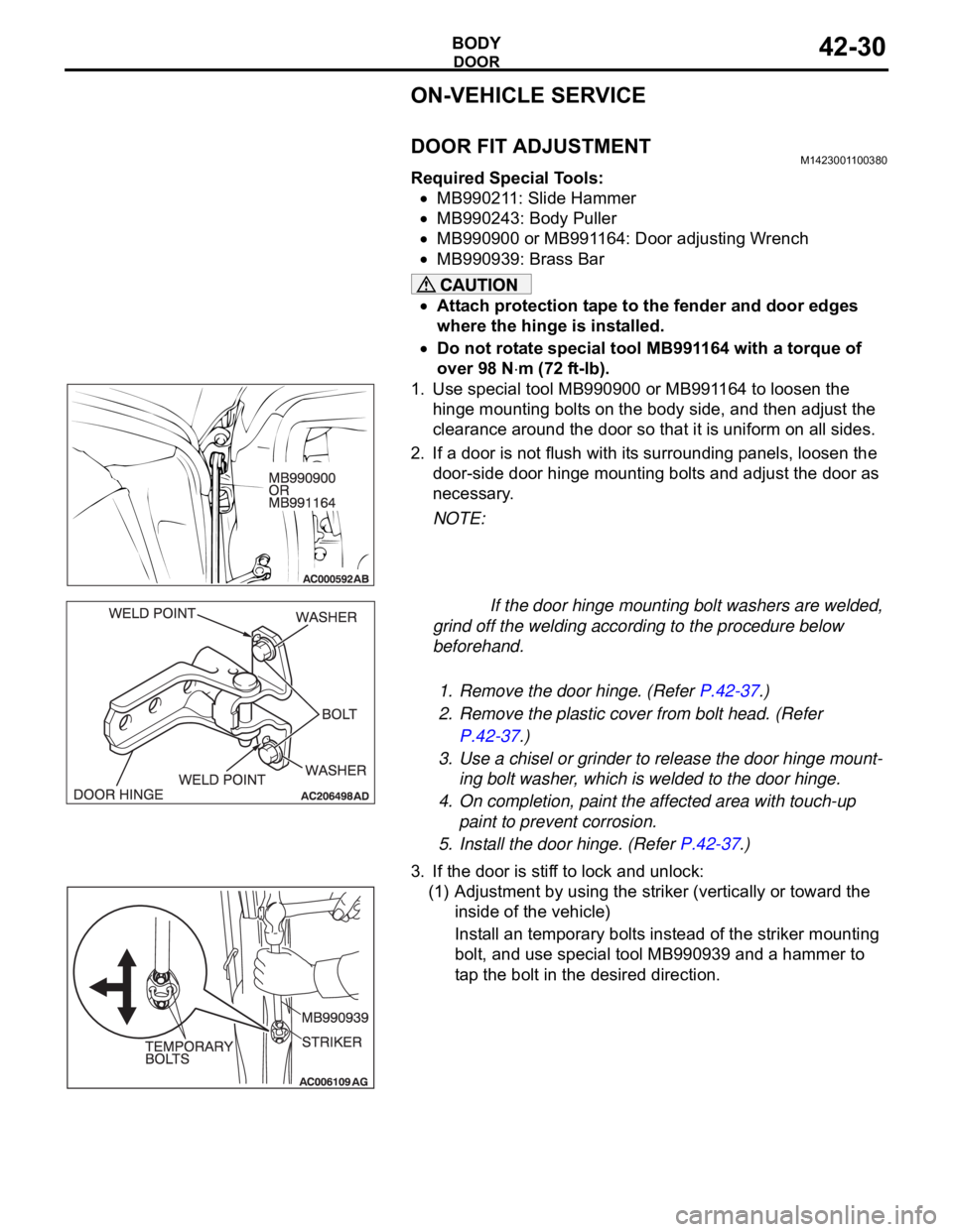
1. Use special tool MB990900 or MB991164 to loosen the
hinge mounting bolts on the body side, and then adjust the
clearance around the door so that it is uniform on all sides.
2. If a door is not flush with its surrounding panels, loosen the
door-side door hinge mounting bolts and adjust the door as
necessary.
NOTE:
If the door hinge mounting bolt washers are welded,
grind off the welding according to the procedure below
beforehand.
.
1. Remove the door hinge. (Refer P.42-37.)
2. Remove the plastic cover from bolt head. (Refer
P.42-37.)
3. Use a chisel or grinder to release the door hinge mount-
ing bolt washer, which is welded to the door hinge.
4. On completion, paint the affected area with touch-up
paint to prevent corrosion.
5. Install the door hinge. (Refer P.42-37.)
3. If the door is stiff to lock and unlock:
(1) Adjustment by using the striker (vertically or toward the
inside of the vehicle)
Install an temporary bolts instead of the striker mounting
bolt, and use special tool MB990939 and a hammer to
tap the bolt in the desired direction.
Page 1098 of 1500
DOOR
BODY42-31
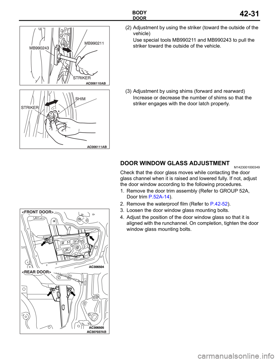
(2) Adjustment by using the striker (toward the outside of the
vehicle)
Use special tools MB990211 and MB990243 to pull the
striker toward the outside of the vehicle.
(3) Adjustment by using shims (forward and rearward)
Increase or decrease the number of shims so that the
striker engages with the door latch properly.
DOOR WINDOW GLASS ADJUSTMENTM1423001000349
Check that the door glass moves while contacting the door
glass channel when it is raised and lowered fully. If not, adjust
the door window according to the following procedures.
1. Remove the door trim assembly (Refer to GROUP 52A,
Door trim P.52A-14).
2. Remove the waterproof film (Refer to P.42-52).
3. Loosen the door window glass mounting bolts.
4. Adjust the position of the door window glass so that it is
aligned with the runchannel. On completion, tighten the door
window glass mounting bolts.
Page 1124 of 1500
DOOR
BODY42-57
INSTALLATION SERVICE POINTS
.
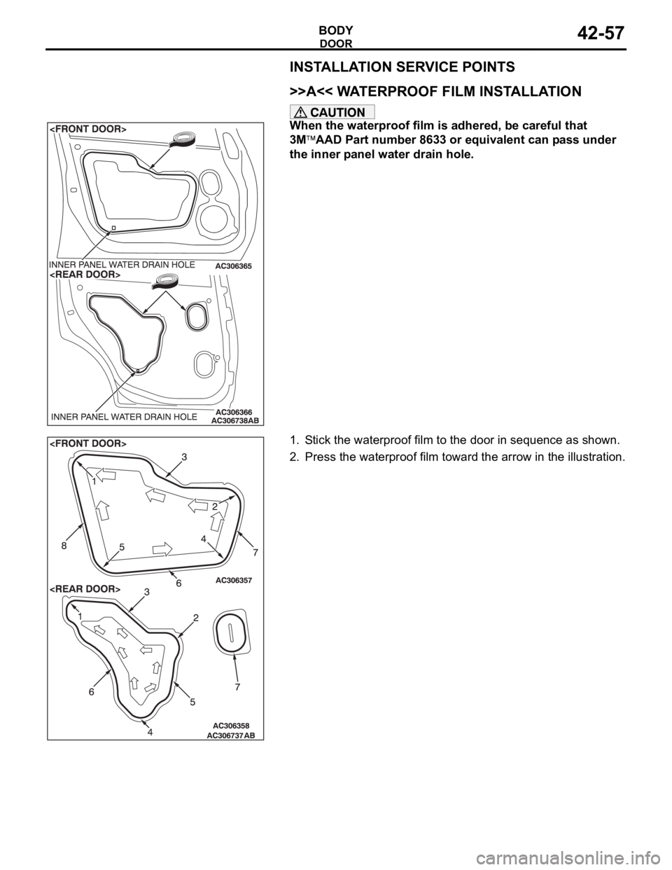
>>A<< WATERPROOF FILM INSTALLATION
When the waterproof film is adhered, be careful that
3M
AAD Part number 8633 or equivalent can pass under
the inner panel water drain hole.
1. Stick the waterproof film to the door in sequence as shown.
2. Press the waterproof film toward the arrow in the illustration.
.
Page 1153 of 1500

SPECIFICATIONS
BODY42-86
SPECIFICATIONS
FASTENER TIGHTENING SPECIFICATIONSM1421005300216
ITEM SPECIFICATION
Hood
Hood hinge bolt (body side) 12
2 Nm (102 22 in-lb)
Hood hinge bolt (hood side) 12
2 Nm (102 22 in-lb)
Hood hinge nut (body side) 12
2 Nm (102 22 in-lb)
Hood latch bolt 9.0
2.0 Nm (80 17 in-lb)
Strut tower bar
Strut tower bar nut 12
2 Nm (102 22 in-lb)
Strut tower bar bracket nut 48
7 Nm (36 5 ft-lb)
Door
Door check bolt (body side) 9.0
2.0 Nm (80 17 in-lb)
Door check bolt (door side) 5.0
1.0 Nm (44 9 in-lb)
Door hinge bolt (body side) 27
5 Nm (20 4 ft-lb)
Door hinge bolt (door side) 21
4 Nm (16 2 ft-lb)
Door outside handle bolt 5.0
1.0 Nm (44 9 in-lb)
Door latch assembly screw 5.9
1.0 Nm (52 9 in-lb)
Door switch screw 3.9
1.0 Nm (35 8 in-lb)
Striker screw 24
3 Nm (18 2 ft-lb)
Trunk lid
Trunk lid hinge bolt (body side) 13
2 Nm ( 111 22 in-lb)
Trunk lid hinge bolt (trunk lid side) 13
2 Nm ( 111 22 in-lb)
Trunk lid hinge nut (trunk lid side) 13
2 Nm ( 111 22 in-lb)
Trunk lid latch bolt 9.0
2.0 Nm (80 17 in-lb)
Trunk lid striker bolt 5.0
1.0 Nm (44 9 in-lb)
Sunroof
Roof lid glass screw 4.0
0.5 Nm (36 4 in-lb)
Sunroof drip plate screw 2.0 N
m (18 in-lb)
Sunroof housing screw 2.0 N
m (18 in-lb)
Sunroof motor bolt 5.4 N
m (48 in-lb)
Loose panel
Cowl top cover outer bolt 11
2 Nm (98 17 in-lb)
Front end structure bar bolt 22
4 Nm (16 2 ft-lb)
12
2 Nm (102 22 in-lb)
11
2 Nm (98 17 in-lb)
Front floor backbone brace bolt 22
4 Nm (16 2 ft-lb)
Upper frame to front pillar brace bolt 22
4 Nm (16 2 ft-lb)
Page 1191 of 1500
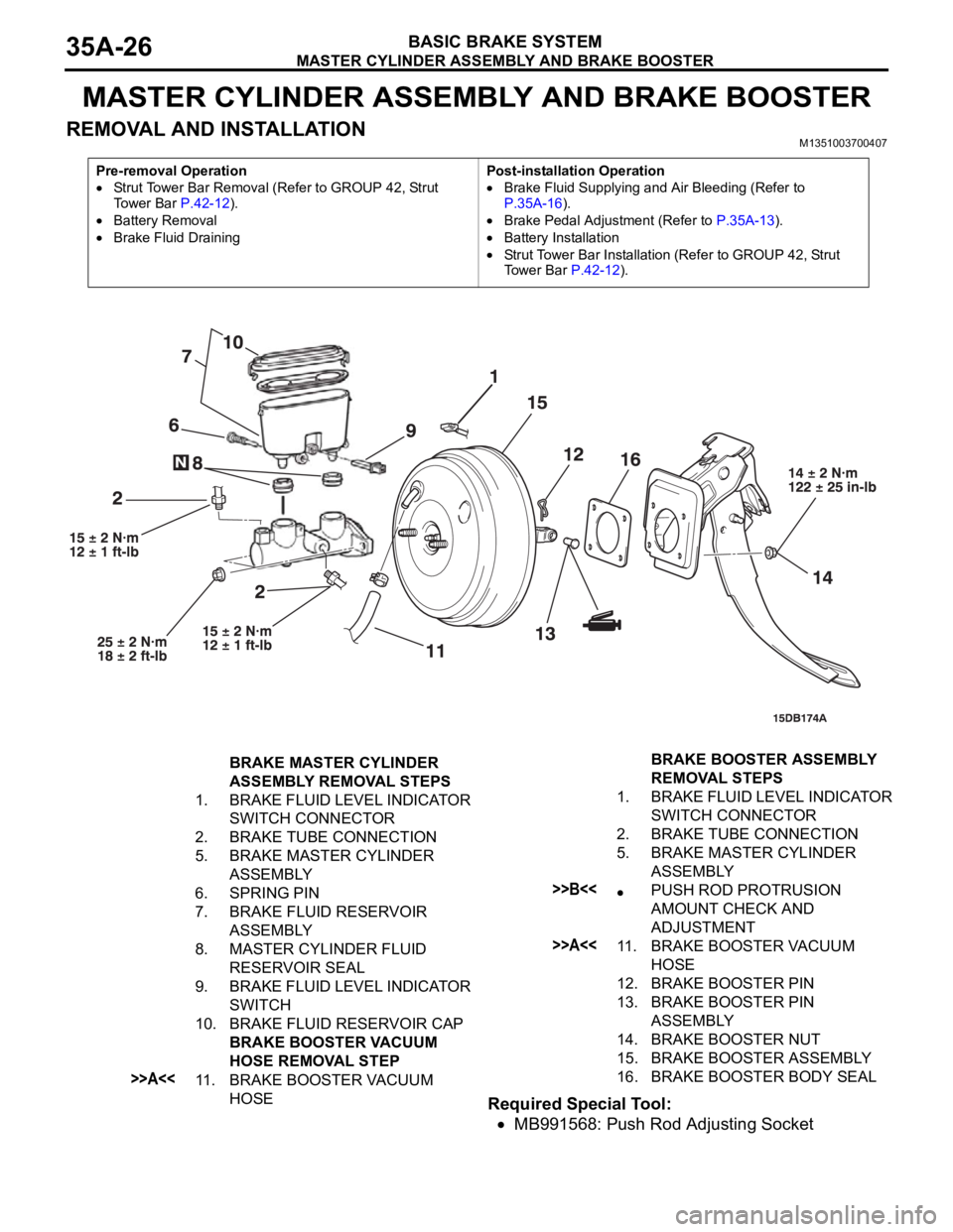
MASTER CYLINDER ASSEMBLY AND BRAKE BOOSTER
BASIC BRAKE SYSTEM35A-26
MASTER CYLINDER ASSEMBLY AND BRAKE BOOSTER
REMOVAL AND INSTALLATIONM1351003700407
Required Special Tool:
MB991568: Push Rod Adjusting Socket
Pre-removal Operation
Strut Tower Bar Removal (Refer to GROUP 42, Strut
To w e r B a r P.42-12).
Battery Removal
Brake Fluid DrainingPost-installation Operation
Brake Fluid Supplying and Air Bleeding (Refer to
P.35A-16).
Brake Pedal Adjustment (Refer to P.35A-13).
Battery Installation
Strut Tower Bar Installation (Refer to GROUP 42, Strut
Tower Bar P.42-12).
BRAKE MASTER CYLINDER
ASSEMBLY REMOVAL STEPS
1. BRAKE FLUID LEVEL INDICATOR
SWITCH CONNECTOR
2. BRAKE TUBE CONNECTION
5. BRAKE MASTER CYLINDER
ASSEMBLY
6. SPRING PIN
7. BRAKE FLUID RESERVOIR
ASSEMBLY
8. MASTER CYLINDER FLUID
RESERVOIR SEAL
9. BRAKE FLUID LEVEL INDICATOR
SWITCH
10. BRAKE FLUID RESERVOIR CAP
BRAKE BOOSTER VACUUM
HOSE REMOVAL STEP
>>A<<11. BRAKE BOOSTER VACUUM
HOSE BRAKE BOOSTER ASSEMBLY
REMOVAL STEPS
1. BRAKE FLUID LEVEL INDICATOR
SWITCH CONNECTOR
2. BRAKE TUBE CONNECTION
5. BRAKE MASTER CYLINDER
ASSEMBLY
>>B<
ADJUSTMENT
>>A<<11. BRAKE BOOSTER VACUUM
HOSE
12. BRAKE BOOSTER PIN
13. BRAKE BOOSTER PIN
ASSEMBLY
14. BRAKE BOOSTER NUT
15. BRAKE BOOSTER ASSEMBLY
16. BRAKE BOOSTER BODY SEAL