fuel MITSUBISHI ASX 2009 1.G Owner's Guide
[x] Cancel search | Manufacturer: MITSUBISHI, Model Year: 2009, Model line: ASX, Model: MITSUBISHI ASX 2009 1.GPages: 368, PDF Size: 8.13 MB
Page 174 of 368

NOTE
l The
gearshift indicator (if so equipped)
shows recommended gearshift points for fuel-
efficient driving. It shows a “ ” when an up-
shift is recommended. Starting and driving
4-22
4
Page 175 of 368

Possible driving speed
E00610801265
Avoid shifting down at high speed, as this may cause excessive engine speed (the tachometer needle into the red zone) and damage the engine.
Petrol-powered vehicles Shift point Speed limit
1600 models 2000 models
1
st
gear 50 km/h (30 mph) 50 km/h (30 mph)2
nd
gear 95 km/h (59 mph) 100 km/h (62 mph)3
rd
gear 140 km/h (87 mph) 140 km/h (87 mph)4
th
gear 190 km/h (118 mph) 185 km/h (115 mph)Use 5
th
gear whenever vehicle speed allows, for maximum fuel economy.
Diesel-powered vehicles Shift point Speed limit
1
st
gear 35 km/h (22 mph)2
nd
gear 65 km/h (40 mph)3
rd
gear 105 km/h (65 mph)4
th
gear 140 km/h (87 mph)5
th
gear 180 km/h (112 mph)Use 6
th
gear whenever vehicle speed allows, for maximum fuel economy. Starting and driving
4-23 4
Page 176 of 368
Automatic transmission
INVECS-III Sports Mode 6CVT
(Intelligent & Innovative Vehicle Electronic Control System III)* E00602100031
The
INVECS-III uses optimization and adaptation
functions to optimally match the gear ratio to driv-
ing and road conditions.
The CVT is capable of changing the gear ratio auto-
matically and steplessly to suit driving conditions
in all phases of vehicle operation. It therefore real-
izes smooth, shock-free operation and excellent
fuel efficiency. CAUTION
l
Automatic
downshifts may not take place
while the CVT fluid is still cool immedi-
ately after you start driving. To cause a
downshift, depress the brake pedal, man-
ually shift down when necessary.
Always strive to drive safely in accord-
ance with road conditions.
Selector lever operation E00602200221
The CVT selects an optimum gear ratio automati-
cally,
depending on the speed of the vehicle and
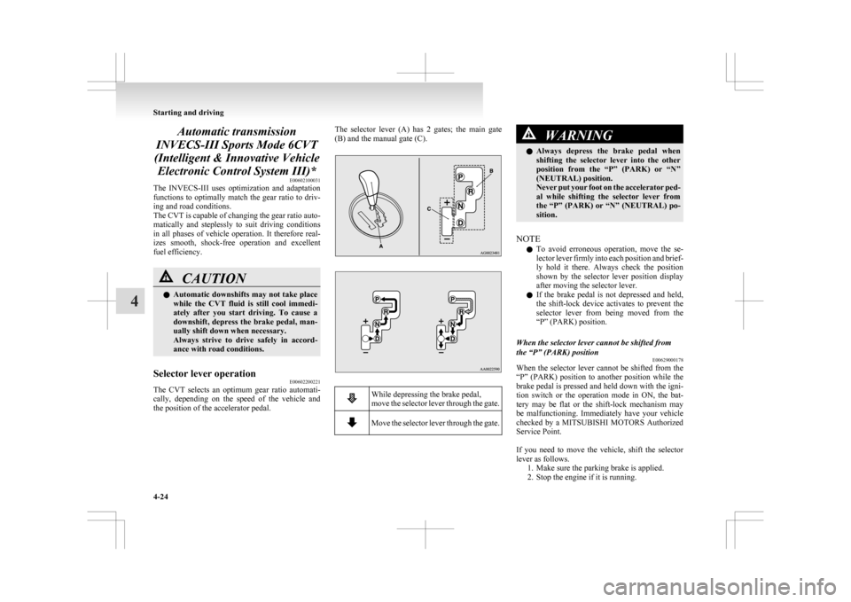
the position of the accelerator pedal. The selector lever (A) has 2 gates; the main gate
(B) and the manual gate (C).
While depressing the brake pedal,
move
the selector lever through the gate. Move the selector lever through the gate. WARNING
l Always
depress the brake pedal when
shifting the selector lever into the other
position from the “P” (PARK) or “N”
(NEUTRAL) position.
Never put your foot on the accelerator ped-
al while shifting the selector lever from
the “P” (PARK) or “N” (NEUTRAL) po-
sition.
NOTE l To
avoid erroneous operation, move the se-
lector lever firmly into each position and brief-
ly hold it there. Always check the position
shown by the selector lever position display
after moving the selector lever.
l If the brake pedal is not depressed and held,
the shift-lock device activates to prevent the
selector lever from being moved from the
“P” (PARK) position.
When the selector lever cannot be shifted from
the “P” (PARK) position E00629000178
When the selector lever cannot be shifted from the
“P”
(PARK) position to another position while the
brake pedal is pressed and held down with the igni-
tion switch or the operation mode in ON, the bat-
tery may be flat or the shift-lock mechanism may
be malfunctioning. Immediately have your vehicle
checked by a MITSUBISHI MOTORS Authorized
Service Point.
If you need to move the vehicle, shift the selector
lever as follows. 1. Make sure the parking brake is applied.
2. Stop the engine if it is running. Starting and driving
4-24
4
Page 181 of 368
Electronically controlled 4WD
system* E00604900280
The
electronically controlled 4WD system is a 4-
wheel drive system that allows one of three drive
modes to be selected with a dial, in accordance
with the driving conditions.
The following drive modes are available. Drive mode Function
2WD This mode is for economical
driving on normal dry roads
and motorway.
Driving in front-wheel drive.
4WD AUTO The default mode.
This mode is for automatical-
ly controlling the distribution
of driving torque to all four
wheels according to the driv-
ing conditions.
4WD LOCK This mode is for driving in
slippery conditions such as
on snow-covered roads or
sand.
The large amount of driving
torque that is applied to the
rear tyres enables getting out
of slippery areas and power-
ful driving is possible across
all ranges.4-wheel drive operation requires special driving
skills.
Carefully
read the “4-wheel drive operation” on
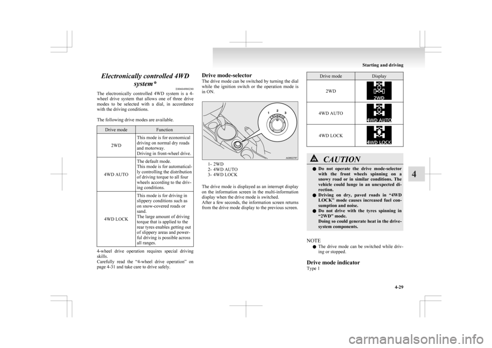
page 4-31 and take care to drive safely. Drive mode-selector
The
drive mode can be switched by turning the dial
while the ignition switch or the operation mode is
in ON. 1- 2WD
2-
4WD AUTO
3- 4WD LOCK
The drive mode is displayed as an interrupt display
on the information screen in the multi-information
display when the drive mode is switched.
After a few seconds, the information screen returns
from the drive mode display to the previous screen. Drive mode Display
2WD 4WD AUTO
4WD LOCK
CAUTION
l
Do not operate the drive mode-selector
with the front wheels spinning on a
snowy road or in similar conditions. The
vehicle could lunge in an unexpected di-
rection.
l Driving on dry, paved roads in “4WD
LOCK” mode causes increased fuel con-
sumption and noise.
l Do not drive with the tyres spinning in
“2WD” mode.
Doing so could generate heat in the drive-
system components.
NOTE l The
drive mode can be switched while driv-
ing or stopped.
Drive mode indicator
Type 1 Starting and driving
4-29 4
Page 183 of 368
4-wheel drive operation
E00606600887
Your
vehicle has been designed primarily for use
on paved roads.
But its unique 4-wheel drive system allows you to
occasionally travel on unpaved roads, to camp-
grounds, picnic sites, and similar locations.
Not only does this ensure better handling on dry,
paved roads but also permits better traction when
driving on slippery, wet or snow-covered roads and
when moving out of mud.
But it is not suitable for heavy off road use or tow-
ing in rough conditions.
It is particularly important to note that 4-wheel
drive may not give sufficient hill climbing ability
and engine braking on steep slopes. You should try
to avoid driving on steep slopes.
Also, you must exercise caution when driving on
sand and mud and when driving through water be-
cause sufficient traction may not be available in cer-
tain circumstances.
Please avoid driving the vehicle through areas
where the tyres may get stuck in deep sand or mud. WARNING
l Do
not over-rely on the 4-wheel drive ve-
hicles. Even 4-wheel drive vehicles have
limits to the system and ability to main-
tain control and traction. Reckless driv-
ing may lead to accidents. Always drive
carefully, taking account of the road con-
ditions.
l Improperly operating this vehicle on or
off-paved roads can cause an accident or
rollover in which you and your passen-
gers could be seriously injured or killed. WARNING
• Follow
all instructions and guidelines in the owner’s manual.
• Keep your speed low and do not drive faster than conditions allow you to.
NOTE l Driving
on rough roads can be hard on a ve-
hicle. Before you leave paved roads, be sure
all scheduled maintenance and service has
been done, and that you have inspected your
vehicle. Pay special attention to the condi-
tion of the tyres, and check the tyre pressures.
l MITSUBISHI MOTORS is not responsible
to the operator for any damage or injury
caused or liability incurred by improper and
negligent operation of a vehicle. All techni-
ques of vehicle operation depend on the skill
and experience of the operator and other par-
ticipating parties. Any deviation from the rec-
ommended operating instructions above is at
their own risk.
l Note that the stopping distance required of a
4-wheel drive vehicle differs very little from
that of a 2-wheel drive vehicle. When driv-
ing on a snow-covered road or a slippery,
muddy surface, make sure that you keep a suf-
ficient distance between your vehicle and the
one ahead of you.
l The driving posture should be more upright;
adjust the seat to a good position for easy
steering and pedal operation. Be sure to wear
the seat belt. l
After
driving on rough roads, check each
part of the vehicle and wash it thoroughly
with water. Refer to the “Inspection and main-
tenance following rough road operation” sec-
tion and “Maintenance” section. CAUTION
l
Setting
the drive mode-selector to “4WD
LOCK” to drive on dry paved road will
increase fuel consumption, with possible
noise generation.
Turning sharp corners
When
turning a sharp corner in “4WD LOCK” po-
sition at low speed, a slight difference in steering
may be experienced similar to as if the brakes were
applied. This is called tight corner braking and re-
sults from each of the 4 tyres being at a different
distance from the corner. The phenomenon is typi-
cal of 4-wheel drive vehicles. If this occurs, either
straighten out the steering wheel, or change to
“2WD” or “4WD AUTO” mode.
On snowy or icy roads
Set the drive mode-selector to “4WD AUTO” or
“4WD LOCK” in accordance with the road condi-
tions, and then gradually depress the accelerator ped-
al for a smooth start.
NOTE
l The use of snow tyres is recommended.
l Maintain a safe distance between vehicles,
avoid sudden braking, and use engine brak-
ing (downshifting). Starting and driving
4-31 4
Page 206 of 368
NOTE
l To
prevent wind noise or reduction in fuel
economy, remove the roof carrier when not
in use.
l Remove the roof carrier before using an auto-
matic car wash.
l Be sure that adequate clearance is main-
tained for raising the tailgate when installing
a roof carrier. Trailer towing
E00610000459
In
order to tow a trailer with your vehicle, have a
trailer towing device that meets all relevant regula-
tions in your area, mounted consult a
MITSUBISHI MOTORS Authorized Service Point.
The regulations concerning the towing of a trailer
may differ from country to country. You are ad-
vised to obey the regulations in each area. CAUTION
l
Danger of Accident!
A
towing bar should be fitted according
to MITSUBISHI MOTORS guidelines.
Maximum towable weight with brake
and maximum trailer-nose weight
Never
exceed the maximum towable weight with
brake and the maximum trailer-nose weight as lis-
ted in the specifications.
(Refer to page 9-07.)
If you tow a trailer at an altitude of more than
1,000 m above sea-level, reduce your weight by
10 % of the gross combination weight for every in-
crease of 1,000 m above sea-level, as the engine out-
put is lowered owing to decrease in atmospheric
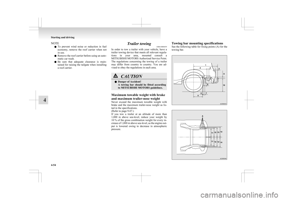
pressure. Towing bar mounting specifications
See
the following table for fixing points (A) for the
towing bar. Starting and driving
4-54
4
Page 308 of 368
Service precautions
E01000100878
Adequate
care of your vehicle at regular intervals
serves to preserve the value and appearance as long
as possible.
Maintenance items as described in this owner’s man-
ual can be performed by the owner.
We recommend you to have the periodic inspection
and maintenance performed by a MITSUBISHI
MOTORS Authorized Service Point or another spe-
cialist.
In the event a malfunction or a problem is discov-
ered, we recommend you to have it checked and re-
paired. This section contains information on inspec-
tion maintenance procedures that you can do your-
self. Follow the instructions and cautions for each
of the various procedures. WARNING
l When
checking or servicing the inside of
the engine compartment, make sure the
engine is switched off and has had a
chance to cool down.
l If it is necessary to do work in the engine
compartment with the engine running, be
especially careful that your clothing, hair,
etc., does not become caught by the fan,
drive belts, or other moving parts.
l The fan may turn on automatically even
if the engine is not running. Turn the igni-
tion switch to the “LOCK” position or
put the operation mode in OFF to be safe
while you work in the engine compart-
ment. WARNING
l Do
not smoke, cause sparks or allow open
flames around fuel or battery. The fumes
are flammable.
l Be extremely cautious when working
around the battery. It contains poisonous
and corrosive sulphuric acid.
l Do not get under your vehicle with just
the body jack supporting it. Always use
automotive jack stands.
l Improper handling of components and
materials used in the vehicle can endan-
ger your personal safety. We recommend
you to consult a specialist for necessary in-
formation. Catalytic converter
E01000200765
The
exhaust gas scavenging devices used with the
catalytic converter are extremely efficient for the re-
duction of noxious gases. The catalytic converter is
installed in the exhaust system.
It is important to keep the engine properly tuned to
ensure proper catalyst operation and prevent possi-
ble catalyst damage. WARNING
l As
with any vehicle, do not park or oper-
ate this vehicle in areas where combusti-
ble materials such as dry grass or leaves
can come in contact with a hot exhaust
since a fire could occur.
l Paint should not be applied to the catalyt-
ic converter.
NOTE l Use
fuel of the type recommended in “Fuel
selection” on page 02. Maintenance
8-02
8
Page 311 of 368
8. After adding oil, close the cap securely.
9.
Confirm the oil level by repeating step 4 to 6. CAUTION
l
In
diesel-powered vehicles, when burning
away and removing soot accumulated in
the DPF, fuel can mix with the engine oil
and an increase in the engine oil level
may occur. This does not indicate an ab-
normality.
However, if the engine oil level is at or
over the “X” mark (B) on the engine oil
dipstick (A), change the engine oil.
MAX. MIN. NOTE
l The
engine oil will deteriorate rapidly if the
vehicle is subjected to severe conditions, re-
quiring earlier oil replacement.
Please refer to the maintenance schedule.
l For information on how to dispose of used en-
gine oil, refer to page 05. Recommended engine oil viscosity
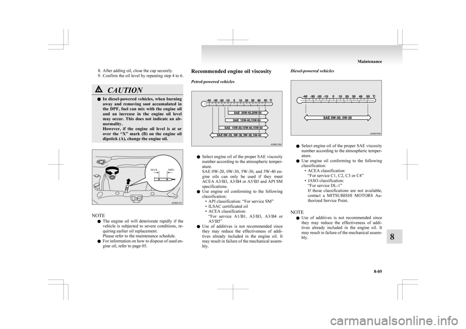
Petrol-powered vehicles
l
Select
engine oil of the proper SAE viscosity
number according to the atmospheric temper-
ature.
SAE 0W-20, 0W-30, 5W-30, and 5W-40 en-
gine oils can only be used if they meet
ACEA A3/B3, A3/B4 or A5/B5 and API SM
specifications.
l Use engine oil conforming to the following
classification:
• API classification: “For service SM”
• ILSAC certificated oil
• ACEA classification:“For service A1/B1, A3/B3, A3/B4 or
A5/B5”
l Use of additives is not recommended since
they may reduce the effectiveness of addi-
tives already included in the engine oil. It
may result in failure of the mechanical assem-
bly. Diesel-powered vehicles
l
Select
engine oil of the proper SAE viscosity
number according to the atmospheric temper-
ature.
l Use engine oil conforming to the following
classification:
• ACEA classification:“For service C1, C2, C3 or C4”
• JASO classification: “For service DL-1”
If those classifications are not available,
contact a MITSUBISHI MOTORS Au-
thorized Service Point.
NOTE l Use of additives is not recommended since
they may reduce the effectiveness of addi-
tives already included in the engine oil. It
may result in failure of the mechanical assem-
bly. Maintenance
8-05 8
Page 323 of 368
General maintenance
E01002700520
Fuel, engine coolant, oil and exhaust
gas leakage
Look
under the body of your vehicle to check for
fuel, engine coolant, oil and exhaust gas leaks. WARNING
l If
you see a suspicious fuel leak or if you
smell fuel, do not operate the vehicle; call
your MITSUBISHI MOTORS Author-
ized Service Point for assistance.
Exterior and interior lamp operation
Operate
the combination lamp switch to check that
all lamps are functioning properly.
If the lamps do not illuminate, the probable cause
is a blown fuse or defective lamp bulb. Check the
fuses first. If there is no blown fuse, check the
lamp bulbs.
For information regarding the inspection and re-
placement of the fuses and the lamp bulbs, refer to
“Fuses” on page 8-18 and “Replacement of lamp
bulbs” on page 8-23.
If the fuses and bulbs are all OK, we recommend
you to have your vehicle checked and repaired.
Meter, gauge and indicator/warning
lamps operation
Start the engine and check the operation of all in-
struments, gauges and indication and warning lamps.
If there is anything wrong, we recommend you to
have your vehicle inspected. Hinges and latches lubrication
Check
all latches and hinges, and, if necessary,
have them lubricated. For cold and snowy weather
E01002800361
Ventilation slots
The
ventilation slots in front of the windscreen
should be kept clear of leaves or brushed clear after
heavy snowfall, so that the operation of the heating
and ventilation systems will not be impaired.
Weatherstripping
To prevent freezing of the weatherstripping on the
doors, bonnet, etc., they should be treated with sili-
cone grease.
Additional equipment
It is a good idea to carry a shovel or a short-han-
dled spade in the vehicle during the winter so that
you can clear away snow if you get stranded. A
small hand-brush for sweeping snow off the vehi-
cle and a plastic scraper for the windscreen and
rear window are also useful. Maintenance
8-17 8
Page 328 of 368
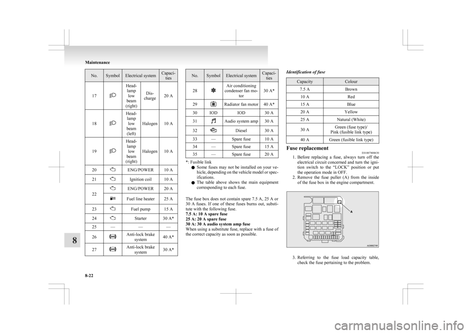
No. Symbol Electrical system Capaci-
ties
17 Head-
lamp low
beam
(right) Dis-
charge 20 A
18 Head-
lamp low
beam (left) Halogen 10 A
19 Head-
lamp low
beam
(right) Halogen 10 A
20 ENG/POWER 10 A
21 Ignition coil 10 A
22 ENG/POWER 20 A
Fuel line heater 25 A
23 Fuel pump 15 A
24 Starter 30 A*
25 — ——
26 Anti-lock brake
system 40 A*
27 Anti-lock brake
system 30 A* No. Symbol Electrical system Capaci-
ties
28 Air conditioning
condenser fan mo- tor 30 A*
29 Radiator fan motor 40 A*
30 IOD IOD 30 A
31 Audio system amp 30 A
32 Diesel 30 A
33 — Spare fuse 10 A
34 — Spare fuse 15 A
35 — Spare fuse 20 A *: Fusible link
l Some
fuses may not be installed on your ve-
hicle, depending on the vehicle model or spec-
ifications.
l The table above shows the main equipment
corresponding to each fuse.
The fuse box does not contain spare 7.5 A, 25 A or
30 A fuses. If one of these fuses burns out, substi-
tute with the following fuse.
7.5 A: 10 A spare fuse
25 A: 20 A spare fuse
30 A: 30 A audio system amp fuse
When using a substitute fuse, replace with a fuse of
the correct capacity as soon as possible. Identification of fuse Capacity Colour
7.5 A Brown
10 A Red
15 A Blue
20 A Yellow
25 A Natural (White)
30 A Green (fuse type)/
Pink (fusible link type)
40 A Green (fusible link type) Fuse replacement
E01007800630
1. Before replacing a fuse, always turn off the
electrical circuit concerned and turn the igni-
tion switch to the “LOCK” position or put
the operation mode in OFF.
2. Remove the fuse puller (A) from the inside of the fuse box in the engine compartment. 3. Referring
to the fuse load capacity table,
check the fuse pertaining to the problem. Maintenance
8-22
8