ECO mode MITSUBISHI ASX 2012 Owner's Manual (in English)
[x] Cancel search | Manufacturer: MITSUBISHI, Model Year: 2012, Model line: ASX, Model: MITSUBISHI ASX 2012Pages: 378, PDF Size: 18.2 MB
Page 273 of 378
CAUTION
l
Do not allow children to operate or play
with the cigarette lighter as burns may oc-
cur.
l Something is wrong with the cigarette
lighter if it does not pop back out within
approximately 30 seconds of being push-
ed in.
Pull it out and have the problem correc-
ted at MITSUBISHI MOTORS Author-
ized Service Point.
l Do not use any electric appliance that is
not approved by MITSUBISHI
MOTORS. Doing so could damage the
socket. If you used the cigarette lighter af-
ter damaging the socket, the cigarette
lighter might pop out or fail to come out
after being pushed in.
l When the cigarette lighter socket is used
as a power source for an electric appli-
ance, be sure that the electric appliance
operates at 12 V and has an electric ca-
pacity of 120 W or less. In addition, long
use of the electric appliance without run-
ning the engine may run down the battery. Accessory socket
E00711601346 CAUTION
l
Be
sure to use a “plug-in” type accessory
operating at 12 V and at 120 W or less.
When using more than one socket at the
same time, make sure that the electrical
accessories are 12 V accessories and that
the total power consumption does not ex-
ceed 120 W.
l Long use of the electric appliance without
running the engine may run down the bat-
tery.
l When the accessory socket is not in use,
be sure to close the lid or install the cap,
because the socket might become clogged
by foreign material and be short-circuited.
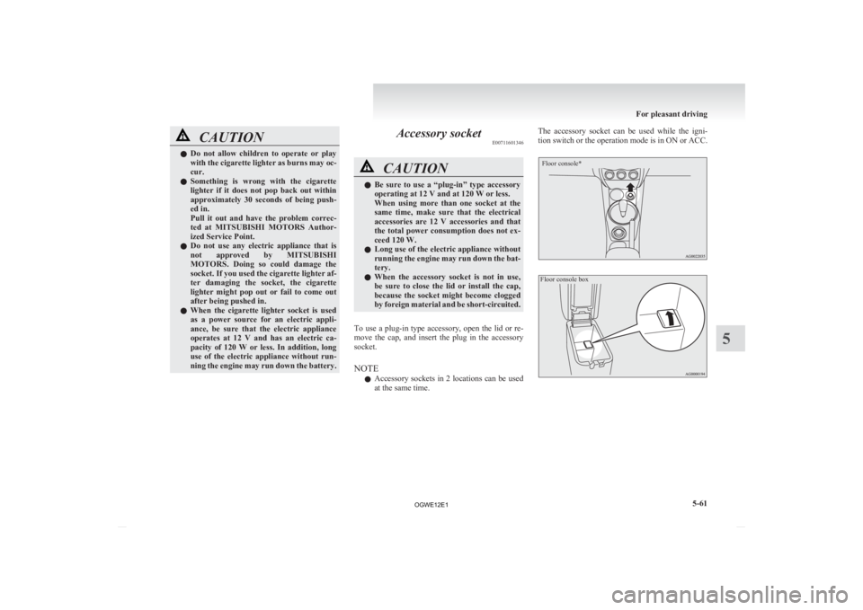
To use a plug-in type accessory, open the lid or re-
move
the cap, and insert the plug in the accessory
socket.
NOTE
l Accessory sockets in 2 locations can be used
at the same time. The accessory socket can be used while the igni-
tion
switch or the operation mode is in ON or ACC.
Floor console*
Floor console box For pleasant driving
5-61 5
OGWE12E1
Page 274 of 378
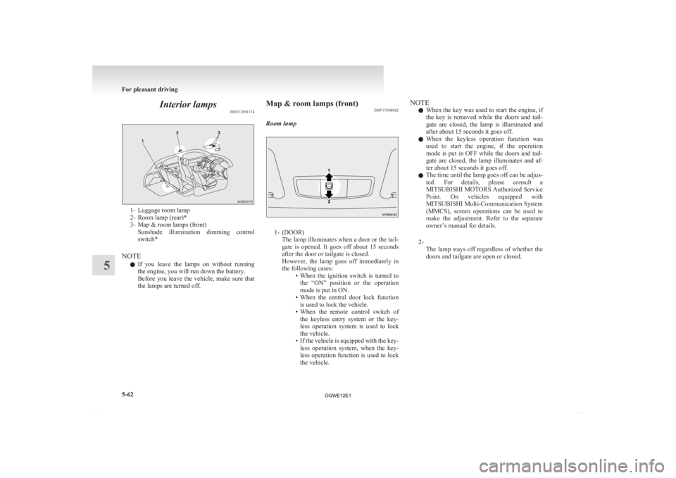
Interior lamps
E007120011741- Luggage room lamp
2-
Room lamp (rear)*
3- Map & room lamps (front) Sunshade illumination dimming control
switch*
NOTE l If you leave the lamps on without running
the engine, you will run down the battery.
Before you leave the vehicle, make sure that
the lamps are turned off. Map & room lamps (front)
E00717300582
Room lamp 1- (DOOR)
The
lamp illuminates when a door or the tail-
gate is opened. It goes off about 15 seconds
after the door or tailgate is closed.
However, the lamp goes off immediately in
the following cases: • When the ignition switch is turned tothe “ON” position or the operation
mode is put in ON.
• When the central door lock function is used to lock the vehicle.
• When the remote control switch of the keyless entry system or the key-
less operation system is used to lock
the vehicle.
• If the vehicle is equipped with the key- less operation system, when the key-
less operation function is used to lock
the vehicle. NOTE
l When
the key was used to start the engine, if
the key is removed while the doors and tail-
gate are closed, the lamp is illuminated and
after about 15 seconds it goes off.
l When the keyless operation function was
used to start the engine, if the operation
mode is put in OFF while the doors and tail-
gate are closed, the lamp illuminates and af-
ter about 15 seconds it goes off.
l The time until the lamp goes off can be adjus-
ted. For details, please consult a
MITSUBISHI MOTORS Authorized Service
Point. On vehicles equipped with
MITSUBISHI Multi-Communication System
(MMCS), screen operations can be used to
make the adjustment. Refer to the separate
owner’s manual for details.
2- The lamp stays off regardless of whether the
doors and tailgate are open or closed. For pleasant driving
5-62
5
OGWE12E1
Page 275 of 378
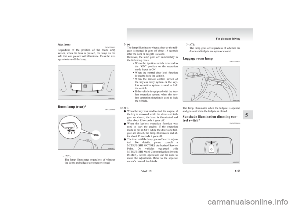
Map lamps
E00765200029
Regardless
of the position of the room lamp
switch, when the lens is pressed, the lamp on the
side that was pressed will illuminate. Press the lens
again to turn off the lamp. Room lamp (rear)*
E007123003691-
( )
The
lamp illuminates regardless of whether
the doors and tailgate are open or closed. 2- (•)
The
lamp illuminates when a door or the tail-
gate is opened. It goes off about 15 seconds
after the door or tailgate is closed.
However, the lamp goes off immediately in
the following cases: • When the ignition switch is turned tothe “ON” position or the operation
mode is put in ON.
• When the central door lock function is used to lock the vehicle.
• When the remote control switch of the keyless entry system or the key-
less operation system is used to lock
the vehicle.
• If the vehicle is equipped with the key- less operation system, when the key-
less operation function is used to lock
the vehicle.
NOTE l When the key was used to start the engine, if
the key is removed while the doors and tail-
gate are closed, the lamp is illuminated and
after about 15 seconds it goes off.
l When the keyless operation function was
used to start the engine, if the operation
mode is put in OFF while the doors and tail-
gate are closed, the lamp illuminates and af-
ter about 15 seconds it goes off.
l The time until the lamp goes off can be adjus-
ted. For details, please consult a
MITSUBISHI MOTORS Authorized Service
Point. On vehicles equipped with
MITSUBISHI Multi-Communication System
(MMCS), screen operations can be used to
make the adjustment. Refer to the separate
owner’s manual for details. 3-
( )
The lamp goes off regardless of whether the
doors and tailgate are open or closed.
Luggage room lamp E00712700624 The lamp illuminates when the tailgate is opened,
and goes out when the tailgate is closed.
Sunshade illumination dimming con-
trol switch*
E00765000030 For pleasant driving
5-63 5
OGWE12E1
Page 276 of 378
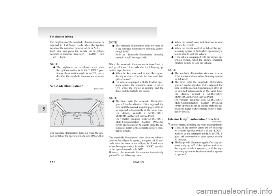
The brightness of the sunshade illumination can be
adjusted
to 3 different levels when the ignition
switch or the operation mode is in ON or ACC.
Each time you press the switch, the brightness
switches in sequence from high → middle → low
→ off → high.
NOTE
l The brightness can be adjusted even when
the ignition switch is in the “LOCK” posi-
tion or the operation mode is in OFF, provi-
ded that the sunshade illumination is turned
on.
Sunshade illumination* E00765100031The sunshade illumination turns on when the igni-
tion
switch or the operation mode is in ON or ACC. NOTE
l The
sunshade illumination does not turn on
if the sunshade illumination dimming control
switch is off.
Refer to “Sunshade illumination dimming
control switch” on page 5-63.
When the sunshade illumination is turned on, it
will go off about 15 seconds after the following op-
eration is performed. l When the key was used to start the engine,
the key is removed while the doors and tail-
gate are closed.
l For vehicles equipped with the keyless oper-
ation system, the operation mode is put in
OFF while the engine is running and the
doors and the tailgate are closed.
NOTE l The time until the sunshade illumination
goes off can be adjusted. If it is adjusted, the
time until the room & map lamps go off is al-
so adjusted automatically at the same time.
For details, consult a MITSUBISHI
MOTORS Authorized Service Point.
On vehicles equipped with MITSUBISHI
Multi-Communication System (MMCS),
screen operations can be used to make the ad-
justment. Refer to the separate owner’s man-
ual for details.
The sunshade illumination also turns on when a
door or the tailgate is opened, and goes off 15 sec-
onds after the door or the tailgate is closed, even
when the engine switch is in the “LOCK” position
or the operation mode is in OFF.
However, the sunshade illumination immediately
goes off in the following cases: l
When the central door lock function is used
to lock the vehicle.
l When the remote control switch of the key-
less entry system or the keyless operation sys-
tem is used to lock the vehicle.
l If the vehicle is equipped with the keyless op-
eration system, when the keyless operation
function is used to lock the vehicle.
NOTE l The sunshade illumination does not turn on
if the sunshade illumination dimming control
switch is off.
l The time until the sunshade illumination
goes off can be adjusted. If it is adjusted, the
time until the room & map lamps go off is al-
so adjusted automatically at the same time.
For details, consult a MITSUBISHI
MOTORS Authorized Service Point.
On vehicles equipped with MITSUBISHI
Multi-Communication System (MMCS),
screen operations can be used to make the ad-
justment. Refer to the separate owner’s man-
ual for details.
Interior lamp *1
auto-cutout function
E00712901216
*1
Interior lamps, including the room and map lamps
l If any of the interior lamps are left switched
on with the ignition switch is in the “LOCK”
position or the operation mode is in OFF, it
goes off automatically after approximately
30 minutes.
l The lamps will illuminate again after they au-
tomatically go off if the ignition switch or
the engine switch is operated, or if the key-
less entry system or keyless operation system
is operated. For pleasant driving
5-64
5
OGWE12E1
Page 284 of 378
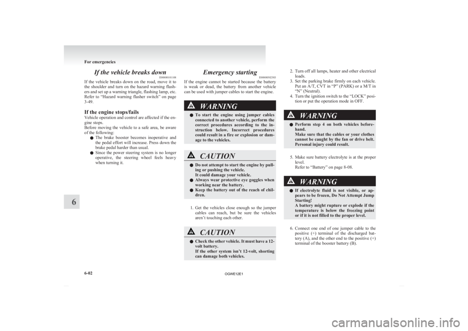
If the vehicle breaks down
E00800101108
If
the vehicle breaks down on the road, move it to
the shoulder and turn on the hazard warning flash-
ers and set up a warning triangle, flashing lamp, etc.
Refer to “Hazard warning flasher switch” on page
3-49.
If the engine stops/fails
Vehicle operation and control are affected if the en-
gine stops.
Before moving the vehicle to a safe area, be aware
of the following:
l The brake booster becomes inoperative and
the pedal effort will increase. Press down the
brake pedal harder than usual.
l Since the power steering system is no longer
operative, the steering wheel feels heavy
when turning it. Emergency starting
E00800502503
If
the engine cannot be started because the battery
is weak or dead, the battery from another vehicle
can be used with jumper cables to start the engine. WARNING
l To
start the engine using jumper cables
connected to another vehicle, perform the
correct procedures according to the in-
struction below. Incorrect procedures
could result in a fire or explosion or dam-
age to the vehicles. CAUTION
l
Do
not attempt to start the engine by pull-
ing or pushing the vehicle.
It could damage your vehicle.
l Always wear protective eye goggles when
working near the battery.
l Keep the battery out of the reach of chil-
dren.
1. Get
the vehicles close enough so the jumper cables can reach, but be sure the vehicles
aren’t touching each other. CAUTION
l
Check
the other vehicle. It must have a 12-
volt battery.
If the other system isn’t 12-volt, shorting
can damage both vehicles. 2. Turn
off all lamps, heater and other electrical
loads.
3. Set the parking brake firmly on each vehicle. Put an A/T, CVT in “P” (PARK) or a M/T in
“N” (Neutral).
4. Turn the ignition switch to the “LOCK” posi- tion or put the operation mode in OFF. WARNING
l Perform
step 4 on both vehicles before-
hand.
Make sure that the cables or your clothes
cannot be caught by the fan or drive belt.
Personal injury could result.
5. Make
sure battery electrolyte is at the proper level.
Refer to “Battery” on page 8-08. WARNING
l If
electrolyte fluid is not visible, or ap-
pears to be frozen, Do Not Attempt Jump
Starting!
A battery might rupture or explode if the
temperature is below the freezing point
or if it is not filled to the proper level.
6. Connect
one end of one jumper cable to the positive (+) terminal of the discharged bat-
tery (A), and the other end to the positive (+)
terminal of the booster battery (B).
For emergencies
6-02
6
OGWE12E1
Page 301 of 378
The regulations concerning towing may differ from
country
to country. It is recommended that you
obey the regulations of the area where you are driv-
ing your vehicle.
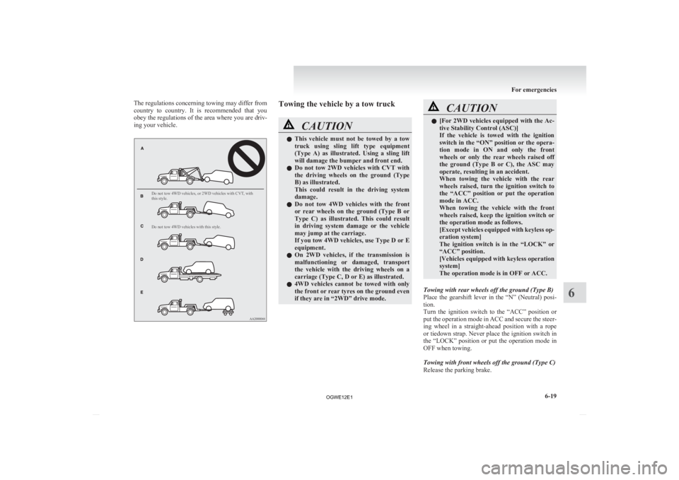
Do not tow 4WD vehicles, or 2WD vehicles with CVT, with
this style.
Do not tow 4WD vehicles with this style. Towing the vehicle by a tow truck
CAUTION
l
This
vehicle must not be towed by a tow
truck using sling lift type equipment
(Type A) as illustrated. Using a sling lift
will damage the bumper and front end.
l Do not tow 2WD vehicles with CVT with
the driving wheels on the ground (Type
B) as illustrated.
This could result in the driving system
damage.
l Do not tow 4WD vehicles with the front
or rear wheels on the ground (Type B or
Type C) as illustrated. This could result
in driving system damage or the vehicle
may jump at the carriage.
If you tow 4WD vehicles, use Type D or E
equipment.
l On 2WD vehicles, if the transmission is
malfunctioning or damaged, transport
the vehicle with the driving wheels on a
carriage (Type C, D or E) as illustrated.
l 4WD vehicles cannot be towed with only
the front or rear tyres on the ground even
if they are in “2WD” drive mode. CAUTION
l
[For
2WD vehicles equipped with the Ac-
tive Stability Control (ASC)]
If the vehicle is towed with the ignition
switch in the “ON” position or the opera-
tion mode in ON and only the front
wheels or only the rear wheels raised off
the ground (Type B or C), the ASC may
operate, resulting in an accident.
When towing the vehicle with the rear
wheels raised, turn the ignition switch to
the “ACC” position or put the operation
mode in ACC.
When towing the vehicle with the front
wheels raised, keep the ignition switch or
the operation mode as follows.
[Except vehicles equipped with keyless op-
eration system]
The ignition switch is in the “LOCK” or
“ACC” position.
[Vehicles equipped with keyless operation
system]
The operation mode is in OFF or ACC.
Towing with rear wheels off the ground (Type B)
Place
the gearshift lever in the “N” (Neutral) posi-
tion.
Turn the ignition switch to the “ACC” position or
put the operation mode in ACC and secure the steer-
ing wheel in a straight-ahead position with a rope
or tiedown strap. Never place the ignition switch in
the “LOCK” position or put the operation mode in
OFF when towing.
Towing with front wheels off the ground (Type C)
Release the parking brake. For emergencies
6-19 6
OGWE12E1
Page 302 of 378
Place the gearshift lever in the “N” (Neutral) posi-
tion
(M/T) or the selector lever in the “N” (NEU-
TRAL) position (CVT).
Emergency towing
If towing service is not available in an emergency,
your vehicle may be temporarily towed by a rope
secured to the towing hook.
If your vehicle is to be towed by another vehicle or
if your vehicle tows another vehicle, pay careful at-
tention to the following points:
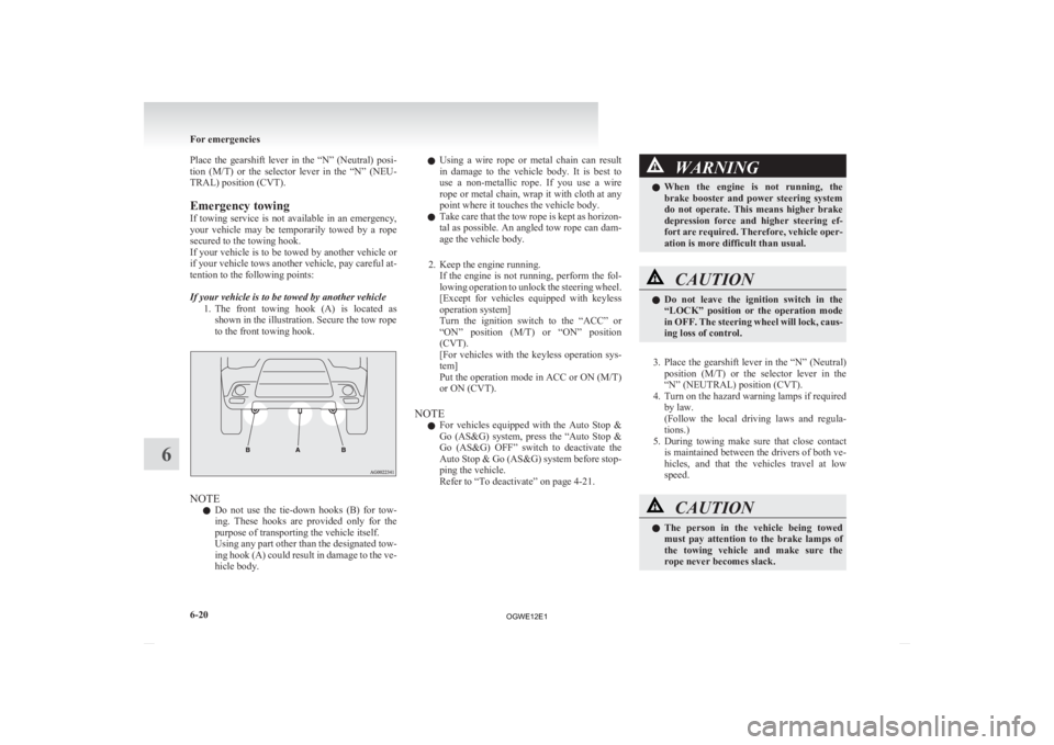
If your vehicle is to be towed by another vehicle
1. The front towing hook (A) is located asshown in the illustration. Secure the tow rope
to the front towing hook. NOTE
l Do
not use the tie-down hooks (B) for tow-
ing. These hooks are provided only for the
purpose of transporting the vehicle itself.
Using any part other than the designated tow-
ing hook (A) could result in damage to the ve-
hicle body. l
Using
a wire rope or metal chain can result
in damage to the vehicle body. It is best to
use a non-metallic rope. If you use a wire
rope or metal chain, wrap it with cloth at any
point where it touches the vehicle body.
l Take care that the tow rope is kept as horizon-
tal as possible. An angled tow rope can dam-
age the vehicle body.
2. Keep the engine running. If the engine is not running, perform the fol-
lowing operation to unlock the steering wheel.
[Except for vehicles equipped with keyless
operation system]
Turn the ignition switch to the “ACC” or
“ON” position (M/T) or “ON” position
(CVT).
[For vehicles with the keyless operation sys-
tem]
Put the operation mode in ACC or ON (M/T)
or ON (CVT).
NOTE l For vehicles equipped with the Auto Stop &
Go (AS&G) system, press the “Auto Stop &
Go (AS&G) OFF” switch to deactivate the
Auto Stop & Go (AS&G) system before stop-
ping the vehicle.
Refer to “To deactivate” on page 4-21. WARNING
l When
the engine is not running, the
brake booster and power steering system
do not operate. This means higher brake
depression force and higher steering ef-
fort are required. Therefore, vehicle oper-
ation is more difficult than usual. CAUTION
l
Do
not leave the ignition switch in the
“LOCK” position or the operation mode
in OFF. The steering wheel will lock, caus-
ing loss of control.
3. Place
the gearshift lever in the “N” (Neutral) position (M/T) or the selector lever in the
“N” (NEUTRAL) position (CVT).
4. Turn on the hazard warning lamps if required by law.
(Follow the local driving laws and regula-
tions.)
5. During towing make sure that close contact is maintained between the drivers of both ve-
hicles, and that the vehicles travel at low
speed. CAUTION
l
The
person in the vehicle being towed
must pay attention to the brake lamps of
the towing vehicle and make sure the
rope never becomes slack. For emergencies
6-20
6
OGWE12E1
Page 312 of 378
Service precautions
E01000100878
Adequate
care of your vehicle at regular intervals
serves to preserve the value and appearance as long
as possible.
Maintenance items as described in this owner’s man-
ual can be performed by the owner.
We recommend you to have the periodic inspection
and maintenance performed by a MITSUBISHI
MOTORS Authorized Service Point or another spe-
cialist.
In the event a malfunction or a problem is discov-
ered, we recommend you to have it checked and re-
paired. This section contains information on inspec-
tion maintenance procedures that you can do your-
self. Follow the instructions and cautions for each
of the various procedures. WARNING
l When
checking or servicing the inside of
the engine compartment, make sure the
engine is switched off and has had a
chance to cool down.
l If it is necessary to do work in the engine
compartment with the engine running, be
especially careful that your clothing, hair,
etc., does not become caught by the fan,
drive belts, or other moving parts.
l The fan may turn on automatically even
if the engine is not running. Turn the igni-
tion switch to the “LOCK” position or
put the operation mode in OFF to be safe
while you work in the engine compart-
ment. WARNING
l Do
not smoke, cause sparks or allow open
flames around fuel or battery. The fumes
are flammable.
l Be extremely cautious when working
around the battery. It contains poisonous
and corrosive sulphuric acid.
l Do not get under your vehicle with just
the body jack supporting it. Always use
automotive jack stands.
l Improper handling of components and
materials used in the vehicle can endan-
ger your personal safety. We recommend
you to consult a specialist for necessary in-
formation. Catalytic converter
E01000200765
The
exhaust gas scavenging devices used with the
catalytic converter are extremely efficient for the re-
duction of noxious gases. The catalytic converter is
installed in the exhaust system.
It is important to keep the engine properly tuned to
ensure proper catalyst operation and prevent possi-
ble catalyst damage. WARNING
l As
with any vehicle, do not park or oper-
ate this vehicle in areas where combusti-
ble materials such as dry grass or leaves
can come in contact with a hot exhaust
since a fire could occur.
l Paint should not be applied to the catalyt-
ic converter.
NOTE l Use
fuel of the type recommended in “Fuel
selection” on page 02. Maintenance
8-02
8
OGWE12E1
Page 314 of 378
NOTE
l If
this does not close the bonnet, release it
from a slightly higher position.
l Do not press down the bonnet hard with a
hand as it may damage the bonnet.
l For vehicles equipped with the security
alarm system, if you drive with the bonnet
left open, warning display is displayed on the
information screen in the multi-information
display.
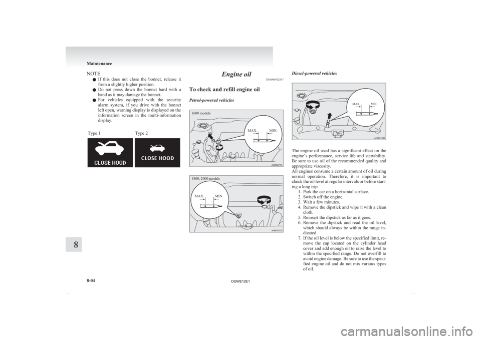
Type 1 Type 2 Engine oil
E01000402817
To check and refill engine oil
Petrol-powered vehicles
1600 models
MAX. MIN.
1800, 2000 models
MAX. MIN. Diesel-powered vehicles
MAX. MIN.
The engine oil used has a significant effect on the
engine’s
performance, service life and startability.
Be sure to use oil of the recommended quality and
appropriate viscosity.
All engines consume a certain amount of oil during
normal operation. Therefore, it is important to
check the oil level at regular intervals or before start-
ing a long trip. 1. Park the car on a horizontal surface.
2. Switch off the engine.
3. Wait a few minutes.
4. Remove the dipstick and wipe it with a cleancloth.
5. Reinsert the dipstick as far as it goes.
6. Remove the dipstick and read the oil level, which should always be within the range in-
dicated.
7. If the oil level is below the specified limit, re- move the cap located on the cylinder head
cover and add enough oil to raise the level to
within the specified range. Do not overfill to
avoid engine damage. Be sure to use the speci-
fied engine oil and do not mix various types
of oil. Maintenance
8-04
8
OGWE12E1
Page 318 of 378
Fluid type
Use
brake fluid conforming to DOT3 or DOT4
from a sealed container. The brake fluid is hygro-
scopic. Too much moisture in the brake fluid will
adversely affect the brake system, reducing the per-
formance. CAUTION
l
Take
care in handling brake fluid as it is
harmful to the eyes, may irritate your
skin and also damage painted surfaces.
l Use only the specified brake fluid.
Do not mix or add different brands of
brake fluid to prevent chemical reactions.
Do not let any petroleum-based fluid
touch, mix with, or get into the brake fluid.
This will damage the seals.
l Keep the reservoir tank cap closed to pre-
vent the brake fluid from deteriorating ex-
cept maintenance.
l Clean the filler cap before removing and
close the cap securely after maintenance. Battery
E01001202131
The
condition of the battery is very important for
quick starting and to keep the vehicle’s electrical
system working properly. Regular inspection and
care are especially important in cold weather.
NOTE
l After replacing the battery, the electronic con-
trol system data for the automatic transmis-
sion, etc., will be erased. As a result, shift
shocks may occur.
Shift shocks will become smoother after sev-
eral changes in speed.
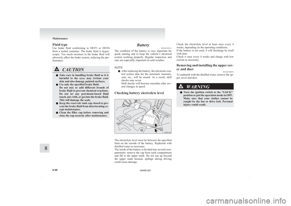
Checking battery electrolyte level The electrolyte level must be between the specified
limit
on the outside of the battery. Replenish with
distilled water as necessary.
The inside of the battery is divided into several com-
partments; remove the cap from each compartment
and fill to the upper mark. Do not top up beyond
the upper mark because spillage during driving
could cause damage. Check the electrolyte level at least once every 4
weeks, depending on the operating conditions.
If
the battery is not used, it will discharge by itself
with time.
Check it once every 4 weeks and charge with low
current as necessary.
Removing and installing the upper cov-
er and duct E01010700079
To replenish with the distilled water, remove the up-
per cover and duct. WARNING
l Turn
the ignition switch to the “LOCK”
position or put the operation mode in OFF.
Make sure that your clothes cannot be
caught by the fan or drive belt. Personal
injury could result. Maintenance
8-08
8
OGWE12E1