ECU MITSUBISHI ASX 2012 (in English) Owner's Guide
[x] Cancel search | Manufacturer: MITSUBISHI, Model Year: 2012, Model line: ASX, Model: MITSUBISHI ASX 2012Pages: 378, PDF Size: 18.2 MB
Page 301 of 378
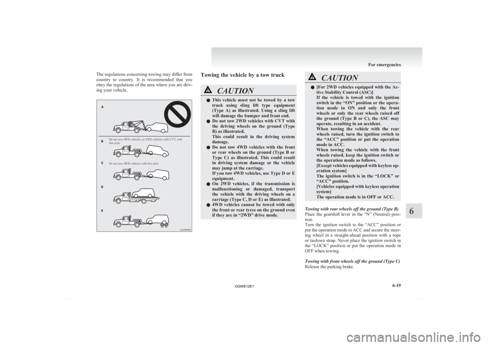
The regulations concerning towing may differ from
country
to country. It is recommended that you
obey the regulations of the area where you are driv-
ing your vehicle.
Do not tow 4WD vehicles, or 2WD vehicles with CVT, with
this style.
Do not tow 4WD vehicles with this style. Towing the vehicle by a tow truck
CAUTION
l
This
vehicle must not be towed by a tow
truck using sling lift type equipment
(Type A) as illustrated. Using a sling lift
will damage the bumper and front end.
l Do not tow 2WD vehicles with CVT with
the driving wheels on the ground (Type
B) as illustrated.
This could result in the driving system
damage.
l Do not tow 4WD vehicles with the front
or rear wheels on the ground (Type B or
Type C) as illustrated. This could result
in driving system damage or the vehicle
may jump at the carriage.
If you tow 4WD vehicles, use Type D or E
equipment.
l On 2WD vehicles, if the transmission is
malfunctioning or damaged, transport
the vehicle with the driving wheels on a
carriage (Type C, D or E) as illustrated.
l 4WD vehicles cannot be towed with only
the front or rear tyres on the ground even
if they are in “2WD” drive mode. CAUTION
l
[For
2WD vehicles equipped with the Ac-
tive Stability Control (ASC)]
If the vehicle is towed with the ignition
switch in the “ON” position or the opera-
tion mode in ON and only the front
wheels or only the rear wheels raised off
the ground (Type B or C), the ASC may
operate, resulting in an accident.
When towing the vehicle with the rear
wheels raised, turn the ignition switch to
the “ACC” position or put the operation
mode in ACC.
When towing the vehicle with the front
wheels raised, keep the ignition switch or
the operation mode as follows.
[Except vehicles equipped with keyless op-
eration system]
The ignition switch is in the “LOCK” or
“ACC” position.
[Vehicles equipped with keyless operation
system]
The operation mode is in OFF or ACC.
Towing with rear wheels off the ground (Type B)
Place
the gearshift lever in the “N” (Neutral) posi-
tion.
Turn the ignition switch to the “ACC” position or
put the operation mode in ACC and secure the steer-
ing wheel in a straight-ahead position with a rope
or tiedown strap. Never place the ignition switch in
the “LOCK” position or put the operation mode in
OFF when towing.
Towing with front wheels off the ground (Type C)
Release the parking brake. For emergencies
6-19 6
OGWE12E1
Page 302 of 378
Place the gearshift lever in the “N” (Neutral) posi-
tion
(M/T) or the selector lever in the “N” (NEU-
TRAL) position (CVT).
Emergency towing
If towing service is not available in an emergency,
your vehicle may be temporarily towed by a rope
secured to the towing hook.
If your vehicle is to be towed by another vehicle or
if your vehicle tows another vehicle, pay careful at-
tention to the following points:
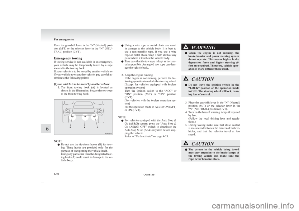
If your vehicle is to be towed by another vehicle
1. The front towing hook (A) is located asshown in the illustration. Secure the tow rope
to the front towing hook. NOTE
l Do
not use the tie-down hooks (B) for tow-
ing. These hooks are provided only for the
purpose of transporting the vehicle itself.
Using any part other than the designated tow-
ing hook (A) could result in damage to the ve-
hicle body. l
Using
a wire rope or metal chain can result
in damage to the vehicle body. It is best to
use a non-metallic rope. If you use a wire
rope or metal chain, wrap it with cloth at any
point where it touches the vehicle body.
l Take care that the tow rope is kept as horizon-
tal as possible. An angled tow rope can dam-
age the vehicle body.
2. Keep the engine running. If the engine is not running, perform the fol-
lowing operation to unlock the steering wheel.
[Except for vehicles equipped with keyless
operation system]
Turn the ignition switch to the “ACC” or
“ON” position (M/T) or “ON” position
(CVT).
[For vehicles with the keyless operation sys-
tem]
Put the operation mode in ACC or ON (M/T)
or ON (CVT).
NOTE l For vehicles equipped with the Auto Stop &
Go (AS&G) system, press the “Auto Stop &
Go (AS&G) OFF” switch to deactivate the
Auto Stop & Go (AS&G) system before stop-
ping the vehicle.
Refer to “To deactivate” on page 4-21. WARNING
l When
the engine is not running, the
brake booster and power steering system
do not operate. This means higher brake
depression force and higher steering ef-
fort are required. Therefore, vehicle oper-
ation is more difficult than usual. CAUTION
l
Do
not leave the ignition switch in the
“LOCK” position or the operation mode
in OFF. The steering wheel will lock, caus-
ing loss of control.
3. Place
the gearshift lever in the “N” (Neutral) position (M/T) or the selector lever in the
“N” (NEUTRAL) position (CVT).
4. Turn on the hazard warning lamps if required by law.
(Follow the local driving laws and regula-
tions.)
5. During towing make sure that close contact is maintained between the drivers of both ve-
hicles, and that the vehicles travel at low
speed. CAUTION
l
The
person in the vehicle being towed
must pay attention to the brake lamps of
the towing vehicle and make sure the
rope never becomes slack. For emergencies
6-20
6
OGWE12E1
Page 308 of 378
CAUTION
• When washing around the door glass,
hold the nozzle at a distance of more
than 70 cm and at right angles to the
glass surface.
l After washing the vehicle, drive the vehi-
cle slowly while lightly depressing the
brake pedal several times in order to dry
out the brakes.
Leaving the brakes wet could result in re-
duced braking performance. Also, there
is a possibility that they could freeze up
or become inoperative due to rust, render-
ing the vehicle unable to move.
l When using an automatic car wash, pay
attention to the following items, referring
to the operation manual or consulting a
car wash operator. If the following proce-
dure is not followed, it could result in dam-
age to your vehicle.
• The outside mirrors are retracted.
• The antenna is removed.
• The wiper arms are secured in placewith tape.
• If your vehicle is equipped with a rear spoiler or roof rails, consult a car
wash operator before using the car
wash.
• If your vehicle has rain sensor wipers, place the wiper switch lever in the
“OFF” position to deactivate the rain
sensor. During cold weather
Salt
and other chemicals spread on the roads in
some areas in winter can have a harmful effect on
the vehicle body. You should therefore wash the ve-
hicle as often as possible in accordance with our
care-instructions. It is recommended to have a pres-
ervative applied and the underfloor protection
checked before and after the cold weather season.
After washing your vehicle, wipe off all water-
drops from the rubber parts around the doors to pre-
vent the doors from freezing.
NOTE
l To prevent freezing of the weatherstripping
on the doors, bonnet, etc., they should be trea-
ted with silicone spray.
Waxing E00901000863
Waxing the vehicle will help prevent the adherence
of
dust and road chemicals to the paintwork. Apply
a wax solution after washing the vehicle, or at least
once every three months to assist displacing of water.
Do not wax your vehicle in direct sunlight. You
should wax after the surfaces have cooled. CAUTION
l
Waxes
containing high abrasive com-
pounds should not be used. Such waxes re-
move rust and stains effectively from the
paintwork but they are harmful to the lus-
tre on the painted surface and the plated
surface.
Further, they are harmful to glossy surfa-
ces such as grille, garnish, mouldings, etc. CAUTION
l
Do
not use petrol or paint thinners to re-
move road tar or other contamination to
the painted surface.
l Do not apply wax to sections that have a
black mat paint coating, as doing so
could cause uneven discolouration, spots
or stains. If wax gets on such areas, wipe
it off using lukewarm water and a soft
cloth.
Polishing E00901100066
The vehicle should only be polished if the paint-
work
has become stained or lost its lustre. Do not
polish parts with a mat coating and the plastic bump-
ers. Doing so could cause stains or damage the finish.
Damaged paint E00901200054
Small cracks and scratches in the paint coat should
be
touched up as soon as possible with
MITSUBISHI touch-up paint to prevent corrosion.
Check body areas facing the road or the tyres care-
fully for damage to the paint caused by gravels,
etc. The paint code number for your vehicle can be
found on the vehicle information code plate in the
engine compartment.
Cleaning plastic parts E00901300707
Use a sponge or chamois leather.
If
a car wax adheres on a grey or black rough sur-
face of the bumper, moulding or lamps, the surface
becomes white. In such a case, wipe it off using
lukewarm water and soft cloth or chamois leather. Vehicle care
7-04
7
OGWE12E1
Page 313 of 378

Bonnet
E01000302698
To open 1. Pull
the release lever towards you to unlock
the bonnet. 2. Raise
the bonnet while pressing the safety
lock. NOTE
l Only
open the bonnet when the wipers are in
the parked position. In any other position,
the wipers could damage the paint or bonnet.
3. Support the bonnet by inserting the support bar in its slot. CAUTION
l
Note
that the support bar may disengage
the bonnet if the open bonnet is lifted by
a strong wind. CAUTION
l
After
inserting the support bar into the
slot, make sure the bar supports the bon-
net securely from falling down on to your
head or body.
To close 1. Unlatch
the support bar and clip it in its holder.
2. Slowly lower the bonnet to a position about 20 cm above the closed position, then let it
drop.
3. Make sure the bonnet is securely locked by softly lifting the centre of the bonnet. CAUTION
l
Be
careful that hands or fingers are not
trapped when closing the bonnet.
l Before driving, make sure that the bon-
net is securely locked. An incompletely
locked bonnet can suddenly open while
driving. This can be extremely dangerous. Maintenance
8-03 8LHD RHD
OGWE12E1
Page 314 of 378
NOTE
l If
this does not close the bonnet, release it
from a slightly higher position.
l Do not press down the bonnet hard with a
hand as it may damage the bonnet.
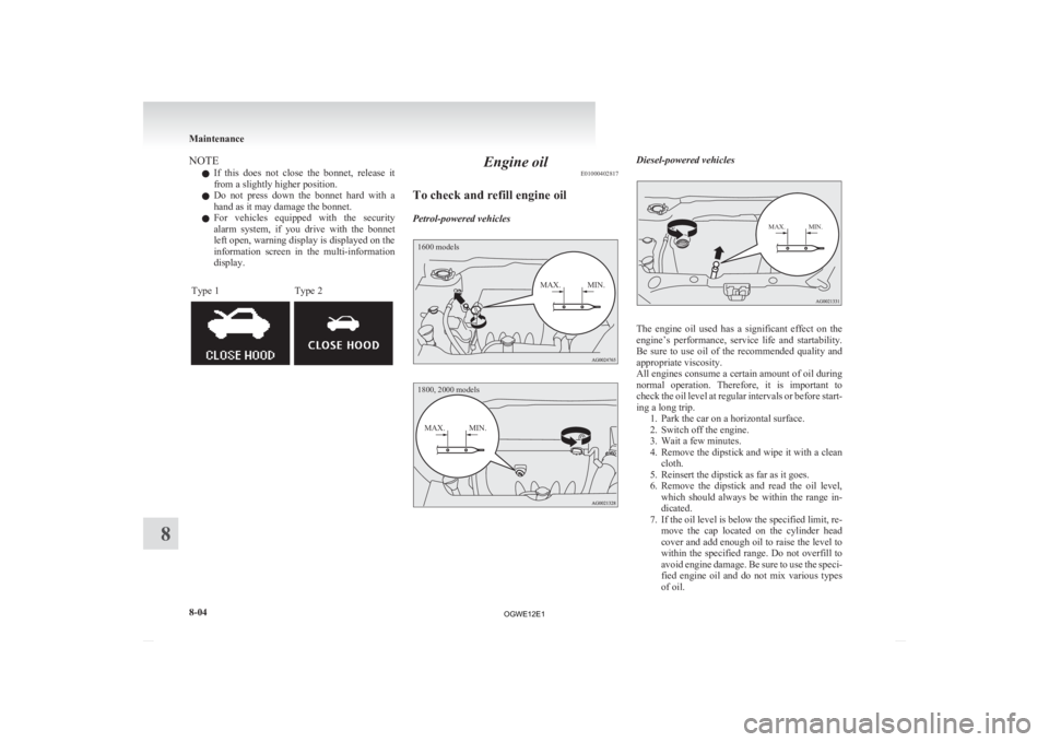
l For vehicles equipped with the security
alarm system, if you drive with the bonnet
left open, warning display is displayed on the
information screen in the multi-information
display.
Type 1 Type 2 Engine oil
E01000402817
To check and refill engine oil
Petrol-powered vehicles
1600 models
MAX. MIN.
1800, 2000 models
MAX. MIN. Diesel-powered vehicles
MAX. MIN.
The engine oil used has a significant effect on the
engine’s
performance, service life and startability.
Be sure to use oil of the recommended quality and
appropriate viscosity.
All engines consume a certain amount of oil during
normal operation. Therefore, it is important to
check the oil level at regular intervals or before start-
ing a long trip. 1. Park the car on a horizontal surface.
2. Switch off the engine.
3. Wait a few minutes.
4. Remove the dipstick and wipe it with a cleancloth.
5. Reinsert the dipstick as far as it goes.
6. Remove the dipstick and read the oil level, which should always be within the range in-
dicated.
7. If the oil level is below the specified limit, re- move the cap located on the cylinder head
cover and add enough oil to raise the level to
within the specified range. Do not overfill to
avoid engine damage. Be sure to use the speci-
fied engine oil and do not mix various types
of oil. Maintenance
8-04
8
OGWE12E1
Page 315 of 378

8. After adding oil, close the cap securely.
9.
Confirm the oil level by repeating step 4 to 6. CAUTION
l
In
diesel-powered vehicles, when burning
away and removing soot accumulated in
the DPF, fuel can mix with the engine oil
and an increase in the engine oil level
may occur. This does not indicate an ab-
normality.
However, if the engine oil level is at or
over the “X” mark (B) on the engine oil
dipstick (A), change the engine oil. NOTE
l The
engine oil will deteriorate rapidly if the
vehicle is subjected to severe conditions, re-
quiring earlier oil replacement.
Please refer to the maintenance schedule.
l For information on how to dispose of used en-
gine oil, refer to page 05. Recommended engine oil viscosity
Petrol-powered vehicles
l
Select
engine oil of the proper SAE viscosity
number according to the atmospheric temper-
ature.
SAE 0W-20, 0W-30, 5W-30 and 5W-40 en-
gine oils can only be used if they meet
ACEA A3/B3, A3/B4 or A5/B5 and API SM
(or higher) specifications.
l Use engine oil conforming to the following
classification:
• API classification: “For service SM” (orhigher)
• ILSAC certificated oil
• ACEA classification: “For service A1/B1, A3/B3, A3/B4 or
A5/B5” NOTE
l Use
of additives is not recommended since
they may reduce the effectiveness of addi-
tives already included in the engine oil. It
may result in failure of the mechanical assem-
bly.
Diesel-powered vehicles l
Select
engine oil of the proper SAE viscosity
number according to the atmospheric temper-
ature.
l Use engine oil conforming to the following
classification:
• ACEA classification:“For service C1, C2, C3 or C4”
• JASO classification: “For service DL-1”
If those classifications are not available,
contact a MITSUBISHI MOTORS Au-
thorized Service Point. Maintenance
8-05 8
OGWE12E1
Page 318 of 378
Fluid type
Use
brake fluid conforming to DOT3 or DOT4
from a sealed container. The brake fluid is hygro-
scopic. Too much moisture in the brake fluid will
adversely affect the brake system, reducing the per-
formance. CAUTION
l
Take
care in handling brake fluid as it is
harmful to the eyes, may irritate your
skin and also damage painted surfaces.
l Use only the specified brake fluid.
Do not mix or add different brands of
brake fluid to prevent chemical reactions.
Do not let any petroleum-based fluid
touch, mix with, or get into the brake fluid.
This will damage the seals.
l Keep the reservoir tank cap closed to pre-
vent the brake fluid from deteriorating ex-
cept maintenance.
l Clean the filler cap before removing and
close the cap securely after maintenance. Battery
E01001202131
The
condition of the battery is very important for
quick starting and to keep the vehicle’s electrical
system working properly. Regular inspection and
care are especially important in cold weather.
NOTE
l After replacing the battery, the electronic con-
trol system data for the automatic transmis-
sion, etc., will be erased. As a result, shift
shocks may occur.
Shift shocks will become smoother after sev-
eral changes in speed.
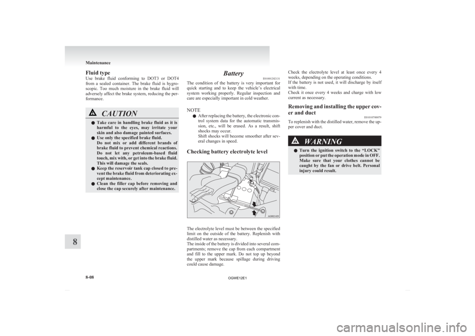
Checking battery electrolyte level The electrolyte level must be between the specified
limit
on the outside of the battery. Replenish with
distilled water as necessary.
The inside of the battery is divided into several com-
partments; remove the cap from each compartment
and fill to the upper mark. Do not top up beyond
the upper mark because spillage during driving
could cause damage. Check the electrolyte level at least once every 4
weeks, depending on the operating conditions.
If
the battery is not used, it will discharge by itself
with time.
Check it once every 4 weeks and charge with low
current as necessary.
Removing and installing the upper cov-
er and duct E01010700079
To replenish with the distilled water, remove the up-
per cover and duct. WARNING
l Turn
the ignition switch to the “LOCK”
position or put the operation mode in OFF.
Make sure that your clothes cannot be
caught by the fan or drive belt. Personal
injury could result. Maintenance
8-08
8
OGWE12E1
Page 320 of 378

We recommend you to have the battery checked be-
fore
the start of cold weather and, if necessary,
have it charged or replaced.
This does not only ensure reliable starting, but a bat-
tery which is kept fully charged also has a longer life.
Disconnection and connection E01011000079
To disconnect the battery cable, stop the engine,
first
disconnect the negative (-) terminal and then
the positive (+) terminal.
When connecting the battery, first connect the posi-
tive (+) terminal and then the negative (-) terminal.
NOTE
l Open the terminal cover (A) before discon-
necting or connecting the positive (+) termi-
nal of the battery.
l Loosen the nut (B), and then disconnect the
battery cable from the positive (+) terminal.
Petrol-powered vehicles
Diesel-powered vehicles WARNING
l Keep
sparks, cigarettes, and flames away
from the battery because the battery
could explode.
l The battery electrolyte is extremely caus-
tic. Do not allow it to come in contact
with your eyes, skin, clothing, or the pain-
ted surfaces of the vehicle.
Spilt electrolyte should be flushed imme-
diately with ample amounts of water.
Irritation to eyes or skin from contact
with electrolyte requires immediate medi-
cal attention.
l Ventilate when charging or using the bat-
tery in an enclosed space. CAUTION
l
Keep it out of reach of children.
l Never
disconnect the battery with the ig-
nition switch or the operation mode in
ON. Doing so could damage electric com-
ponents. CAUTION
l
Never
short-circuit the battery. This
could cause it to overheat and be damaged.
l If the battery is to be quick-charged, first
disconnect the battery cables.
l In order to prevent a short circuit, be
sure to disconnect the negative (-) termi-
nal first.
l Always wear protective eye goggles when
working near the battery.
l Do not bring the nearby parts, the plastic
parts and so on into contact with sulphu-
ric acid (battery electrolyte) which may
crack, stain or discolour them.
If they are in contact, wipe off with soft
cloth, chamois or the like and an aqueous
solution of neutral detergent then imme-
diately rinse the affected parts with plen-
ty of water.
NOTE l Keep
the terminals clean. After the battery is
connected, apply terminal protection grease.
To clean the terminals, use lukewarm water.
l Check to see if the battery is securely instal-
led and cannot be moved during travel. Also
check each terminal for tightness.
l When the vehicle is to be left unused for a
long period of time, remove the battery and
store it in a place where the battery fluid will
not freeze. The battery should be stored only
in a fully charged condition. Maintenance
8-10
8
OGWE12E1
Page 326 of 378

Refer to the illustration to ensure that the re-
tainers
are correctly aligned as you attach
them. 4. Insert
the wiper blade into the arm, starting
with the opposite end of the blade from the
stopper. Make sure the hook (B) is fitted cor-
rectly in the grooves in the blade.
NOTE l If a retainer is not supplied with the new wip-
er blade, use the retainer from the old blade. 5. Push
the wiper blade until the hook (B) en-
gages securely with the stopper (A). Rear window wiper blades
1.
Lift the wiper arm off the window glass.
2. Pull the wiper blade downward to disengage it from the stopper (A) at the end of the wip-
er arm. Pull the wiper blade further to re-
move it.
3. Slide a new wiper blade through the hook (B) on the wiper arm. NOTE
l Do
not allow the wiper arm to fall onto the
window glass; it could damage the glass.
4. Firmly insert the retainer (C) into the groove (D) in the wiper blade.
Refer to the illustration to ensure that the re-
tainers are correctly aligned as you insert
them into the groove. NOTE
l If
a retainer is not supplied with the new wip-
er blade, use the retainer from the old blade. Maintenance
8-16
8
OGWE12E1
Page 332 of 378

No. Symbol Electrical system Capaci-
ties
5 Alternator 7.5 A
6 Headlamp washer 20 A
7 Air conditioning 10 A
8 ETV/Oil cooler fan
(Twin Clutch SST) 15 A
9 Security horn 20 A
10 Wiper de-icer 15 A
11 — ——
12 Electric tailgate 30 A
13 Daytime running
lamps 10 A
14 Headlamp high-
beam (left) 10 A
15 Headlamp high-
beam (right) 10 A
16 Head-
lamp low
beam (left) Dis-
charge 20 A
17 Head-
lamp low
beam
(right) Dis-
charge 20 A
*1 : Fusible link No. Symbol Electrical system Capaci-
ties
18 Head-
lamp low
beam (left) Halogen 10 A
19 Head-
lamp low
beam
(right) Halogen 10 A
20 ENG/POWER 10 A
21 Ignition coil 10 A
22 ENG/POWER 20 A
Fuel line heater 25 A
23 Fuel pump 15 A
24 Starter
30 A*1
25 — ——
26 Anti-lock brake
system 40 A
*1
27 Anti-lock brake
system 30 A
*1
28 Air conditioning
condenser fan mo- tor 30 A
*1
29 Radiator fan motor
40 A*1
*1 : Fusible link No. Symbol Electrical system Capaci-
ties
30 IOD IOD 30 A
31 Audio system amp 30 A
32 Diesel 30 A
33 — Spare fuse 10 A
34 — Spare fuse 15 A
35 — Spare fuse 20 A
*1 : Fusible link l
Some fuses may not be installed on your ve-
hicle, depending on the vehicle model or spec-
ifications.
l The table above shows the main equipment
corresponding to each fuse.
The fuse box does not contain spare 7.5 A, 25 A or
30 A fuses. If one of these fuses burns out, substi-
tute with the following fuse.
7.5 A: 10 A spare fuse
25 A: 20 A spare fuse
30 A: 30 A audio system amp fuse
When using a substitute fuse, replace with a fuse of
the correct capacity as soon as possible. Maintenance
8-22
8
OGWE12E1