ESP MITSUBISHI ASX 2012 (in English) Owner's Guide
[x] Cancel search | Manufacturer: MITSUBISHI, Model Year: 2012, Model line: ASX, Model: MITSUBISHI ASX 2012Pages: 378, PDF Size: 18.2 MB
Page 307 of 378
NOTE
l If
genuine leather is wet with water or is wash-
ed in water, wipe off water as quickly as pos-
sible with a dry, soft cloth. If left damp, mil-
dew may grow.
l The genuine leather surface may be damaged
if a nylon brush or synthetic fibre is rubbed
hard against it.
l Organic solvents such as benzine, kerosene,
alcohol and petrol, acid or alkaline solvents
may discolour the genuine leather surface.
Be sure to use neutral detergents.
l Remove dirty patches or oil substances quick-
ly as they can stain genuine leather.
l The genuine leather surface may harden and
shrink if it is exposed to direct sun for long
hours. When your vehicle is parked, place it
in the shade as much as possible.
l When the temperature of the vehicle interior
rises in summer, vinyl products left on the
genuine leather seat may deteriorate and
stick to the seat. Cleaning the exterior of your
vehicle E00900700108
If
the following is left on your vehicle, it may
cause corrosion, discolouration and stains, wash
the vehicle as soon as possible.
l Seawater, road deicing products.
l Soot and dust, iron powder from factories,
chemical substance (acids, alkalis, coal-tar,
etc.).
l Droppings from birds, carcasses of insects,
tree sap, etc.
Washing E00900902276
Chemicals contained in the dirt and dust picked up
from
the road surface can damage the paint coat
and body of your vehicle if left in prolonged contact.
Frequent washing and waxing is the best way to pro-
tect your vehicle from this damage. This will also
be effective in protecting it from environmental el-
ements such as rain, snow, salt air, etc.
Do not wash the vehicle in direct sunlight. Park the
vehicle in the shade and spray it with water to re-
move dust. Next, using an ample amount of clean
water and a car washing brush or sponge, wash the
vehicle from top to bottom.
Use a mild car washing soap if necessary. Rinse
thoroughly and wipe dry with a soft cloth. After
washing the vehicle, carefully clean the joints and
flanges of the doors, bonnet and other sections
where dirt is likely to remain. CAUTION
l
When
washing the under side of your ve-
hicle or wheel, be careful not to injure
your hands.
l If your vehicle has rain sensor wipers,
place the wiper switch lever in the “OFF”
position to deactivate the rain sensor be-
fore washing the vehicle. Otherwise, the
wipers will operate in the presence of wa-
ter spray on the windscreen and may get
damaged as a result.
l Refrain from excessively using a car wash
as its brushes may scratch the paint sur-
face, causing it to lose its gloss. Scratches
will be especially visible on darker col-
oured vehicles.
l Never spray or splash water on the electri-
cal components in the engine compart-
ment. Doing so could have an adverse ef-
fect on the engine startability.
Exercise caution also when washing the
underbody; be careful not to spray water
into the engine compartment.
l Some types of hot water washing equip-
ment apply high pressure and heat to the
vehicle. They may cause heat distortion
and damage to the vehicle resin parts and
may result in flooding of the vehicle inte-
rior.
Therefore;
• Maintain a distance of approx. 70 cmor more between the vehicle body and
the washing nozzle. Vehicle care
7-03 7
OGWE12E1
Page 312 of 378
Service precautions
E01000100878
Adequate
care of your vehicle at regular intervals
serves to preserve the value and appearance as long
as possible.
Maintenance items as described in this owner’s man-
ual can be performed by the owner.
We recommend you to have the periodic inspection
and maintenance performed by a MITSUBISHI
MOTORS Authorized Service Point or another spe-
cialist.
In the event a malfunction or a problem is discov-
ered, we recommend you to have it checked and re-
paired. This section contains information on inspec-
tion maintenance procedures that you can do your-
self. Follow the instructions and cautions for each
of the various procedures. WARNING
l When
checking or servicing the inside of
the engine compartment, make sure the
engine is switched off and has had a
chance to cool down.
l If it is necessary to do work in the engine
compartment with the engine running, be
especially careful that your clothing, hair,
etc., does not become caught by the fan,
drive belts, or other moving parts.
l The fan may turn on automatically even
if the engine is not running. Turn the igni-
tion switch to the “LOCK” position or
put the operation mode in OFF to be safe
while you work in the engine compart-
ment. WARNING
l Do
not smoke, cause sparks or allow open
flames around fuel or battery. The fumes
are flammable.
l Be extremely cautious when working
around the battery. It contains poisonous
and corrosive sulphuric acid.
l Do not get under your vehicle with just
the body jack supporting it. Always use
automotive jack stands.
l Improper handling of components and
materials used in the vehicle can endan-
ger your personal safety. We recommend
you to consult a specialist for necessary in-
formation. Catalytic converter
E01000200765
The
exhaust gas scavenging devices used with the
catalytic converter are extremely efficient for the re-
duction of noxious gases. The catalytic converter is
installed in the exhaust system.
It is important to keep the engine properly tuned to
ensure proper catalyst operation and prevent possi-
ble catalyst damage. WARNING
l As
with any vehicle, do not park or oper-
ate this vehicle in areas where combusti-
ble materials such as dry grass or leaves
can come in contact with a hot exhaust
since a fire could occur.
l Paint should not be applied to the catalyt-
ic converter.
NOTE l Use
fuel of the type recommended in “Fuel
selection” on page 02. Maintenance
8-02
8
OGWE12E1
Page 318 of 378
Fluid type
Use
brake fluid conforming to DOT3 or DOT4
from a sealed container. The brake fluid is hygro-
scopic. Too much moisture in the brake fluid will
adversely affect the brake system, reducing the per-
formance. CAUTION
l
Take
care in handling brake fluid as it is
harmful to the eyes, may irritate your
skin and also damage painted surfaces.
l Use only the specified brake fluid.
Do not mix or add different brands of
brake fluid to prevent chemical reactions.
Do not let any petroleum-based fluid
touch, mix with, or get into the brake fluid.
This will damage the seals.
l Keep the reservoir tank cap closed to pre-
vent the brake fluid from deteriorating ex-
cept maintenance.
l Clean the filler cap before removing and
close the cap securely after maintenance. Battery
E01001202131
The
condition of the battery is very important for
quick starting and to keep the vehicle’s electrical
system working properly. Regular inspection and
care are especially important in cold weather.
NOTE
l After replacing the battery, the electronic con-
trol system data for the automatic transmis-
sion, etc., will be erased. As a result, shift
shocks may occur.
Shift shocks will become smoother after sev-
eral changes in speed.
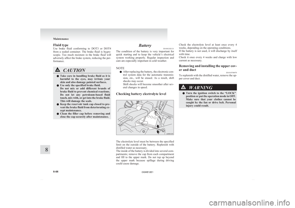
Checking battery electrolyte level The electrolyte level must be between the specified
limit
on the outside of the battery. Replenish with
distilled water as necessary.
The inside of the battery is divided into several com-
partments; remove the cap from each compartment
and fill to the upper mark. Do not top up beyond
the upper mark because spillage during driving
could cause damage. Check the electrolyte level at least once every 4
weeks, depending on the operating conditions.
If
the battery is not used, it will discharge by itself
with time.
Check it once every 4 weeks and charge with low
current as necessary.
Removing and installing the upper cov-
er and duct E01010700079
To replenish with the distilled water, remove the up-
per cover and duct. WARNING
l Turn
the ignition switch to the “LOCK”
position or put the operation mode in OFF.
Make sure that your clothes cannot be
caught by the fan or drive belt. Personal
injury could result. Maintenance
8-08
8
OGWE12E1
Page 331 of 378
No. Symbol Electrical system Capaci-
ties
6 Door locks 20 A
7 Radio 15 A
8 Control unit relay 7.5 A
9 Interior lamps
(Room lamps) 15 A
10 Hazard warning
flasher 15 A
11 Rear window wiper 15 A
12 Instruments 7.5 A
13 Cigarette lighter/
Accessory socket 15 A
14 Ignition switch 10 A
15 Sunroof 20 A
16 Outside rear-view
mirrors 10 A
17 4-wheel drive sys-
tem 10 A
18 Reversing lamps
(Backup lamps) 7.5 A
19 Accessory socket 15 A
20 Electric window
control 30 A
*1
21 Rear window de-
mister 30 A
*1
*1 : Fusible link No. Symbol Electrical system Capaci-
ties
22 Heated door mirror 7.5 A
23 Passenger’s power
seat 25 (20) A
24 Driver’s power seat 25 (20) A
25 Heated seat 30 A
*1 : Fusible link l
Some fuses may not be installed on your ve-
hicle, depending on the vehicle model or spec-
ifications.
l The table above shows the main equipment
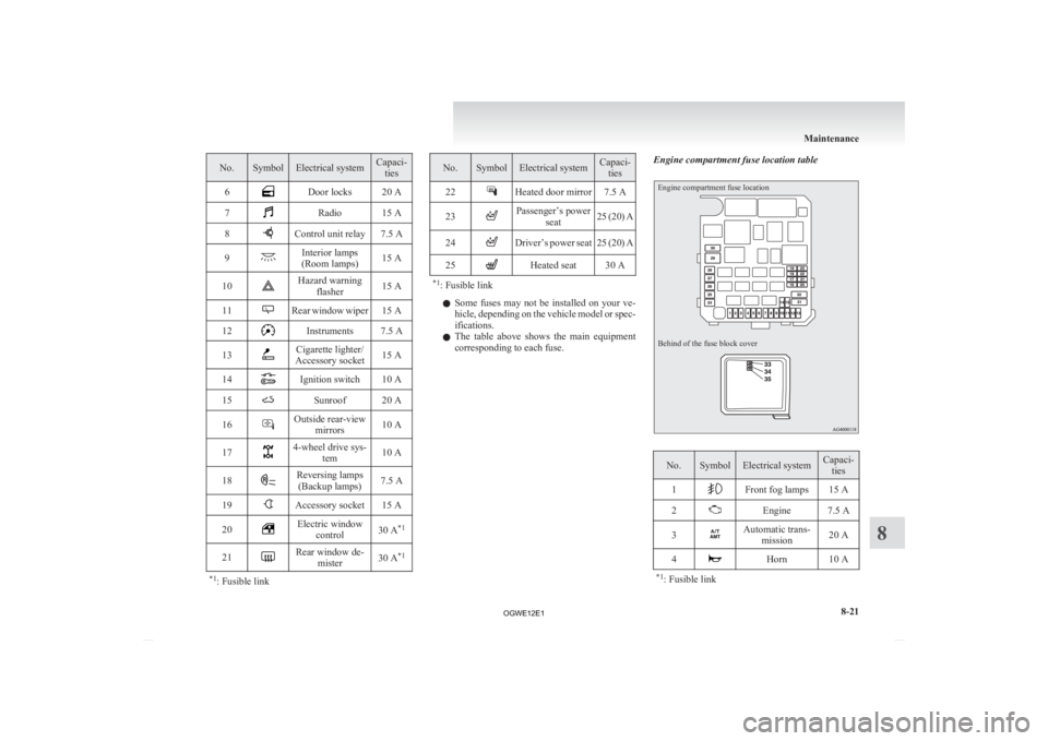
corresponding to each fuse. Engine compartment fuse location table
Engine compartment fuse location
Behind of the fuse block cover
No. Symbol Electrical system Capaci-
ties
1 Front fog lamps 15 A
2 Engine 7.5 A
3 Automatic trans-
mission 20 A
4 Horn 10 A
*1 : Fusible link Maintenance
8-21 8
OGWE12E1
Page 332 of 378

No. Symbol Electrical system Capaci-
ties
5 Alternator 7.5 A
6 Headlamp washer 20 A
7 Air conditioning 10 A
8 ETV/Oil cooler fan
(Twin Clutch SST) 15 A
9 Security horn 20 A
10 Wiper de-icer 15 A
11 — ——
12 Electric tailgate 30 A
13 Daytime running
lamps 10 A
14 Headlamp high-
beam (left) 10 A
15 Headlamp high-
beam (right) 10 A
16 Head-
lamp low
beam (left) Dis-
charge 20 A
17 Head-
lamp low
beam
(right) Dis-
charge 20 A
*1 : Fusible link No. Symbol Electrical system Capaci-
ties
18 Head-
lamp low
beam (left) Halogen 10 A
19 Head-
lamp low
beam
(right) Halogen 10 A
20 ENG/POWER 10 A
21 Ignition coil 10 A
22 ENG/POWER 20 A
Fuel line heater 25 A
23 Fuel pump 15 A
24 Starter
30 A*1
25 — ——
26 Anti-lock brake
system 40 A
*1
27 Anti-lock brake
system 30 A
*1
28 Air conditioning
condenser fan mo- tor 30 A
*1
29 Radiator fan motor
40 A*1
*1 : Fusible link No. Symbol Electrical system Capaci-
ties
30 IOD IOD 30 A
31 Audio system amp 30 A
32 Diesel 30 A
33 — Spare fuse 10 A
34 — Spare fuse 15 A
35 — Spare fuse 20 A
*1 : Fusible link l
Some fuses may not be installed on your ve-
hicle, depending on the vehicle model or spec-
ifications.
l The table above shows the main equipment
corresponding to each fuse.
The fuse box does not contain spare 7.5 A, 25 A or
30 A fuses. If one of these fuses burns out, substi-
tute with the following fuse.
7.5 A: 10 A spare fuse
25 A: 20 A spare fuse
30 A: 30 A audio system amp fuse
When using a substitute fuse, replace with a fuse of
the correct capacity as soon as possible. Maintenance
8-22
8
OGWE12E1
Page 333 of 378

Identification of fuse
Capacity Colour
7.5 A Brown
10 A Red
15 A Blue
20 A Yellow
25 A Natural (White)
30 A Green (fuse type)/
Pink (fusible link type)
40 A Green (fusible link type) Fuse replacement
E01007800630
1. Before replacing a fuse, always turn off the
electrical circuit concerned and turn the igni-
tion switch to the “LOCK” position or put
the operation mode in OFF.
2. Remove the fuse puller (A) from the inside of the fuse box in the engine compartment. 3. Referring
to the fuse load capacity table,
check the fuse pertaining to the problem. B- Fuse is OK
C- Blown fuse
NOTE l If
any system does not function but the fuse
corresponding to that system is normal, there
may be a fault in the system elsewhere. We
recommend you to have your vehicle checked.
4. Use the fuse puller to insert a new fuse with the same capacity. Make sure you insert the
fuse into the same location in the fuse block. CAUTION
l
If
the newly inserted fuse blows again af-
ter a short time, we recommend you to
have the electrical system checked to find
the cause and rectify it.
l Never use a fuse with a larger capacity
than specified or a substitute (such as a ca-
ble or foil). Doing so could cause the cir-
cuit wires to overheat and create a fire. Maintenance
8-23 8
OGWE12E1
Page 346 of 378

Vehicle labeling
E01100103069
Vehicle identification number
The
vehicle identification number is stamped on
the bulkhead as shown in the illustration. Vehicle information code plate
The
vehicle information code plate is riveted as
shown in the illustration.
Type 1
Type 2 The plate shows model code, engine model, trans-
mission model and body colour code, etc.
Please
use this number when ordering replacement
parts. 1- Model code
2-
Engine model code
3- Transmission model code
4- Body colour code
5- Interior code
6- Option code
7- Exterior code Vehicle identification number plate
(RHD vehicles only)
The
vehicle identification number is stamped on
the plate riveted to the left front corner of the vehi-
cle body. It is visible from outside of the vehicle
through the windscreen. Engine number
The
engine number is stamped on the engine cylin-
der block as shown in the illustrations.
Petrol-powered vehicles
1600 models *: Front of the vehicleSpecifications
9-02
9
OGWE12E1