headlamp MITSUBISHI ASX 2012 Owner's Manual (in English)
[x] Cancel search | Manufacturer: MITSUBISHI, Model Year: 2012, Model line: ASX, Model: MITSUBISHI ASX 2012Pages: 378, PDF Size: 18.2 MB
Page 4 of 378
Instruments and controls
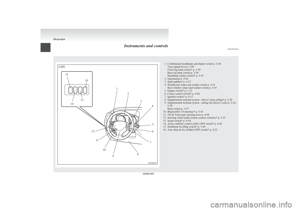
E00100106164 1. Combination headlamps and dipper switch p. 3-44
Turn-signal lever p. 3-49
Front fog lamp switch* p. 3-50
Rear fog lamp switch p. 3-50
Headlamp washer switch* p. 3-55
2.
Instruments p. 3-02
3. Shift paddles* p. 4-27
4. Windscreen wiper and washer switch p. 3-51 Rear window wiper and washer switch p. 3-55
5. Engine switch* p. 1-12
6. Cruise control switch* p. 4-44
7. Ignition switch* p. 4-12
8. Supplemental restraint system - driver’s knee airbag* p. 2-28
9. Supplemental restraint system - airbag (for driver’s seat) p. 2-24, 2-28
Horn switch p. 3-57
10. Bluetooth® 2.0 interface* p. 5-41
11. Tilt & Telescopic steering lever p. 4-08
12. Steering wheel audio remote control switches* p. 5-33
13. Sonar switch* p. 4-50
14. Active stability control (ASC) OFF switch* p. 4-42
15. Headlamp levelling switch* p. 3-48
16. Auto Stop & Go (AS&G) OFF switch* p. 4-22 OverviewLHD12
34
5
6
7
8
9
10
11
12
13
14
15
16
OGWE12E1
Page 5 of 378
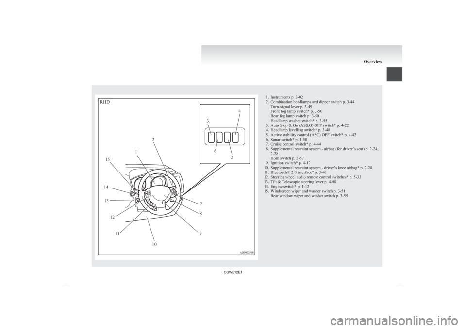
1. Instruments p. 3-02
2.
Combination headlamps and dipper switch p. 3-44Turn-signal lever p. 3-49
Front fog lamp switch* p. 3-50
Rear fog lamp switch p. 3-50
Headlamp washer switch* p. 3-55
3. Auto Stop & Go (AS&G) OFF switch* p. 4-22
4. Headlamp levelling switch* p. 3-48
5. Active stability control (ASC) OFF switch* p. 4-42
6. Sonar switch* p. 4-50
7. Cruise control switch* p. 4-44
8. Supplemental restraint system - airbag (for driver’s seat) p. 2-24, 2-28
Horn switch p. 3-57
9. Ignition switch* p. 4-12
10. Supplemental restraint system - driver’s knee airbag* p. 2-28
11. Bluetooth® 2.0 interface* p. 5-41
12. Steering wheel audio remote control switches* p. 5-33
13. Tilt & Telescopic steering lever p. 4-08
14. Engine switch* p. 1-12
15. Windscreen wiper and washer switch p. 3-51 Rear window wiper and washer switch p. 3-55 OverviewRHD12 3
4
5
6
7
8
9
10
11
12
13
14 15
OGWE12E1
Page 14 of 378
Exterior
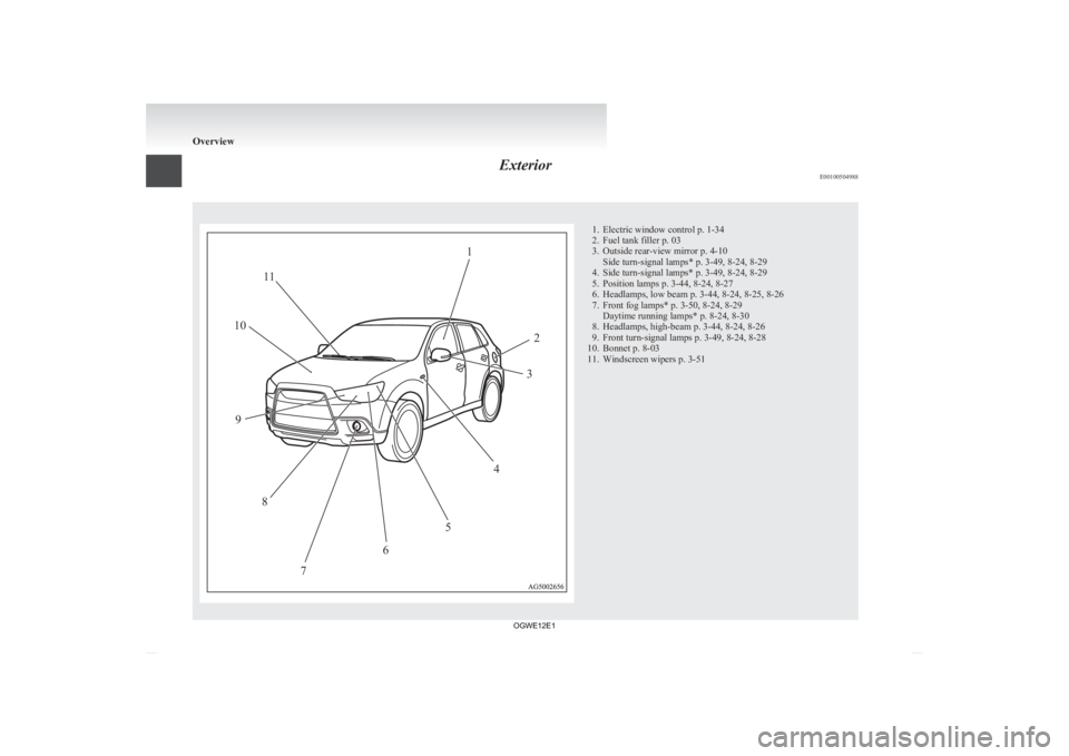
E00100504988 1. Electric window control p. 1-34
2.
Fuel tank filler p. 03
3. Outside rear-view mirror p. 4-10 Side turn-signal lamps* p. 3-49, 8-24, 8-29
4. Side turn-signal lamps* p. 3-49, 8-24, 8-29
5. Position lamps p. 3-44, 8-24, 8-27
6. Headlamps, low beam p. 3-44, 8-24, 8-25, 8-26
7. Front fog lamps* p. 3-50, 8-24, 8-29 Daytime running lamps* p. 8-24, 8-30
8. Headlamps, high-beam p. 3-44, 8-24, 8-26
9. Front turn-signal lamps p. 3-49, 8-24, 8-28
10. Bonnet p. 8-03
11. Windscreen wipers p. 3-51 Overview12
3
4
5
6
7
8
9
10
11
OGWE12E1
Page 30 of 378
Each time the door and tailgate unlock function is
set,
a chime will sound to tell you the condition of
the door and tailgate unlock function. Number of
chimes Condition
One chime All doors and the tailgate unlock
Two chimes Driver’s door unlock only 1. Remove the key from the ignition switch.
2. Place
the combination headlamps and dipper
switch in the “OFF” position, and leave the
driver’s door open.
3. Press and hold the LOCK switch (1) for 4 to 10 seconds and then also press the UNLOCK
switch (2) during this time.
4. Release in sequence the LOCK and UN- LOCK switches within 10 seconds of press-
ing the LOCK switch in step 3.
NOTE l On vehicles equipped with MITSUBISHI
Multi-Communication System (MMCS),
screen operations can be used to make the ad-
justment. Refer to the separate owner’s man-
ual for details.
Procedure for replacing the remote
control switch battery E00309500145
1. Before
replacing the battery, remove static
electricity from your body by touching a met-
al part such as a doorknob of the room. 2. Remove
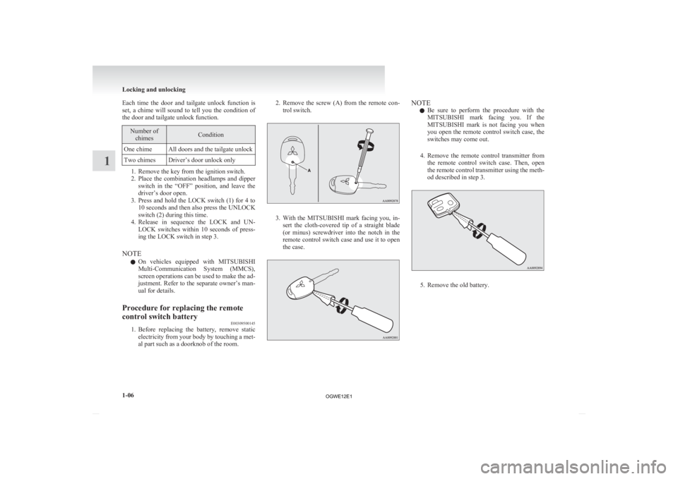
the screw (A) from the remote con-
trol switch. 3. With
the MITSUBISHI mark facing you, in-
sert the cloth-covered tip of a straight blade
(or minus) screwdriver into the notch in the
remote control switch case and use it to open
the case. NOTE
l Be
sure to perform the procedure with the
MITSUBISHI mark facing you. If the
MITSUBISHI mark is not facing you when
you open the remote control switch case, the
switches may come out.
4. Remove the remote control transmitter from the remote control switch case. Then, open
the remote control transmitter using the meth-
od described in step 3. 5. Remove the old battery.Locking and unlocking
1-06
1
OGWE12E1
Page 44 of 378
l
The remote control switch will operate with-
in approximately 4 m from the vehicle. How-
ever, the operating range of the remote con-
trol switch may change if the vehicle is loca-
ted near a power station, or radio/TV broad-
casting station.
l If either of the following problems occurs,
the battery may be exhausted.
• The remote control switch is operated atthe correct distance from the vehicle, but
the doors and tailgate are not locked/un-
locked in response.
• The indication lamp (3) is dim or does not come on.
For further information, please contact
your MITSUBISHI MOTORS Author-
ized Service Point.
If you replace the battery yourself, refer
to “Procedure for replacing the remote
control switch battery” on page 1-20.
l If your remote control switch is lost or dam-
aged, please contact your MITSUBISHI
MOTORS Authorized Service Point for a re-
placement remote control switch.
l If you wish to add a remote control switch,
please contact your MITSUBISHI MOTORS
Authorized Service Point. A maximum of 4
remote control switches are available for
your vehicle.
Setting of door and tailgate unlock function (Ex-
cept for vehicles equipped with a Dead Lock Sys-
tem) E00310400199
The door and tailgate unlock function can be set to
the following two conditions. Each time the door and tailgate unlock function is
set,
a chime will sound to tell you the condition of
the door and tailgate unlock function. Number of
chimes Condition
One chime All doors and the tailgate unlock
Two chimes Driver’s door unlock only 1. Put the operation mode in OFF.
2. Place
the combination headlamps and dipper
switch in the “OFF” position, and leave the
driver’s door open.
3. Press and hold the LOCK switch (1) for 4 to 10 seconds and then also press the UNLOCK
switch (2) during this time.
4. Release in sequence the LOCK and UN- LOCK switches within 10 seconds of press-
ing the LOCK switch in step 3.
NOTE l On vehicles equipped with MITSUBISHI
Multi-Communication System (MMCS),
screen operations can be used to make the ad-
justment. Refer to the separate owner’s man-
ual for details.
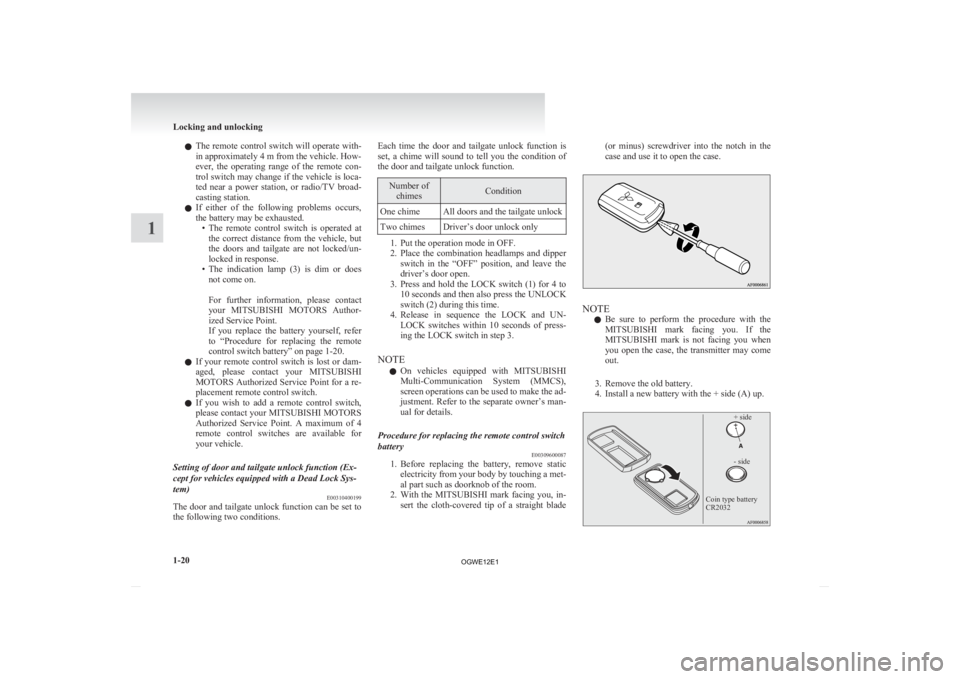
Procedure for replacing the remote control switch
battery E00309600087
1. Before
replacing the battery, remove static
electricity from your body by touching a met-
al part such as doorknob of the room.
2. With the MITSUBISHI mark facing you, in- sert the cloth-covered tip of a straight blade (or minus) screwdriver into the notch in the
case and use it to open the case.
NOTE
l Be
sure to perform the procedure with the
MITSUBISHI mark facing you. If the
MITSUBISHI mark is not facing you when
you open the case, the transmitter may come
out.
3. Remove the old battery.
4. Install a new battery with the + side (A) up.
+ side
- side
Coin type battery
CR2032 Locking and unlocking
1-20
1
OGWE12E1
Page 97 of 378
Instruments...................................................................................
3-02
Multi-information display .............................................................3-03
Indication lamp, warning lamp, and information screen display list.................................................................................3-24
Indication lamps ........................................................................... 3-39
Warning lamps .............................................................................. 3-40
Information screen display ........................................................... 3-41
Combination headlamps and dipper switch ..................................3-44
Headlamp levelling ....................................................................... 3-48
Turn-signal lever...........................................................................3-49
Hazard warning flasher switch ..................................................... 3-49
Fog lamp switch............................................................................3-50
Wiper and washer switch .............................................................. 3-51
Headlamp washer switch* ............................................................ 3-55
Rear window demister switch.......................................................3-56
Horn switch...................................................................................3-57 Instruments and controls
3
OGWE12E1
Page 122 of 378
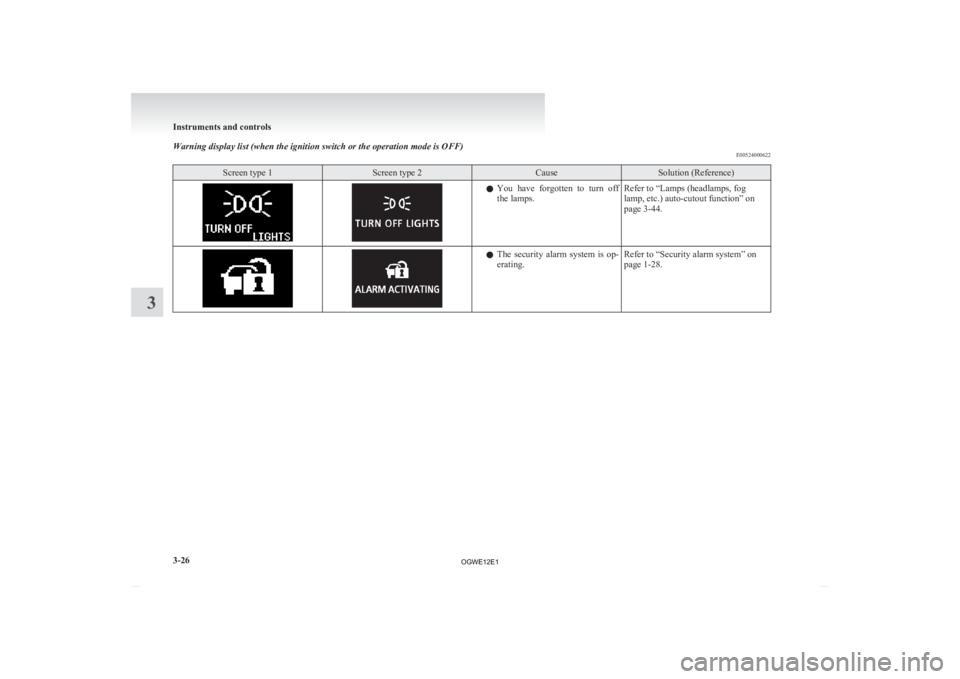
Warning display list (when the ignition switch or the operation mode is OFF)
E00524000622Screen type 1 Screen type 2 Cause Solution (Reference)
l
You have forgotten to turn off
the lamps. Refer to “Lamps (headlamps, fog
lamp, etc.) auto-cutout function” on
page 3-44. l
The
security alarm system is op-
erating. Refer to “Security alarm system” on
page 1-28.Instruments and controls
3-26
3
OGWE12E1
Page 130 of 378
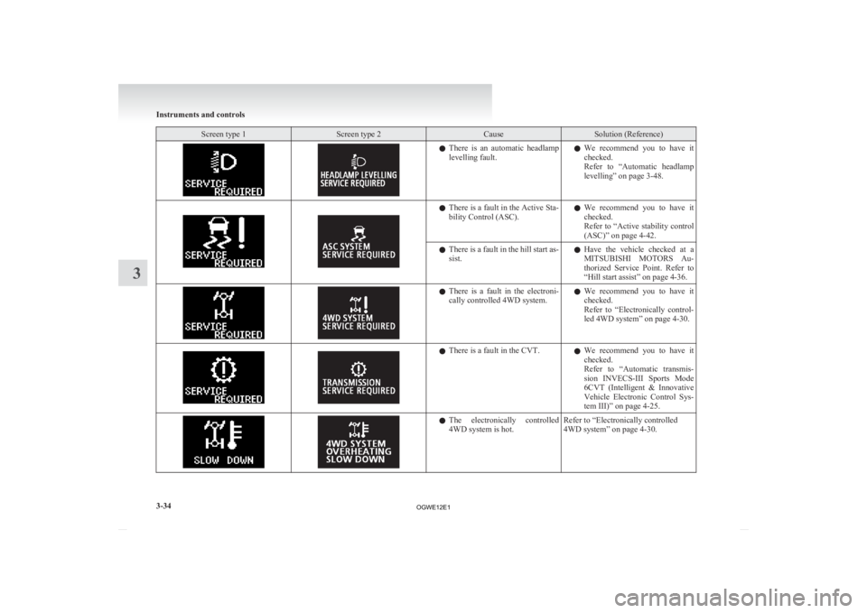
Screen type 1 Screen type 2 Cause Solution (Reference)
l
There is an automatic headlamp
levelling fault. l
We recommend you to have it
checked.
Refer to “Automatic headlamp
levelling” on page 3-48. l
There
is a fault in the Active Sta-
bility Control (ASC). l
We recommend you to have it
checked.
Refer to “Active stability control
(ASC)” on page 4-42.
l There
is a fault in the hill start as-
sist. l
Have the vehicle checked at a
MITSUBISHI MOTORS Au-
thorized Service Point. Refer to
“Hill start assist” on page 4-36. l
There
is a fault in the electroni-
cally controlled 4WD system. l
We recommend you to have it
checked.
Refer to “Electronically control-
led 4WD system” on page 4-30. l
There is a fault in the CVT.
lWe
recommend you to have it
checked.
Refer to “Automatic transmis-
sion INVECS-III Sports Mode
6CVT (Intelligent & Innovative
Vehicle Electronic Control Sys-
tem III)” on page 4-25. l
The
electronically controlled
4WD system is hot. Refer to “Electronically controlled
4WD system” on page 4-30.Instruments and controls
3-34
3
OGWE12E1
Page 140 of 378
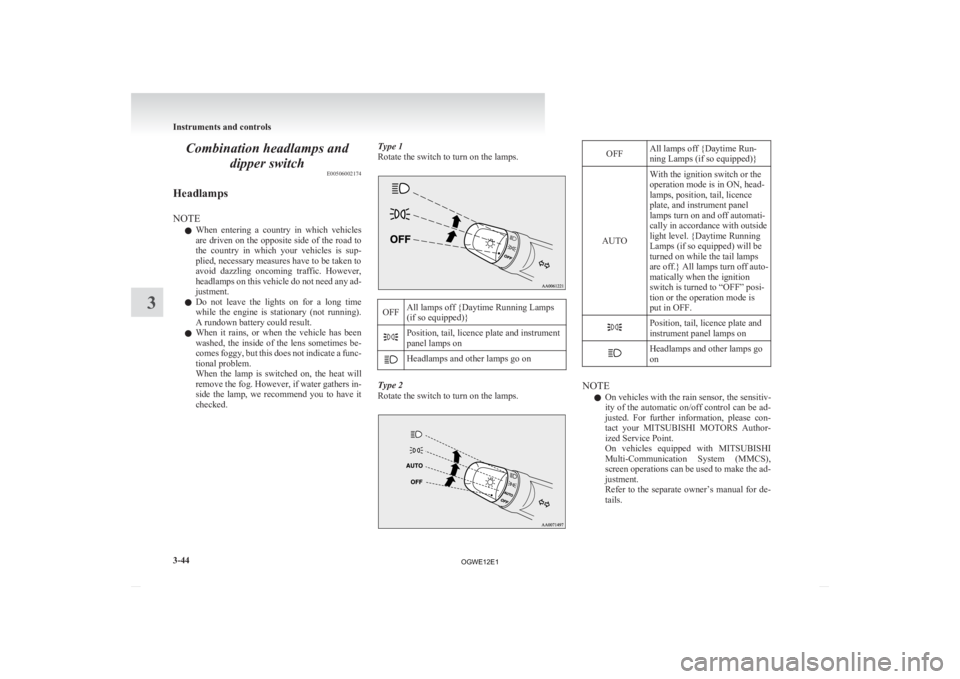
Combination headlamps and
dipper switch E00506002174
Headlamps
NOTE l When
entering a country in which vehicles
are driven on the opposite side of the road to
the country in which your vehicles is sup-
plied, necessary measures have to be taken to
avoid dazzling oncoming traffic. However,
headlamps on this vehicle do not need any ad-
justment.
l Do not leave the lights on for a long time
while the engine is stationary (not running).
A rundown battery could result.
l When it rains, or when the vehicle has been
washed, the inside of the lens sometimes be-
comes foggy, but this does not indicate a func-
tional problem.
When the lamp is switched on, the heat will
remove the fog. However, if water gathers in-
side the lamp, we recommend you to have it
checked. Type 1
Rotate the switch to turn on the lamps. OFF
All lamps off {Daytime Running Lamps
(if so equipped)} Position, tail, licence plate and instrument
panel lamps on
Headlamps and other lamps go on
Type 2
Rotate the switch to turn on the lamps. OFF
All lamps off {Daytime Run-
ning Lamps (if so equipped)}
AUTO With the ignition switch or the
operation mode is in ON, head-
lamps, position, tail, licence
plate, and instrument panel
lamps turn on and off automati-
cally in accordance with outside
light level. {Daytime Running
Lamps (if so equipped) will be
turned on while the tail lamps
are
off.} All lamps turn off auto-
matically when the ignition
switch is turned to “OFF” posi-
tion or the operation mode is
put in OFF. Position, tail, licence plate and
instrument panel lamps on
Headlamps and other lamps go
on
NOTE
l On vehicles with the rain sensor, the sensitiv-
ity
of the automatic on/off control can be ad-
justed. For further information, please con-
tact your MITSUBISHI MOTORS Author-
ized Service Point.
On vehicles equipped with MITSUBISHI
Multi-Communication System (MMCS),
screen operations can be used to make the ad-
justment.
Refer to the separate owner’s manual for de-
tails. Instruments and controls
3-44
3
OGWE12E1
Page 141 of 378
l
When the headlamps are turned off by the au-
tomatic on/off control with the ignition
switch in the “ON” position, the front fog
lamps (if so equipped) and rear fog lamps al-
so go off. When the headlamps are subse-
quently turned back on by the automatic on/
off control, the front fog lamps also come on
but the rear fog lamp stays off. If you wish to
turn the rear fog lamp back on, operate the
switch again.
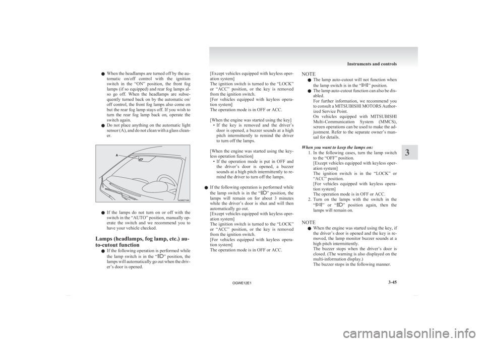
l Do not place anything on the automatic light
sensor (A), and do not clean with a glass clean-
er. l
If
the lamps do not turn on or off with the
switch in the “AUTO” position, manually op-
erate the switch and we recommend you to
have your vehicle checked.
Lamps (headlamps, fog lamp, etc.) au-
to-cutout function l If the following operation is performed while
the lamp switch is in the “ ”
position, the
lamps will automatically go out when the driv-
er’s door is opened. [Except
vehicles equipped with keyless oper-
ation system]
The ignition switch is turned to the “LOCK”
or “ACC” position, or the key is removed
from the ignition switch.
[For vehicles equipped with keyless opera-
tion system]
The operation mode is in OFF or ACC.
[When the engine was started using the key]
• If the key is removed and the driver’sdoor is opened, a buzzer sounds at a high
pitch intermittently to remind the driver
to turn off the lamps.
[When the engine was started using the key-
less operation function] • If the operation mode is put in OFF andthe driver’s door is opened, a buzzer
sounds at a high pitch intermittently to re-
mind the driver to turn off the lamps.
l If the following operation is performed while
the lamp switch is in the “ ”
position, the
lamps will remain on for about 3 minutes
while the driver’s door is shut and will then
automatically go out.
[Except vehicles equipped with keyless oper-
ation system]
The ignition switch is turned to the “LOCK”
or “ACC” position, or the key is removed
from the ignition switch.
[For vehicles equipped with keyless opera-
tion system]
The operation mode is in OFF or ACC. NOTE
l The
lamp auto-cutout will not function when
the lamp switch is in the “ ” position.
l The
lamp auto-cutout function can also be dis-
abled.
For further information, we recommend you
to consult a MITSUBISHI MOTORS Author-
ized Service Point.
On vehicles equipped with MITSUBISHI
Multi-Communication System (MMCS),
screen operations can be used to make the ad-
justment. Refer to the separate owner’s man-
ual for details.
When you want to keep the lamps on: 1. In the following cases, turn the lamp switchto the “OFF” position.
[Except vehicles equipped with keyless oper-
ation system]
The ignition switch is in the “LOCK” or
“ACC” position.
[For vehicles equipped with keyless opera-
tion system]
The operation mode is in OFF or ACC.
2. Turn on the lamps with the switch in the
“ ”
or “ ” position again, then the
lamps will remain on.
NOTE l When the engine was started using the key, if
the driver’s door is opened and the key is re-
moved, the lamp monitor buzzer sounds at a
high pitch intermittently.
The buzzer stops when the driver’s door is
closed. (The warning is also displayed on the
multi-information display.)
The buzzer stops in the following manner. Instruments and controls
3-45 3
OGWE12E1