Engine MITSUBISHI ASX 2014 (in English) Owners Manual
[x] Cancel search | Manufacturer: MITSUBISHI, Model Year: 2014, Model line: ASX, Model: MITSUBISHI ASX 2014Pages: 418, PDF Size: 14.02 MB
Page 215 of 418
Rear
Electric power steeringsystem (EPS) E00629200226
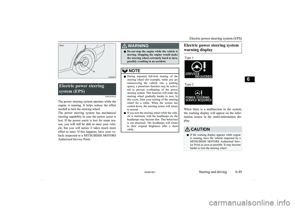
The power steering system operates while theengine is running. It helps reduce the effort
needed to turn the steering wheel.
The power steering system has mechanical
steering capability in case the power assist is lost. If the power assist is lost for some rea-
son, you will still be able to steer your vehi-
cle, but you will notice it takes much more effort to steer. If this happens, have your ve-hicle inspected at a MITSUBISHI MOTORS
Authorized Service Point.
WARNINGl Do not stop the engine while the vehicle is
moving. Stopping the engine would make the steering wheel extremely hard to turn,
possibly resulting in an accident.NOTEl During repeated full-lock turning of the
steering wheel (for example, while you are manoeuvring the vehicle into a parking space), a protection function may be activa-
ted to prevent overheating of the power steering system. This function will make the
steering wheel gradually harder to turn. In
this event, limit your turning of the steering wheel for a while. When the system has
cooled down, the steering action will return to normal.
l If you turn the steering wheel while the vehi-
cle is stationary with the headlamps on, the
headlamps may become dim. This behaviour is not abnormal. The headlamps will returnto their original brightness after a shortwhile.Electric power steering system
warning displayType 1Type 2
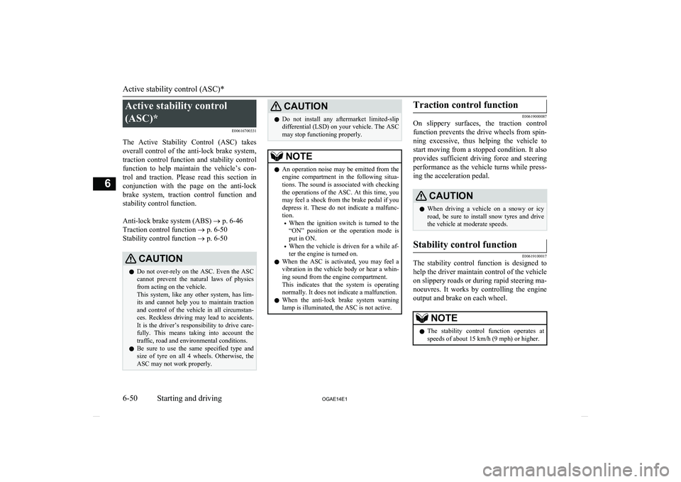
When there is a malfunction in the system, the warning display will appear on the infor-
mation screen in the multi-information dis-
play.
CAUTIONl If the warning display appears while engine
is running, have the vehicle inspected by a
MITSUBISHI MOTORS Authorized Serv-
ice Point as soon as possible. It may become
harder to turn the steering wheel.
Electric power steering system (EPS)
6-49
OGAE14E1Starting and driving6
Page 216 of 418
Active stability control
(ASC)* E00616700331
The Active Stability Control (ASC) takes
overall control of the anti-lock brake system, traction control function and stability control
function to help maintain the vehicle’s con-
trol and traction. Please read this section in conjunction with the page on the anti-lock
brake system, traction control function and stability control function.
Anti-lock brake system (ABS) ® p. 6-46
Traction control function ® p. 6-50
Stability control function ® p. 6-50CAUTIONl Do not over-rely on the ASC. Even the ASC
cannot prevent the natural laws of physics
from acting on the vehicle.
This system, like any other system, has lim-
its and cannot help you to maintain traction and control of the vehicle in all circumstan- ces. Reckless driving may lead to accidents. It is the driver’s responsibility to drive care-
fully. This means taking into account the traffic, road and environmental conditions.
l Be sure to use the same specified type and
size of tyre on all 4 wheels. Otherwise, the ASC may not work properly.CAUTIONl Do not install any aftermarket limited-slip
differential (LSD) on your vehicle. The ASC
may stop functioning properly.NOTEl An operation noise may be emitted from the
engine compartment in the following situa-
tions. The sound is associated with checking the operations of the ASC. At this time, you
may feel a shock from the brake pedal if you depress it. These do not indicate a malfunc-
tion.
• When the ignition switch is turned to the
“ON” position or the operation mode is
put in ON.
• When the vehicle is driven for a while af-
ter the engine is turned on.
l When the ASC is activated, you may feel a
vibration in the vehicle body or hear a whin- ing sound from the engine compartment.
This indicates that the system is operating
normally. It does not indicate a malfunction.
l When the anti-lock brake system warning
lamp is illuminated, the ASC is not active.Traction control function
E00619000087
On slippery surfaces, the traction control
function prevents the drive wheels from spin-
ning excessive, thus helping the vehicle to start moving from a stopped condition. It also
provides sufficient driving force and steering performance as the vehicle turns while press-
ing the acceleration pedal.
CAUTIONl When driving a vehicle on a snowy or icy
road, be sure to install snow tyres and drive
the vehicle at moderate speeds.Stability control function
E00619100017
The stability control function is designed to
help the driver maintain control of the vehicle
on slippery roads or during rapid steering ma-
noeuvres. It works by controlling the engine output and brake on each wheel.
NOTEl The stability control function operates at
speeds of about 15 km/h (9 mph) or higher.
Active stability control (ASC)*
6-50 OGAE14E1Starting and driving6
Page 217 of 418
“ASC OFF” switch
E00619200353
The ASC is automatically activated when the
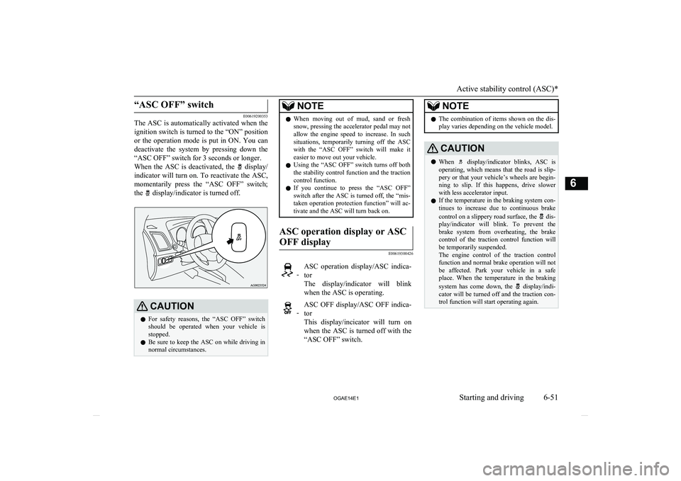
ignition switch is turned to the “ON” position or the operation mode is put in ON. You candeactivate the system by pressing down the
“ASC OFF” switch for 3 seconds or longer.
When the ASC is deactivated, the
display/
indicator will turn on. To reactivate the ASC, momentarily press the “ASC OFF” switch;
the
display/indicator is turned off.
CAUTIONl For safety reasons, the “ASC OFF” switch
should be operated when your vehicle is stopped.
l Be sure to keep the ASC on while driving in
normal circumstances.NOTEl When moving out of mud, sand or fresh
snow, pressing the accelerator pedal may not
allow the engine speed to increase. In such
situations, temporarily turning off the ASC with the “ASC OFF” switch will make it
easier to move out your vehicle.
l Using the “ASC OFF” switch turns off both
the stability control function and the traction control function.
l If you continue to press the “ASC OFF”
switch after the ASC is turned off, the “mis-
taken operation protection function” will ac- tivate and the ASC will turn back on.ASC operation display or ASC
OFF display
E00619300426
-ASC operation display/ASC indica- tor
The display/indicator will blink when the ASC is operating. -ASC OFF display/ASC OFF indica-
tor
This display/incicator will turn on when the ASC is turned off with the “ASC OFF” switch.NOTEl The combination of items shown on the dis-
play varies depending on the vehicle model.CAUTIONl When display/indicator blinks, ASC is
operating, which means that the road is slip- pery or that your vehicle’s wheels are begin-
ning to slip. If this happens, drive slower with less accelerator input.
l If the temperature in the braking system con-
tinues to increase due to continuous brake
control on a slippery road surface, the
dis-
play/indicator will blink. To prevent the
brake system from overheating, the brake
control of the traction control function will
be temporarily suspended.
The engine control of the traction control
function and normal brake operation will not be affected. Park your vehicle in a safeplace. When the temperature in the braking
system has come down, the
display/indi-
cator will be turned off and the traction con- trol function will start operating again.
Active stability control (ASC)*
6-51
OGAE14E1Starting and driving6
Page 218 of 418
NOTElThe display/indicator may turn on when
you start the engine. This means that the bat- tery voltage momentarily dropped when the
engine was started. It does not indicate a malfunction, provided that the display goes out immediately.
l When a compact spare tyre has been put on
your vehicle, the gripping ability of the tyre
will be lower, making it more likely that the
display/indicator will blink.
ASC warning display
E00619400443
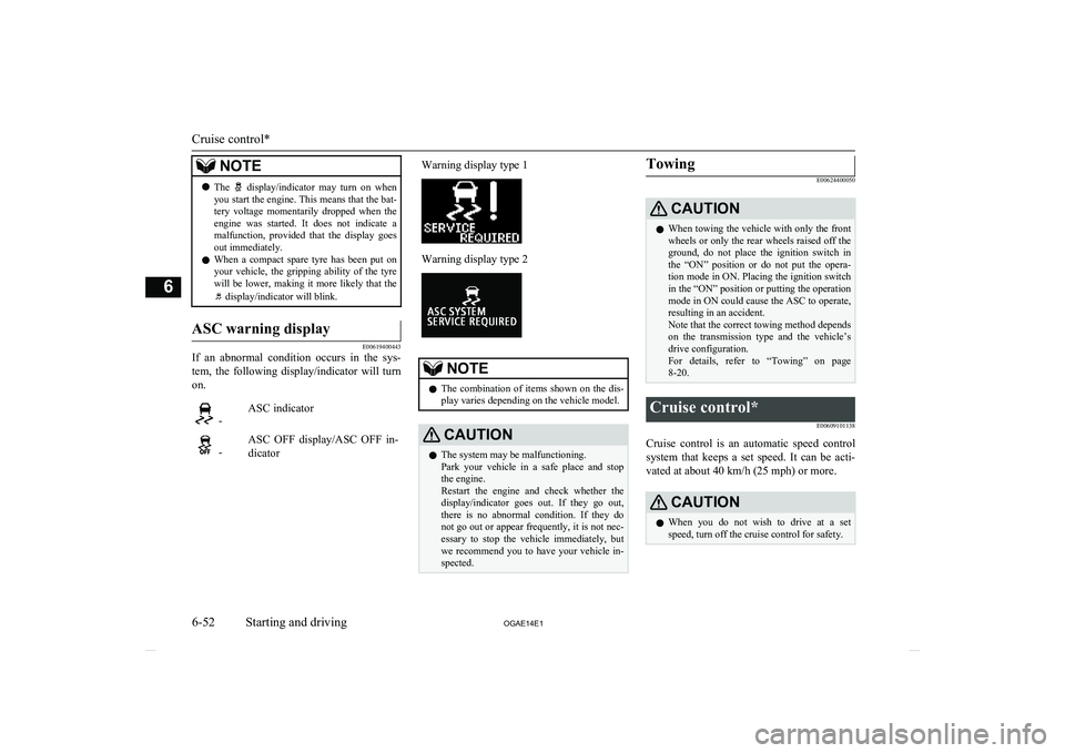
If an abnormal condition occurs in the sys-
tem, the following display/indicator will turn
on.
-ASC indicator -ASC OFF display/ASC OFF in-
dicatorWarning display type 1Warning display type 2NOTEl The combination of items shown on the dis-
play varies depending on the vehicle model.CAUTIONl The system may be malfunctioning.
Park your vehicle in a safe place and stop
the engine.
Restart the engine and check whether the display/indicator goes out. If they go out,
there is no abnormal condition. If they do not go out or appear frequently, it is not nec- essary to stop the vehicle immediately, but
we recommend you to have your vehicle in- spected.Towing
E00624400050CAUTIONl When towing the vehicle with only the front
wheels or only the rear wheels raised off the
ground, do not place the ignition switch in the “ON” position or do not put the opera- tion mode in ON. Placing the ignition switchin the “ON” position or putting the operation
mode in ON could cause the ASC to operate, resulting in an accident.
Note that the correct towing method depends
on the transmission type and the vehicle’s drive configuration.
For details, refer to “Towing” on page 8-20.Cruise control*
E00609101138
Cruise control is an automatic speed controlsystem that keeps a set speed. It can be acti-vated at about 40 km/h (25 mph) or more.
CAUTIONl When you do not wish to drive at a set
speed, turn off the cruise control for safety.
Cruise control*
6-52 OGAE14E1Starting and driving6
Page 219 of 418
CAUTIONlDo not use cruise control when driving con-
ditions will not allow you to stay at the same speed, such as in heavy traffic or on roads
that are winding, icy, snow-covered, wet, slippery, on a steep downhill slope.
l On vehicles with
M/T, do not move the
gearshift lever to the “N” (Neutral) position
while driving at a set speed without depress- ing the clutch pedal. The engine will run too
fast and might be damaged.NOTEl Cruise control may not be able to keep your
speed on uphills or downhills.
l Your speed may decrease on a steep uphill.
You may use the accelerator pedal if you
want to stay at your set speed.
l Your speed may increase to more than the
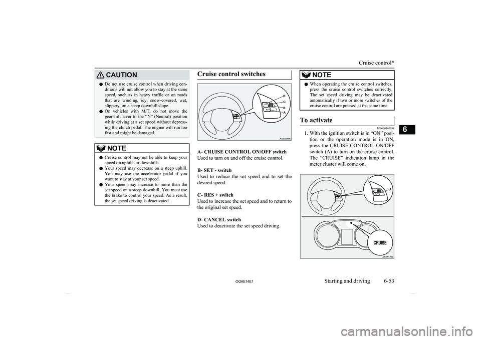
set speed on a steep downhill. You must use the brake to control your speed. As a result, the set speed driving is deactivated.Cruise control switches
A- CRUISE CONTROL ON/OFF switch
Used to turn on and off the cruise control.
B- SET - switch
Used to reduce the set speed and to set the
desired speed.
C- RES + switch
Used to increase the set speed and to return to
the original set speed.
D- CANCEL switch
Used to deactivate the set speed driving.
NOTEl When operating the cruise control switches,
press the cruise control switches correctly.
The set speed driving may be deactivated automatically if two or more switches of the
cruise control are pressed at the same time.To activate
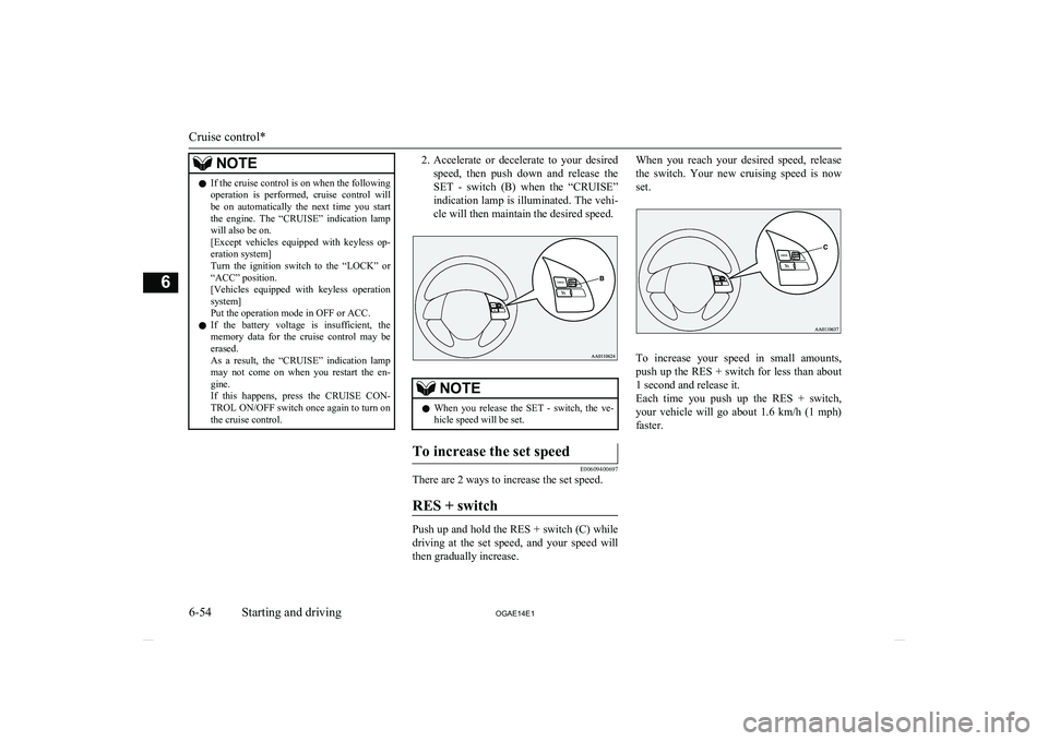
E00609301198
1. With the ignition switch is in “ON” posi-
tion or the operation mode is in ON,press the CRUISE CONTROL ON/OFF
switch (A) to turn on the cruise control. The “CRUISE” indication lamp in the meter cluster will come on.
Cruise control*
6-53
OGAE14E1Starting and driving6
Page 220 of 418
NOTElIf the cruise control is on when the following
operation is performed, cruise control will be on automatically the next time you start the engine. The “CRUISE” indication lamp
will also be on.
[Except vehicles equipped with keyless op- eration system]
Turn the ignition switch to the “LOCK” or
“ACC” position.
[Vehicles equipped with keyless operation
system]
Put the operation mode in OFF or ACC.
l If the battery voltage is insufficient, the
memory data for the cruise control may be
erased.
As a result, the “CRUISE” indication lamp may not come on when you restart the en-
gine.
If this happens, press the CRUISE CON-
TROL ON/OFF switch once again to turn on
the cruise control.2. Accelerate or decelerate to your desired
speed, then push down and release the SET - switch (B) when the “CRUISE”
indication lamp is illuminated. The vehi- cle will then maintain the desired speed.NOTEl When you release the SET - switch, the ve-
hicle speed will be set.To increase the set speed
E00609400697
There are 2 ways to increase the set speed.
RES + switch
Push up and hold the RES + switch (C) whiledriving at the set speed, and your speed will
then gradually increase.
When you reach your desired speed, release
the switch. Your new cruising speed is now
set.
To increase your speed in small amounts,
push up the RES + switch for less than about 1 second and release it.
Each time you push up the RES + switch,
your vehicle will go about 1.6 km/h (1 mph) faster.
Cruise control*
6-54 OGAE14E1Starting and driving6
Page 223 of 418
WARNINGlOn vehicles equipped with
A/T, CVT, al-
though the set speed driving will be deac-
tivated when shifting to the “N” (NEU-
TRAL) position, never move the selector lever to the “N” (NEUTRAL) position
while driving.
You would have no engine braking and
could cause a serious accident.
Also, the set speed driving may be deactiva-
ted as follows:
l When the engine speed rises and ap-
proaches the tachometer's red zone (the red-coloured part of the tachometer di- al).
CAUTIONl When the set speed driving is deactivated
automatically in any situation other than those listed above, there may be a systemmalfunction.
Press the CRUISE CONTROL ON/OFF switch to turn off the cruise control and have your vehicle inspected by a MITSUBISHI
MOTORS Authorized Service Point.To resume the set speed
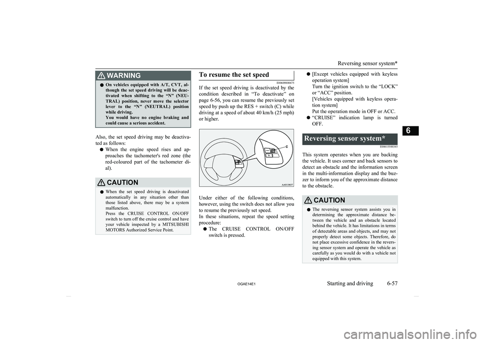
E00609800675
If the set speed driving is deactivated by the
condition described in “To deactivate” on
page 6-56, you can resume the previously set
speed by push up the RES + switch (C) while
driving at a speed of about 40 km/h (25 mph)
or higher.
Under either of the following conditions, however, using the switch does not allow you
to resume the previously set speed.
In these situations, repeat the speed setting procedure:
l The CRUISE CONTROL ON/OFF
switch is pressed.
l [Except vehicles equipped with keyless
operation system]
Turn the ignition switch to the “LOCK”
or “ACC” position.
[Vehicles equipped with keyless opera- tion system]
Put the operation mode in OFF or ACC.
l “CRUISE” indication lamp is turned
OFF.Reversing sensor system*
E00615500345
This system operates when you are backingthe vehicle. It uses corner and back sensors to detect an obstacle and the information screen
in the multi-information display and the buz-
zer to inform you of the approximate distance to the obstacle.
CAUTIONl The reversing sensor system assists you in
determining the approximate distance be-
tween the vehicle and an obstacle located behind the vehicle. It has limitations in terms
of detectable areas and objects, and may not
properly detect some objects. Therefore, do not place excessive confidence in the revers-
ing sensor system and operate the vehicle as carefully as you would do with a vehicle not equipped with this system.
Reversing sensor system*
6-57
OGAE14E1Starting and driving6
Page 225 of 418
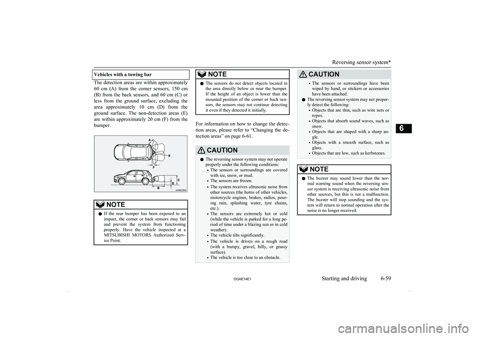
Vehicles with a towing bar
The detection areas are within approximately60 cm (A) from the corner sensors, 150 cm
(B) from the back sensors, and 60 cm (C) or less from the ground surface, excluding the
area approximately 10 cm (D) from the
ground surface. The non-detection areas (E) are within approximately 20 cm (F) from thebumper.
NOTEl If the rear bumper has been exposed to an
impact, the corner or back sensors may failand prevent the system from functioning
properly. Have the vehicle inspected at a
MITSUBISHI MOTORS Authorized Serv-
ice Point.NOTEl The sensors do not detect objects located in
the area directly below or near the bumper. If the height of an object is lower than the
mounted position of the corner or back sen-
sors, the sensors may not continue detecting it even if they detected it initially.
For information on how to change the detec-
tion areas, please refer to “Changing the de- tection areas” on page 6-61.
CAUTIONl The reversing sensor system may not operate
properly under the following conditions:
• The sensors or surroundings are covered
with ice, snow, or mud.
• The sensors are frozen.
• The system receives ultrasonic noise from
other sources (the horns of other vehicles, motorcycle engines, brakes, radios, pour-
ing rain, splashing water, tyre chains, etc.).
• The sensors are extremely hot or cold
(while the vehicle is parked for a long pe- riod of time under a blazing sun or in coldweather).
• The vehicle tilts significantly.
• The vehicle is driven on a rough road
(with a bumpy, gravel, hilly, or grassy surface).
• The vehicle is too close to an obstacle.CAUTION•The sensors or surroundings have been
wiped by hand, or stickers or accessorieshave been attached.
l The reversing sensor system may not proper-
ly detect the following:
• Objects that are thin, such as wire nets or
ropes.
• Objects that absorb sound waves, such as
snow.
• Objects that are shaped with a sharp an-
gle.
• Objects with a smooth surface, such as
glass.
• Objects that are low, such as kerbstones.NOTEl The buzzer may sound lower than the nor-
mal warning sound when the reversing sen-sor system is receiving ultrasonic noise from
other sources, but this is not a malfunction.
The buzzer will stop sounding and the sys- tem will return to normal operation after thenoise is no longer received.
Reversing sensor system*
6-59
OGAE14E1Starting and driving6
Page 227 of 418
NOTElWhen the sensors detect different obstacles
at the same time, the information screen in the multi-information display indicates the directions of the obstacles each sensor is de-
tecting. However, closer obstacles are given priority over other detected obstacles and the
warning buzzer sounds to inform you of
closer obstacles.Changing the detection areas
E00615800159
The detection areas can be changed as fol-
lows:
Vehicles with a towing bar
While the operation of the system is stopped
at the “SONAR” switch, push the “SONAR”
switch approximately 3 seconds or more, and release it. The buzzer sounds twice to indi-
cate that the detection area has been changed.
Vehicles without a towing bar
While the operation of the system is stopped at the “SONAR” switch, push the “SONAR”
switch approximately 3 seconds or more, and
release it. The buzzer sounds once to indicate that the detection area has been changed.
NOTEl The detection area will not change if you
keep the “SONAR” switch pushed for
10 seconds or more.
l After pushing the “SONAR” switch, revers-
ing sensor system operation differs accord- ing to the detection area setting.
• Setting when towing bar is not equipped
When the gearshift lever or selector lever
is moved to the “R” position, the revers-
ing sensor system will operate even if cor- ner sensor operation was stopped by push-
ing the “SONAR” switch.
• Setting when towing bar is equipped
When reversing sensor system operation was stopped by pushing the “SONAR”
switch, the reversing sensor system will not operate until the engine has been stop- ped even if the gearshift lever or selector
lever is moved to the “R” position.
To resume reversing sensor system opera- tion, push the “SONAR” switch or stop and restart the engine, and then move the
gearshift lever or selector lever to the “R” position.Reversing sensor system warn-
ing display
E00615900277
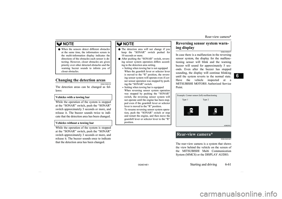
In case there is a malfunction in the reversing
sensor system, the display for the malfunc-
tioning sensor will blink and the warning buzzer will sound for approximately 5 sec-
onds. Even after the buzzer has stopped sounding, the display will continue blinking
until the system reverts to the normal state. Have the vehicle inspected at aMITSUBISHI MOTORS Authorized Service
Point.
Example: Corner sensor (left) mulfunctioningType 2Type 1
Rear-view camera*
E00618401687
The rear-view camera is a system that showsthe view behind the vehicle on the screen of
the MITSUBISHI Multi Communication
System (MMCS) or the DISPLAY AUDIO.
Rear-view camera*
6-61
OGAE14E1Starting and driving6
Page 232 of 418
NOTElTo prevent wind noise or reduction in fuel
economy, remove the roof carrier when not
in use.
l Remove the roof carrier before using an au-
tomatic car wash.
l Be sure that adequate clearance is main-
tained for raising the tailgate when installing a roof carrier.Trailer towing
E00610000680
In order to tow a trailer with your vehicle,
have a trailer towing device that meets all rel- evant regulations in your area, mounted con-sult a MITSUBISHI MOTORS Authorized
Service Point.
The regulations concerning the towing of a
trailer may differ from country to country. You are advised to obey the regulations in each area.
CAUTIONl Danger of Accident!
A towing bar should be fitted according to MITSUBISHI MOTORS guidelines.Maximum towable weight with
brake and maximum trailer- nose weight
Never exceed the maximum towable weight
with brake and the maximum trailer-nose weight as listed in the specifications.
(Refer to page 11-07.)
If you tow a trailer at an altitude of more than
1,000 m above sea-level, reduce your weight by 10 % of the gross combination weight for
every increase of 1,000 m above sea-level, as
the engine output is lowered owing to de-
crease in atmospheric pressure.
Towing bar mounting specifi-
cations
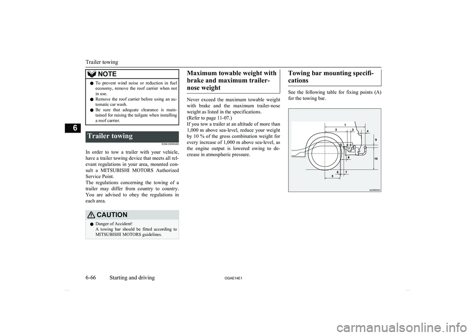
See the following table for fixing points (A) for the towing bar.
Trailer towing
6-66 OGAE14E1Starting and driving6