display MITSUBISHI ASX 2015 (in English) Owners Manual
[x] Cancel search | Manufacturer: MITSUBISHI, Model Year: 2015, Model line: ASX, Model: MITSUBISHI ASX 2015Pages: 452, PDF Size: 20.1 MB
Page 228 of 452
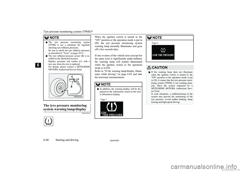
NOTElThe tyre pressure monitoring system
(TPMS) is not a substitute for regularlychecking tyre inflation pressures.
Be sure to check the tyre inflation pressures as described in “Tyres” on page 10-13.
l The tyre inflation pressure sensor (B) is in-
stalled in the illustrated location.
Replace grommet and washer (C) with a
new one when the tyre is replaced.
For details, please contact a MITSUBISHI
MOTORS Authorized Service Point.The tyre pressure monitoring
system warning lamp/display
E00637200111
When the ignition switch is turned to the
“ON” position or the operation mode is put in
ON, the tyre pressure monitoring system warning lamp normally illuminates and goes
off a few seconds later.
If one or more of the vehicle tyres (except for the spare tyre) is significantly under-inflated, the warning lamp will remain illuminated
while the ignition switch or the operation mode is in ON.
Refer to “If the warning lamp/display illumi-
nates while driving” on page 6-62 and take
the necessary measurements.NOTEl In addition, the warning display will be dis-
played on the information screen in the mul-
ti-information display.Type 1NOTEType 2CAUTIONl If the warning lamp does not illuminate
when the ignition switch is turned to the
“ON” position or the operation mode is put
in ON, it means that the tyre pressure moni-
toring system (TPMS) is not working prop- erly. Have the system inspected by a
MITSUBISHI MOTORS Authorized Serv-
ice Point.
In such situations, a malfunctioning of the system may prevent the monitoring of the tyre pressure. Avoid sudden braking, sharp
turning and high-speed driving.
Tyre pressure monitoring system (TPMS)*
6-60OGAE15E5Starting and driving6
Page 229 of 452
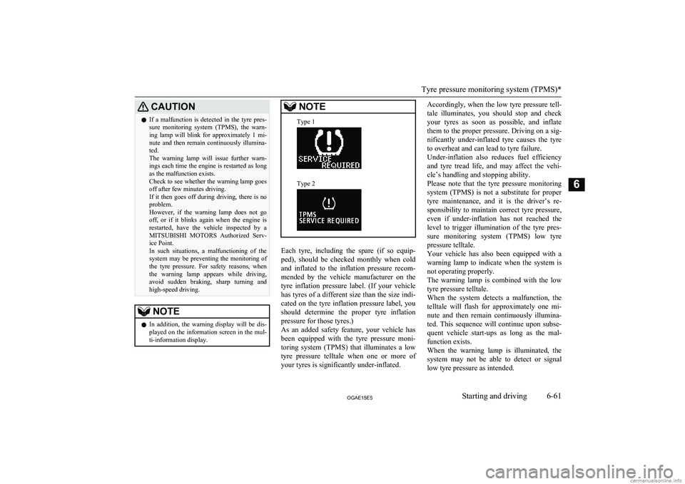
CAUTIONlIf a malfunction is detected in the tyre pres-
sure monitoring system (TPMS), the warn- ing lamp will blink for approximately 1 mi-
nute and then remain continuously illumina-
ted.
The warning lamp will issue further warn- ings each time the engine is restarted as long
as the malfunction exists.
Check to see whether the warning lamp goes
off after few minutes driving.
If it then goes off during driving, there is no
problem.
However, if the warning lamp does not go off, or if it blinks again when the engine is
restarted, have the vehicle inspected by a MITSUBISHI MOTORS Authorized Serv-
ice Point.
In such situations, a malfunctioning of the system may be preventing the monitoring of the tyre pressure. For safety reasons, when
the warning lamp appears while driving,
avoid sudden braking, sharp turning and high-speed driving.NOTEl In addition, the warning display will be dis-
played on the information screen in the mul-
ti-information display.NOTEType 1Type 2
Each tyre, including the spare (if so equip-
ped), should be checked monthly when cold and inflated to the inflation pressure recom-
mended by the vehicle manufacturer on the tyre inflation pressure label. (If your vehiclehas tyres of a different size than the size indi-
cated on the tyre inflation pressure label, you
should determine the proper tyre inflationpressure for those tyres.)
As an added safety feature, your vehicle has
been equipped with the tyre pressure moni- toring system (TPMS) that illuminates a low
tyre pressure telltale when one or more of
your tyres is significantly under-inflated.
Accordingly, when the low tyre pressure tell-
tale illuminates, you should stop and checkyour tyres as soon as possible, and inflate
them to the proper pressure. Driving on a sig- nificantly under-inflated tyre causes the tyre
to overheat and can lead to tyre failure.
Under-inflation also reduces fuel efficiency and tyre tread life, and may affect the vehi-
cle’s handling and stopping ability.
Please note that the tyre pressure monitoring system (TPMS) is not a substitute for proper
tyre maintenance, and it is the driver’s re- sponsibility to maintain correct tyre pressure,
even if under-inflation has not reached thelevel to trigger illumination of the tyre pres-
sure monitoring system (TPMS) low tyre
pressure telltale.
Your vehicle has also been equipped with a warning lamp to indicate when the system is
not operating properly.
The warning lamp is combined with the low
tyre pressure telltale.
When the system detects a malfunction, the
telltale will flash for approximately one mi- nute and then remain continuously illumina- ted. This sequence will continue upon subse-
quent vehicle start-ups as long as the mal-
function exists.
When the warning lamp is illuminated, the system may not be able to detect or signal
low tyre pressure as intended.
Tyre pressure monitoring system (TPMS)*
6-61OGAE15E5Starting and driving6
Page 230 of 452
The tyre pressure monitoring system (TPMS)
malfunctions may occur for a variety of rea- sons, including the installation of replace- ment or alternate tyres or wheels on the vehi-cle that prevent the tyre pressure monitoring
system (TPMS) from functioning properly.
Always check the tyre pressure monitoring system (TPMS) malfunction telltale after re- placing one or more tyres or wheels on yourvehicle to ensure that the replacement or al- ternate tyres and wheels allow the tyre pres-
sure monitoring system (TPMS) to continue to function properly.If the warning lamp/display il-
luminates while driving
E00637300037
1. If the warning lamp illuminates, avoid
hard braking, sharp steering manoeuvres
and high speeds. You should stop and adjust the tyres to the proper inflationpressure as soon as possible. Adjust the spare tyre at the same time. Refer to
“Tyres” on page 10-13
NOTEl In addition, the warning display will be dis-
played on the information screen in the mul-
ti-information display.
l When inspecting or adjusting the tyre pres-
sure, do not apply excessive force to the
valve stem to avoid breakage.NOTEl After inspecting or adjusting the tyre pres-
sure, always reinstall the valve cap on the
valve stem.
Without the valve cap, dirt or moisture could
get into the valve, resulting in damage to the tyre inflation pressure sensor.
l Do not use metal valve caps, which may
cause a metal reaction, resulting in corrosion and damage of the tyre inflation pressure
sensors.
l Once adjustments have been made, the
warning lamp will go off after a few minutesof driving.
2. If the warning lamp remains illuminated
after you have been driving for about 10
minutes after you adjust the tyre infla- tion pressure, one or more of the tyresmay have a puncture. Inspect the tyreand if it has a puncture, have it repaired
by a MITSUBISHI MOTORS Author-
ized Service Point as soon as possible.
WARNINGl If the warning lamp/display illuminates
while you are driving, avoid hard brak- ing, sharp steering manoeuvres and high speeds.
Driving with an under-inflated tyre ad-
versely affects vehicle performance and
can result in an accident.CAUTIONl The warning lamp/display may not illumi-
nate immediately in the event of a tyre blow- out or rapid leak.NOTEl To avoid the risk of damage to the tyre infla-
tion pressure sensors, have any punctured
tyre repaired by a MITSUBISHI MOTORS
Authorized Service Point. If the tyre repair is
not done by a MITSUBISHI MOTORS Au-
thorized Service Point, damage to the tyre
inflation pressure sensor is not covered by your warranty.
l Do not use an aerosol puncture-repair spray
on any tyre.
Such a spray could damage the tyre inflation
pressure sensors.
Have any puncture repaired by a MITSUBISHI MOTORS Authorized Serv-
ice Point.
l Using the tyre repair kit may damage the
tyre inflation pressure sensor. The vehiclemust promptly be inspected and repaired by
a MITSUBISHI MOTORS Authorized Serv-
ice Point.
The tyre pressure monitoring system (TPMS)
may not work normally in the following cir-
cumstances:
l A wireless facility or device using the
same frequency is near the vehicle.
Tyre pressure monitoring system (TPMS)*
6-62OGAE15E5Starting and driving6
Page 231 of 452
lSnow or ice is stuck inside the fenders
and/or on the wheels.
l The tyre inflation pressure sensor’s bat-
tery is dead.
l Wheels other than
MITSUBISHI
MOTORS GENUINE wheels are being
used.
l Wheels that are not fitted with tyre infla-
tion pressure sensors are being used.
l Wheels whose ID codes are not memo-
rized by the vehicle are used.
l A window tint that affects the radio
wave signals is installed.NOTEl Tyre inflation pressures vary with the ambi-
ent temperature. If the vehicle is subjected to large variations in ambient temperature, the tyre inflation pressures may be low (causing
the warning lamp/display to come on) when the ambient temperature is relatively low. If the warning lamp/display comes on, adjustthe tyre inflation pressure.Whenever the tyres and wheels
are replaced with new ones
E00637400025
If new wheels with new tyre inflation pres-
sure sensors are installed, their ID codes must be programmed into the tyre pressure moni- toring system. Have tyre and wheel replace-
ment performed by a MITSUBISHI
MOTORS Authorized Service Point to avoid
the risk of damaging the tyre inflation pres- sure sensors. If the wheel replacement is not
done by a MITSUBISHI MOTORS Author-
ized Service Point, it is not covered by your warranty.
CAUTIONl The use of non-genuine wheels will prevent
the proper fit of the tyre inflation pressure sensors, resulting air leakage or damage of
the sensors.Reset of low tyre pressure
warning threshold
E00637500039
The threshold is set based on the tyre pres- sure which the reset function is executed by
following procedure.
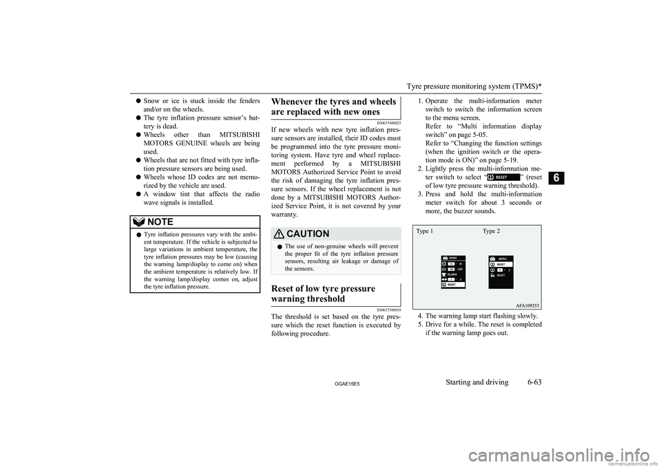
1. Operate the multi-information meter
switch to switch the information screen
to the menu screen.
Refer to “Multi information display switch” on page 5-05.
Refer to “Changing the function settings (when the ignition switch or the opera- tion mode is ON)” on page 5-19.
2. Lightly press the multi-information me-
ter switch to select “
” (reset
of low tyre pressure warning threshold).
3. Press and hold the multi-information
meter switch for about 3 seconds or
more, the buzzer sounds.
4. The warning lamp start flashing slowly.
5. Drive for a while. The reset is completed
if the warning lamp goes out.
Tyre pressure monitoring system (TPMS)*
6-63OGAE15E5Starting and driving6 Type 1 Type 2
Page 232 of 452
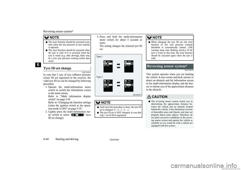
NOTElThe reset function should be executed every
time when the tyre pressure or tyre rotationis adjusted.
l The reset function should be executed when
the tyre is cold. If it is executed when the
tyre is warm (e.g. after driving), there may be a low tyre pressure warning earlier than
usual.Tyre ID set change
E00637600030
In case that 2 sets of tyre inflation pressure
sensor ID are registered in the receiver, the
valid tyre ID set can be changed by following
procedure. 1. Operate the multi-information meter
switch to switch the information screen
to the menu screen.
Refer to “Multi information display switch” on page 5-05
Refer to “Changing the function settings (when the ignition switch or the opera-
tion mode is ON)” on page 5-19
2. Lightly press the multi-information me-
ter switch to select “
” (tyre
ID set change).
3. Press and hold the multi-information
meter switch for about 3 seconds or more.
The setting changes the selected tyre ID set.NOTEl Each time this procedure is done, the tyre ID
set is changed. (1 - 2 - 1 - 2 …)
l The tyre ID set is NOT changed, in case that
only 1 set of ID is registered.NOTEl When changing the tyre ID set, the reset
function of low tyre pressure warning threshold is automatically started. (The
warning lamp start flashing slowly.) If the
tyre is warm at this time. the reset function should be executed again when the tyre iscold.Reversing sensor system*
E00615500345
This system operates when you are backingthe vehicle. It uses corner and back sensors to detect an obstacle and the information screen
in the multi-information display and the buz-
zer to inform you of the approximate distance to the obstacle.
CAUTIONl The reversing sensor system assists you in
determining the approximate distance be-
tween the vehicle and an obstacle located behind the vehicle. It has limitations in terms
of detectable areas and objects, and may not
properly detect some objects. Therefore, do not place excessive confidence in the revers-
ing sensor system and operate the vehicle as carefully as you would do with a vehicle not equipped with this system.
Reversing sensor system*
6-64OGAE15E5Starting and driving6 Type 1
Type 2
Page 235 of 452
Warning for obstacles
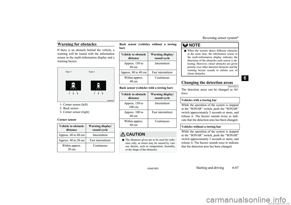
If there is an obstacle behind the vehicle, a
warning will be issued with the information screen in the multi-information display and a
warning buzzer.
Type 2Type 1
1- Corner sensor (left)
2- Back sensor
3- Corner sensor (right)
Corner sensor
Vehicle to obstacle distanceWarning display/sound cycleApprox. 60 to 40 cmIntermittentApprox. 40 to 20 cmFast intermittentWithin approx. 20 cmContinuousBack sensor (vehicles without a towing
bar)Vehicle to obstacle distanceWarning display/sound cycleApprox. 150 to 80 cmIntermittentApprox. 80 to 40 cmFast intermittentWithin approx.40 cmContinuous
Back sensor (vehicles with a towing bar)
Vehicle to obstacle distanceWarning display/sound cycleApprox. 150 to 100 cmIntermittentApprox. 100 to 60 cmFast intermittentWithin approx.60 cmContinuousCAUTIONlThe distances given are to be used for refer-
ence only, as errors may be caused by vari- ous factors, such as temperature, humidity,
or the shape of the obstacles.NOTEl When the sensors detect different obstacles
at the same time, the information screen in the multi-information display indicates the directions of the obstacles each sensor is de-
tecting. However, closer obstacles are given priority over other detected obstacles and the
warning buzzer sounds to inform you of
closer obstacles.Changing the detection areas
E00615800159
The detection areas can be changed as fol-
lows:
Vehicles with a towing bar
While the operation of the system is stopped
at the “SONAR” switch, push the “SONAR”
switch approximately 3 seconds or more, and release it. The buzzer sounds twice to indi-
cate that the detection area has been changed.
Vehicles without a towing bar
While the operation of the system is stopped at the “SONAR” switch, push the “SONAR”
switch approximately 3 seconds or more, and
release it. The buzzer sounds once to indicate that the detection area has been changed.
Reversing sensor system*
6-67OGAE15E5Starting and driving6
Page 236 of 452
NOTElThe detection area will not change if you
keep the “SONAR” switch pushed for
10 seconds or more.
l After pushing the “SONAR” switch, revers-
ing sensor system operation differs accord- ing to the detection area setting.
• Setting when towing bar is not equipped
When the gearshift lever or selector lever
is moved to the “R” position, the revers-
ing sensor system will operate even if cor- ner sensor operation was stopped by push-
ing the “SONAR” switch.
• Setting when towing bar is equipped
When reversing sensor system operation was stopped by pushing the “SONAR”
switch, the reversing sensor system will not operate until the engine has been stop- ped even if the gearshift lever or selector
lever is moved to the “R” position.
To resume reversing sensor system opera- tion, push the “SONAR” switch or stop and restart the engine, and then move the
gearshift lever or selector lever to the “R” position.Reversing sensor system warn-
ing display
E00615900277
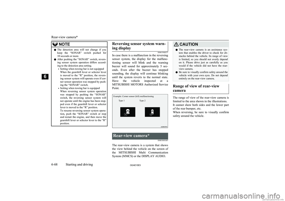
In case there is a malfunction in the reversing
sensor system, the display for the malfunc-
tioning sensor will blink and the warning buzzer will sound for approximately 5 sec-
onds. Even after the buzzer has stopped sounding, the display will continue blinking
until the system reverts to the normal state. Have the vehicle inspected at aMITSUBISHI MOTORS Authorized Service
Point.
Example: Corner sensor (left) mulfunctioningType 2Type 1
Rear-view camera*
E00618401687
The rear-view camera is a system that showsthe view behind the vehicle on the screen of
the MITSUBISHI Multi Communication
System (MMCS) or the DISPLAY AUDIO.
CAUTIONl The rear-view camera is an assistance sys-
tem that enables the driver to check for ob- stacles behind the vehicle. Its range of view
is limited, so you should not overly depend on it. Please drive just as carefully as you
would if the vehicle did not have the rear-
view camera.
l Be sure to visually confirm safety around the
vehicle with your own eyes. Do not depend entirely on the rear-view camera.
Range of view of rear-view
camera
The range of view of the rear-view camera is
limited to the area shown in the illustrations.
It cannot show both sides and the lower part of the rear bumper, etc.
When reversing, be sure to visually confirm
safety around the vehicle.
Rear-view camera*
6-68OGAE15E5Starting and driving6
Page 237 of 452
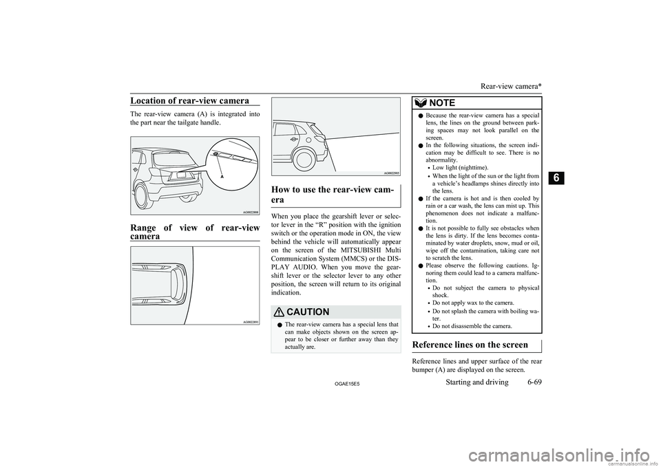
Location of rear-view camera
The rear-view camera (A) is integrated intothe part near the tailgate handle.
Range of view of rear-viewcamera
How to use the rear-view cam-
era
When you place the gearshift lever or selec- tor lever in the “R” position with the ignition
switch or the operation mode in ON, the view behind the vehicle will automatically appear
on the screen of the MITSUBISHI Multi
Communication System (MMCS) or the DIS-
PLAY AUDIO. When you move the gear-
shift lever or the selector lever to any other position, the screen will return to its originalindication.
CAUTIONl The rear-view camera has a special lens that
can make objects shown on the screen ap- pear to be closer or further away than they
actually are.NOTEl Because the rear-view camera has a special
lens, the lines on the ground between park-
ing spaces may not look parallel on the screen.
l In the following situations, the screen indi-
cation may be difficult to see. There is no abnormality.
• Low light (nighttime).
• When the light of the sun or the light from
a vehicle’s headlamps shines directly into
the lens.
l If the camera is hot and is then cooled by
rain or a car wash, the lens can mist up. This
phenomenon does not indicate a malfunc- tion.
l It is not possible to fully see obstacles when
the lens is dirty. If the lens becomes conta- minated by water droplets, snow, mud or oil,
wipe off the contamination, taking care not to scratch the lens.
l Please observe the following cautions. Ig-
noring them could lead to a camera malfunc-
tion.
• Do not subject the camera to physical
shock.
• Do not apply wax to the camera.
• Do not splash the camera with boiling wa-
ter.
• Do not disassemble the camera.
Reference lines on the screen
Reference lines and upper surface of the rear
bumper (A) are displayed on the screen.
Rear-view camera*
6-69OGAE15E5Starting and driving6
Page 238 of 452
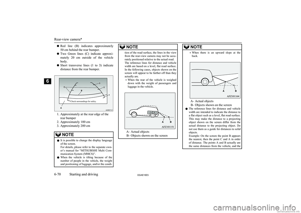
lRed line (B) indicates approximately
50 cm behind the rear bumper.
l Two Green lines (C) indicate approxi-
mately 20 cm outside of the vehicle
body.
l Short transverse lines (1 to 3) indicate
distance from the rear bumper.Check surroundings for safety.
1. Approximately at the rear edge of the rear bumper
2. Approximately 100 cm
3. Approximately 200 cm
NOTEl It is possible to change the display language
of the screen.
For details, please refer to the separate own- er’s manual for “ MITSUBISHI Multi Com-
munication System (MMCS)”.
l When the vehicle is tilting because of the
number of people in the vehicle, the weight
and positioning of luggage, and/or the condi-NOTEtion of the road surface, the lines in the view from the rear-view camera may not be accu-
rately positioned relative to the actual road.
The reference lines for distance and vehicle
width are based on a level, flat road surface. In the following cases, objects shown on the
screen will appear to be farther off than they actually are.
• When the rear of the vehicle is weighed
down with the weight of passengers and
luggage in the vehicle.
A- Actual objects
B- Objects shown on the screen
NOTE• When there is an upward slope at the
back.
A- Actual objects
B- Objects shown on the screen
l The reference lines for distance and vehicle
width are intended to indicate the distance to
a flat object such as a level, flat road surface. This may make the distance to a projectingobject shown on the screen differ from the
actual distance to the projecting object. Do not use them as a guide for distances to solid
objects.
Example: On the screen the point B appears
the nearest, then the point C and A in order of distance. The points A and B actually are the same distances from the vehicle, and the
Rear-view camera*
6-70OGAE15E5Starting and driving6
Page 242 of 452
lTo make full use of engine braking,
change to a lower shift point before de-
scending a slope.
Additional precautions for vehi- cles equipped with an A/T or
CVT
It is recommended the “D” position on slopes
or at low speed.
Use the sports mode in mountainous areas in order to make better use of engine braking
and to assist the brake system. However, be
sure that the speed does not exceed the maxi- mum speed limit for the selected shift posi- tion.
Overheating
This will normally occur as a result of some
mechanical failure. If your vehicle should overheat, stop and check for a loose or bro-
ken water pump/alternator drive belt, a blocked radiator air intake or a low coolant
level. If these items are satisfactory the over-
heating could be caused by a number of me-
chanical causes that would have to be
checked at a competent service centre.
CAUTIONl If the engine overheats, please refer to the
“Engine overheating” section of “For emer-
gencies” prior to taking any corrective ac- tion.
l On vehicles equipped with
A/T, CVT, if the
warning display is showing, the tempera-
ture of the automatic transmission fluid,
CVT fluid is high.
Read the reference page and take the re- quired measures.
Refer to “When a malfunction occurs in the
A/T” on page 6-30, “When a malfunction
occurs in the CVT” on page 6-37.
Trailer towing
6-74OGAE15E5Starting and driving6