stop start MITSUBISHI ASX 2017 (in English) Repair Manual
[x] Cancel search | Manufacturer: MITSUBISHI, Model Year: 2017, Model line: ASX, Model: MITSUBISHI ASX 2017Pages: 458, PDF Size: 22.98 MB
Page 297 of 458
Enabling and disabling thevoice model and retraining
E00727600100
You can turn a voice model registered with
the speaker enrollment function on and off whenever you want.
You can also retrain the system.
Use the following procedure to perform these
actions. 1. Press the SPEECH button.
2. Say “Voice training”.
3. If you have completed a speaker enroll-
ment process once already, the voice guide will say either “Enrollment is ena-
bled. Would you like to disable or re-
train?” or “Enrollment is disabled. Would you like to enable or retrain?”
4. When enrollment is “enabled”, the voice
model is on; when enrollment is “disa-
bled”, the voice model is off. Say the command that fits your needs.
Say “Retrain” to start the speaker enroll- ment process and recreate a new voice
model. (Refer to “Speaker enrollment”
on page 7-52.)
Connecting the Bluetooth ®
2.0
interface and Bluetooth ®
de-
vice
E00760601634
Before you can make or receive hands-free
calls or play music using the Bluetooth ®
2.0
interface function, you must pair the Blue-
tooth ®
device and Bluetooth ®
2.0 interface.
NOTEl Pairing is required only when the device is
used for the first time. Once the device has
been paired with the Bluetooth ®
2.0 inter-
face, you only need to bring the device into the vehicle next time and the device will au-
tomatically connect to the Bluetooth ®
2.0 in-
terface (if supported by the device). The de-
vice must have Bluetooth ®
turned ON to
connect.
Up to 7 Bluetooth ®
devices can be paired
with the Bluetooth ®
2.0 interface.
If multiple paired Bluetooth ®
devices are
available in the vehicle, the cellular phone or music player most recently connected is auto-
matically connected to the Bluetooth ®
2.0 in-
terface.
You can also change a Bluetooth ®
device to
be connected.
To pair
To pair a Bluetooth ®
device with the Blue-
tooth ®
2.0 interface, use either one of the fol-
lowing 2 methods (Type 1 or Type 2).
Pairing procedure- Type 1*
1. Stop your vehicle in a safe area, put the
gearshift lever in the “N” (Neutral) posi-
tion ( M/T) or the selector lever in the
“P” (PARK) position ( A/T or CVT) and
pull the parking brake lever.
NOTEl You cannot pair Bluetooth ®
devices with the
Bluetooth ®
2.0 interface unless the vehicle is
parked. Before pairing a Bluetooth ®
device
with the Bluetooth ®
2.0 interface, confirm
that the vehicle is parked in a safe location.
2. Press the SPEECH button.
3. Say “Setup”.
4. Say “Pairing options.”
5. The voice guide will say “Select one of
the following: pair, edit, delete, or list.” Say “Pair.”
Bluetooth ®
2.0 interface*
7-53OGAE17E2For pleasant driving7
Page 298 of 458
NOTElIf 7 devices have already been paired, the
voice guide will say “Maximum devicespaired” and then the system will end the
pairing process. To register a new device, delete one device and then repeat the pairing
process.
(Refer to “Selecting a device: Deleting a de- vice” on page 7-56.)
6. The voice guide will say “Please say a 4-
digit pairing code.” Say a 4-digit num- ber.
When the confirmation function is on, the system will confirm whether the
number said is acceptable. Answer
“Yes.”
Answer “No” to return to pairing code selection.
NOTEl Some Bluetooth ®
devices require a specific
pairing code. Please refer to the device man-
ual for pairing code requirements.NOTEl The pairing code entered here is only used
for the Bluetooth ®
connection certification.
It is any 4-digit number the user would like
to select.
Remember the pairing code as it needs to be
keyed into the Bluetooth ®
device later in the
pairing process.
Depending on the connection settings of the
Bluetooth ®
device, this code may have to be
entered each time you connect the Blue-
tooth ®
device to the Bluetooth ®
2.0 inter-
face. For the default connection settings, re-
fer to the instructions for the device.
7. The voice guide will say “Start pairing
procedure on the device. See the device manual for instructions.” Enter in the
Bluetooth ®
device the 4-digit number
you have registered in Step 6.
NOTEl According to the corresponding device to
Bluetooth ®
, it might take a few minutes to
pair the Bluetooth ®
device with the Blue-
tooth ®
2.0 interface.
l If the Bluetooth ®
2.0 interface cannot recog-
nize the Bluetooth ®
device, the voice guide
will say “Pairing has timed out” and the pairing process will be cancelled.
Confirm that the device you are pairing sup-
ports Bluetooth ®
, and try pairing it again.NOTEl If you enter the wrong number, the voice
guide will say “Pairing failed” and the pair-
ing process will be cancelled.
Confirm the number is right, and try pairing it again.
8. The voice guide will say “Please say the
name of the device after the beep.” You
can assign a desired name for the Blue-
tooth ®
device and register it as a device
tag. Say the name you want to register
after the beep.
NOTEl When the confirmation function is on, after
repeating the device tag you have said, the
voice guide will ask “Is this correct?” An-
swer “Yes.”
To change the device tag, answer “No” and then say the device tag again.
9. The voice guide will say “Pairing com-
plete,” and the pairing process will end.
Pairing procedure- Type 2*
1. Stop your vehicle in a safe area, put the
gearshift lever in the “N” (Neutral) posi- tion (M/T) , or the selector lever in the
“P” (PARK) position ( A/T or CVT), and
pull the parking brake lever.
Bluetooth ®
2.0 interface*
7-54OGAE17E2For pleasant driving7
Page 330 of 458
If the vehicle breaks downE00800101108
If the vehicle breaks down on the road, move it to the shoulder and turn on the hazard
warning flashers and set up a warning trian- gle, flashing lamp, etc.
Refer to “Hazard warning flasher switch” on
page 5-55.
If the engine stops/fails
Vehicle operation and control are affected if
the engine stops.
Before moving the vehicle to a safe area, be
aware of the following:
l The brake booster becomes inoperative
and the pedal effort will increase. Press down the brake pedal harder than usual.
l Since the power steering system is no
longer operative, the steering wheel feels
heavy when turning it.
Emergency starting
E00800504259
If the engine cannot be started because thebattery is weak or dead, the battery from an-other vehicle can be used with jumper cables to start the engine.
WARNINGl To start the engine by using jumper ca-
bles from another vehicle, perform thecorrect procedures according to the in-
struction below. Incorrect procedures could result in a fire or explosion or dam-
age to the vehicles.CAUTIONl Do not attempt to start the engine by pulling
or pushing the vehicle.
It could damage your vehicle.
l Always wear protective eye goggles when
working near the battery.
l Keep the battery out of the reach of children.
1.
Get the vehicles close enough so the
jumper cables can reach, but be sure the vehicles aren’t touching each other.
CAUTIONl Check the other vehicle. It must have a 12-
volt battery.
If the other system isn’t 12-volt, shorting can
damage both vehicles.
2. Turn off all lamps, heater and other elec-
trical loads.
3. Set the parking brake firmly on each ve-
hicle. Put an A/T, CVT in “P” (Park) or
a M/T in “N” (Neutral).
4. Turn the ignition switch to the “LOCK”
position or put the operation mode in
OFF.WARNINGl Perform step 4 on both vehicles before-
hand.
Make sure that the cables or your clothes
cannot be caught by the fan or drive belt.
Personal injury could result.
5. Make sure battery electrolyte is at the
proper level.
Refer to “Battery” on page 10-09.
WARNINGl If electrolyte fluid is not visible, or ap-
pears to be frozen, Do Not Attempt Jump
Starting!
A battery might rupture or explode if the temperature is below the freezing point orif it is not filled to the proper level.
6. Connect one end of one jumper cable to
the positive (+) terminal of the dis-charged battery (A), and the other end to
the positive (+) terminal of the booster
battery (B).
If the vehicle breaks down
8-02OGAE17E2For emergencies8
Page 332 of 458
CAUTIONlKeep the engine of the vehicle giving assis-
tance running.NOTEl For vehicles equipped with the Auto Stop &
Go (AS&G) system, press the “AS&G OFF”switch to deactivate the AS&G system and
prevent the engine from automatically stop- ping before the battery is sufficiently charg-
ed.
Refer to “To deactivate” on page 6-22.
9. After the engine is started, disconnect
the cables in the reverse order and keep the engine running for several minutes.
WARNINGl If the battery has to be charged while fit-
ted in the vehicle, disconnect the vehicle side negative (-) terminal connected to the
battery.
l Keep sparks, cigarettes and flames away
from the battery because the battery may produce an explosion.
l Use adequate ventilation when charging
or using the battery in an enclosed space.
l Remove all the caps before charging the
battery.WARNINGl Electrolyte is corrosive diluted sulphuric
acid.
If electrolyte (battery acid) comes into contact with your hands, eyes, clothes and
the painted surface of your vehicle, it should be thoroughly flushed with water.If electrolyte gets in your eyes, flush them
with water immediately and thoroughly, and get prompt medical attention.NOTEl If the vehicle is put in motion without fully
charging the battery, it might cause the loss
of smooth engine operation and the anti-lock brake warning lamp to illuminate.
Refer to “Anti-lock brake system (ABS)” on
page 6-48.Engine overheating
E00800604090
When the engine is overheating, the informa-tion screen in the multi-information display
will be interrupted and the engine coolant
temperature warning display will appear. Al- so “
” will blink.
If this occurs, take the following corrective measures: 1. Stop the vehicle in a safe place.
2. Check whether steam is coming from the
engine compartment.
[If steam does not come from the engine
compartment]
With the engine still running, raise the
bonnet to ventilate the engine compart-
ment.NOTEl For vehicles equipped with the Auto Stop &
Go (AS&G) system, press the “AS&G OFF”switch to deactivate the AS&G system be-
fore stopping the vehicle.
Refer to “To deactivate” on page 6-22.
[If steam is coming from the engine
compartment]
Stop the engine, and when the steam
stops, raise the bonnet to ventilate the engine compartment. Restart the engine.
WARNINGl Do not open the bonnet while steam is
coming from the engine compartment. It
could cause steam or hot water to spurt out, causing burns. Hot water could spurt
out even when there is no steam coming out, and some parts will be very hot. Be
very careful when opening the bonnet.
Engine overheating
8-04OGAE17E2For emergencies8
Page 340 of 458
NOTElSimply putting sealant and air into the tyre
using the tyre repair kit does not seal the
puncture hole. Air will leak through the puncture hole until the emergency repair procedure is completed (through step 19 of
these instructions).
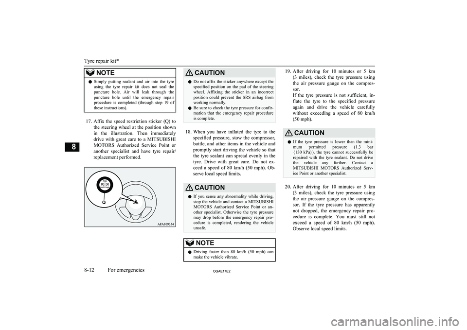
17. Affix the speed restriction sticker (Q) to
the steering wheel at the position shown
in the illustration. Then immediately drive with great care to a MITSUBISHI
MOTORS Authorized Service Point or
another specialist and have tyre repair/
replacement performed.
CAUTIONl Do not affix the sticker anywhere except the
specified position on the pad of the steeringwheel. Affixing the sticker in an incorrect
position could prevent the SRS airbag from working normally.
l Be sure to check the tyre pressure for confir-
mation that the emergency repair procedureis complete.
18. When you have inflated the tyre to the
specified pressure, stow the compressor,
bottle, and other items in the vehicle and
promptly start driving the vehicle so that the tyre sealant can spread evenly in the
tyre. Drive with great care. Do not ex- ceed a speed of 80 km/h (50 mph). Ob-
serve local speed limits.
CAUTIONl If you sense any abnormality while driving,
stop the vehicle and contact a MITSUBISHI
MOTORS Authorized Service Point or an-
other specialist. Otherwise the tyre pressure
may drop before the emergency repair pro- cedure is completed, rendering the vehicle
unsafe.NOTEl Driving faster than 80 km/h (50 mph)
can
make the vehicle vibrate.19. After driving for 10 minutes or 5 km
(3 miles), check the tyre pressure using
the air pressure gauge on the compres- sor.
If the tyre pressure is not sufficient, in-
flate the tyre to the specified pressure again and drive the vehicle carefully
without exceeding a speed of 80 km/h (50 mph).CAUTIONl If the tyre pressure is lower than the mini-
mum permitted pressure (1.3 bar {130 kPa}), the tyre cannot successfully be repaired with the tyre sealant. Do not drive
the vehicle any further. Contact a MITSUBISHI MOTORS Authorized Serv-
ice Point or another specialist.
20. After driving for 10 minutes or 5 km
(3 miles), check the tyre pressure using
the air pressure gauge on the compres- sor. If the tyre pressure has apparentlynot dropped, the emergency repair pro-
cedure is complete. You must still not exceed a speed of 80 km/h (50 mph) .
Observe local speed limits.
Tyre repair kit*
8-12OGAE17E2For emergencies8
Page 344 of 458
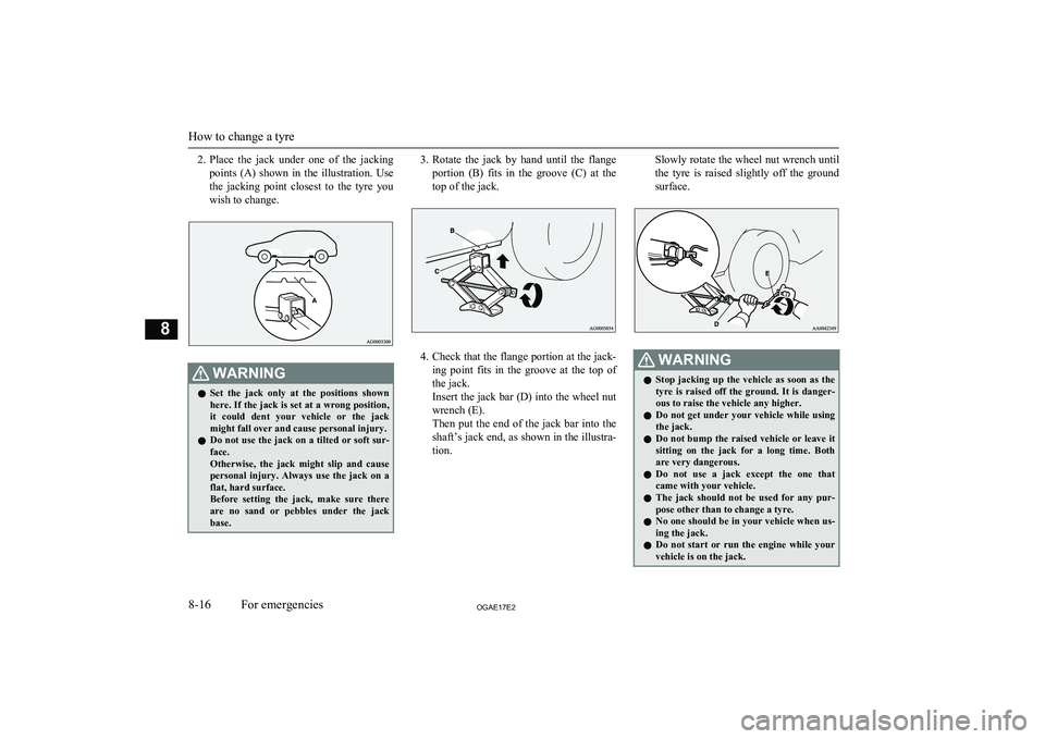
2.Place the jack under one of the jacking
points (A) shown in the illustration. Use
the jacking point closest to the tyre you wish to change.WARNINGl Set the jack only at the positions shown
here. If the jack is set at a wrong position, it could dent your vehicle or the jack
might fall over and cause personal injury.
l Do not use the jack on a tilted or soft sur-
face.
Otherwise, the jack might slip and cause
personal injury. Always use the jack on a flat, hard surface.
Before setting the jack, make sure there
are no sand or pebbles under the jack base.3. Rotate the jack by hand until the flange
portion (B) fits in the groove (C) at the
top of the jack.
4. Check that the flange portion at the jack-
ing point fits in the groove at the top of the jack.
Insert the jack bar (D) into the wheel nut
wrench (E).
Then put the end of the jack bar into the
shaft’s jack end, as shown in the illustra- tion.
Slowly rotate the wheel nut wrench until
the tyre is raised slightly off the ground
surface.WARNINGl Stop jacking up the vehicle as soon as the
tyre is raised off the ground. It is danger-
ous to raise the vehicle any higher.
l Do not get under your vehicle while using
the jack.
l Do not bump the raised vehicle or leave it
sitting on the jack for a long time. Both are very dangerous.
l Do not use a jack except the one that
came with your vehicle.
l The jack should not be used for any pur-
pose other than to change a tyre.
l No one should be in your vehicle when us-
ing the jack.
l Do not start or run the engine while your
vehicle is on the jack.
How to change a tyre
8-16OGAE17E2For emergencies8
Page 353 of 458
On a snow-covered or frozenroad
l The use of snow tyres or tyre chains is
recommended for driving on snow and
ice.
Refer to the “Snow tyres” and “Tyre chains” sections.
l Avoid high-speed driving, sudden accel-
eration, sudden braking, and sharp turns.
l Depressing the brake pedal during travel
on snowy or icy roads may cause tyre
slippage and skidding. Tyres may slip if the ability of the tyres to grip the roadsurface lessens. This may make it more
difficult to stop the vehicle with normal
braking operations. For vehicles with an anti-lock brake system (ABS), firmly de-
press and hold down the brake pedal.
l Keep a larger distance than normal be-
tween your vehicle and the vehicle in front of you, and avoid sudden braking.
l Accumulation of ice on the braking sys-
tem can cause the wheels to lock. Pull away from a standstill slowly after con- firming safety around the vehicle.
CAUTIONl Do not press the accelerator pedal rapidly. If
the wheels break free of the ice, the vehicle
could suddenly start moving and possibly cause an accident.
On a bumpy or rutted road
l Drive as slow as possible when driving
on bumpy or rutted roads.
CAUTIONl The impact on tyres and/or wheels when
driving on a bumpy or rutted road can dam-
age the tyre and/or wheel.
Operation under adverse driving conditions
8-25OGAE17E2For emergencies8
Page 378 of 458
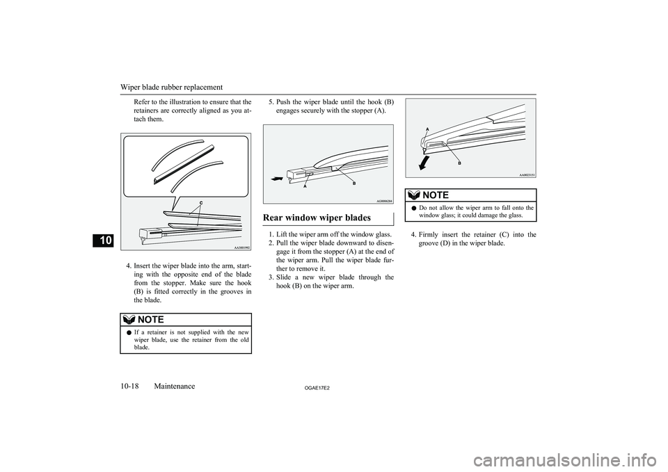
Refer to the illustration to ensure that the
retainers are correctly aligned as you at-
tach them.
4. Insert the wiper blade into the arm, start-
ing with the opposite end of the blade from the stopper. Make sure the hook(B) is fitted correctly in the grooves in
the blade.
NOTEl If a retainer is not supplied with the new
wiper blade, use the retainer from the old
blade.5. Push the wiper blade until the hook (B)
engages securely with the stopper (A).
Rear window wiper blades
1. Lift the wiper arm off the window glass.
2. Pull the wiper blade downward to disen-
gage it from the stopper (A) at the end of
the wiper arm. Pull the wiper blade fur-
ther to remove it.
3. Slide a new wiper blade through the
hook (B) on the wiper arm.
NOTEl Do not allow the wiper arm to fall onto the
window glass; it could damage the glass.
4. Firmly insert the retainer (C) into the
groove (D) in the wiper blade.
Wiper blade rubber replacement
10-18OGAE17E2Maintenance10
Page 419 of 458
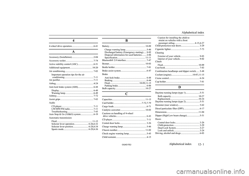
4
4-wheel drive operation.....................................6-41A
Accessory (Installation).....................................2-04
Accessory socket............................................... 7-74
Active stability control (ASC)...........................6-51
Additional equipment...................................... 10-20
Air conditioning................................................ 7-03 Important operation tips for the airconditioning................................................. 7-11
Air purifier.........................................................7-11
Airbag................................................................ 4-24
Anti-lock brake system (ABS).......................... 6-48 Display.......................................................... 6-49
Warning lamp................................................6-49
Ashtray.............................................................. 7-72
Assist grips........................................................ 7-83
Audio CD player...................................................... 7-11
LW/MW/FM radio........................................ 7-11
Troubleshooting............................................ 7-45
Auto Stop & Go (AS&G) system......................6-19
Automatic transmission Fluid............................................................ 11-15
Selector lever operation........................ 6-26,6-32
Selector lever position.......................... 6-28,6-34
Sports mode.......................................... 6-29,6-36
B
Battery............................................................. 10-09
Charge warning lamp.................................... 5-46
Discharged battery (Emergency starting)..... 8-02
Disposal information for used batteries........ 2-06
Specification............................................... 11-11
Bluetooth® 2.0 interface................................... 7-47
Bonnet............................................................. 10-03
Bottle holder...................................................... 7-81
Brake assist system............................................6-47
Brake Anti-lock brake............................................. 6-48
Braking.......................................................... 6-44
Fluid.................................................. 10-09,11-15
Parking brake................................................ 6-06
Bulb capacity................................................... 10-27
C
Capacities........................................................ 11-15
Card holder................................................7-72,7-79
Cargo loads........................................................6-71
Catalytic converter.......................................... 10-03
Cautions on handling of 4-wheel drive vehicles................................................... 6-43
CD player.......................................................... 7-11
Central door locks............................................. 3-26
Charge warning lamp........................................ 5-46
Chassis number............................................... 11-02
Check engine warning lamp.............................. 5-45
Child restraint.................................................... 4-15
Caution for installing the child re- straint on vehicles with a front
passenger airbag.................................. 4-15,4-27
Child-protection rear doors............................... 3-29
Cigarette lighter................................................. 7-73
Cleaning
Exterior of your vehicle................................ 9-03
Interior of your vehicle................................. 9-02
Clutch
Fluid............................................................ 10-09
Coat hook.......................................................... 7-83
Combination headlamps and dipper switch...... 5-48
Coolant (engine)....................................10-07,11-15
Cruise control.................................................... 6-54
Cup holder......................................................... 7-81
D
Daytime running lamps (type 1)........................5-51Bulb capacity.............................................. 10-27
Replacement................................................ 10-34
Daytime running lamps (type 2)........................5-51
Demister (rear window).................................... 5-62 Diesel particulate filter (DPF)........................... 6-17Dimensions...................................................... 11-04
Dipper (High/Low beam change)......................5-51
Doors Central door locks......................................... 3-26Child-protection............................................ 3-29 Dead Lock System........................................ 3-27
Lock and unlock............................................ 3-24
Driving, alcohol and drugs................................ 6-03
Alphabetical index
12- 1
OGAE17E2Alphabetical index
Page 420 of 458
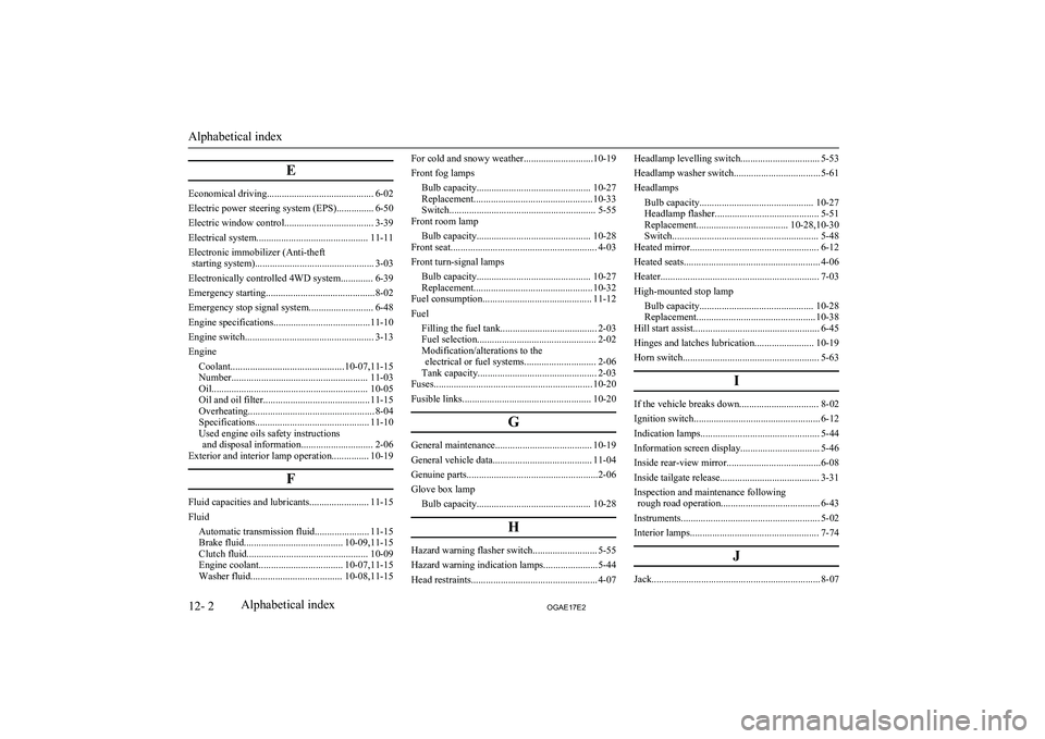
E
Economical driving........................................... 6-02
Electric power steering system (EPS)............... 6-50
Electric window control.................................... 3-39
Electrical system............................................. 11-11
Electronic immobilizer (Anti-theft starting system)................................................ 3-03
Electronically controlled 4WD system............. 6-39
Emergency starting............................................8-02
Emergency stop signal system.......................... 6-48
Engine specifications.......................................11-10
Engine switch.................................................... 3-13
Engine Coolant..............................................10-07,11-15
Number....................................................... 11-03
Oil............................................................... 10-05
Oil and oil filter........................................... 11-15
Overheating................................................... 8-04
Specifications.............................................. 11-10
Used engine oils safety instructions and disposal information............................. 2-06
Exterior and interior lamp operation............... 10-19
F
Fluid capacities and lubricants........................ 11-15
Fluid Automatic transmission fluid...................... 11-15
Brake fluid........................................ 10-09,11-15
Clutch fluid................................................. 10-09
Engine coolant.................................. 10-07,11-15
Washer fluid..................................... 10-08,11-15
For cold and snowy weather............................10-19
Front fog lamps Bulb capacity.............................................. 10-27
Replacement................................................ 10-33
Switch........................................................... 5-55
Front room lamp
Bulb capacity.............................................. 10-28
Front seat........................................................... 4-03
Front turn-signal lamps Bulb capacity.............................................. 10-27
Replacement................................................ 10-32
Fuel consumption............................................ 11-12
Fuel Filling the fuel tank....................................... 2-03
Fuel selection................................................ 2-02
Modification/alterations to the electrical or fuel systems............................. 2-06
Tank capacity................................................ 2-03
Fuses................................................................ 10-20
Fusible links.................................................... 10-20
G
General maintenance....................................... 10-19
General vehicle data........................................ 11-04
Genuine parts.....................................................2-06
Glove box lamp Bulb capacity.............................................. 10-28
H
Hazard warning flasher switch.......................... 5-55
Hazard warning indication lamps......................5-44
Head restraints................................................... 4-07
Headlamp levelling switch................................ 5-53
Headlamp washer switch...................................5-61
Headlamps Bulb capacity.............................................. 10-27
Headlamp flasher.......................................... 5-51 Replacement..................................... 10-28,10-30Switch........................................................... 5-48
Heated mirror.................................................... 6-12
Heated seats....................................................... 4-06
Heater................................................................ 7-03
High-mounted stop lamp Bulb capacity.............................................. 10-28
Replacement................................................ 10-38
Hill start assist................................................... 6-45
Hinges and latches lubrication........................ 10-19
Horn switch....................................................... 5-63
I
If the vehicle breaks down................................ 8-02
Ignition switch................................................... 6-12
Indication lamps................................................ 5-44
Information screen display................................ 5-46
Inside rear-view mirror......................................6-08
Inside tailgate release........................................ 3-31
Inspection and maintenance following rough road operation........................................ 6-43
Instruments........................................................ 5-02
Interior lamps.................................................... 7-74
J
Jack.................................................................... 8-07
Alphabetical index
12- 2 OGAE17E2Alphabetical index