Asc MITSUBISHI ASX 2017 Owner's Manual (in English)
[x] Cancel search | Manufacturer: MITSUBISHI, Model Year: 2017, Model line: ASX, Model: MITSUBISHI ASX 2017Pages: 458, PDF Size: 22.98 MB
Page 4 of 458
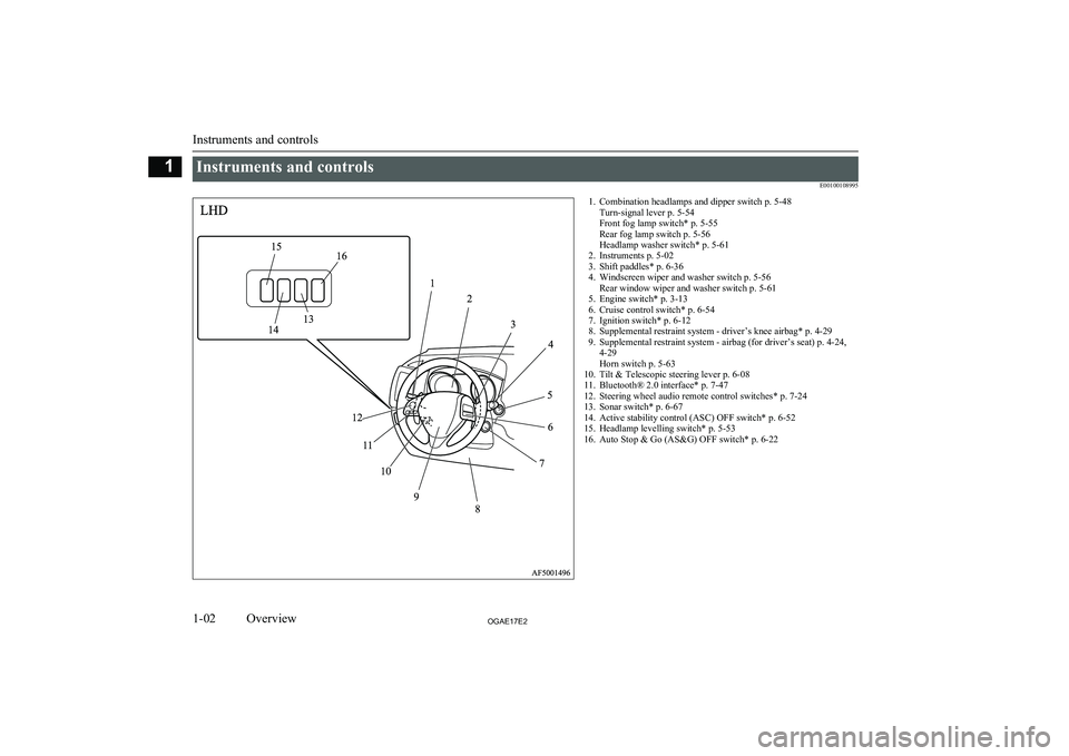
Instruments and controlsE001001089951. Combination headlamps and dipper switch p. 5-48Turn-signal lever p. 5-54
Front fog lamp switch* p. 5-55
Rear fog lamp switch p. 5-56
Headlamp washer switch* p. 5-61
2. Instruments p. 5-02
3. Shift paddles* p. 6-36
4. Windscreen wiper and washer switch p. 5-56 Rear window wiper and washer switch p. 5-61
5. Engine switch* p. 3-13
6. Cruise control switch* p. 6-54
7. Ignition switch* p. 6-12
8. Supplemental restraint system - driver’s knee airbag* p. 4-29
9. Supplemental restraint system - airbag (for driver’s seat) p. 4-24, 4-29
Horn switch p. 5-63
10. Tilt & Telescopic steering lever p. 6-08
11. Bluetooth® 2.0 interface* p. 7-47
12. Steering wheel audio remote control switches* p. 7-24
13. Sonar switch* p. 6-67
14. Active stability control (ASC) OFF switch* p. 6-52
15. Headlamp levelling switch* p. 5-53
16. Auto Stop & Go (AS&G) OFF switch* p. 6-22
Instruments and controls
1-02OGAE17E2Overview11516
13
14 1
2
34
5 6
7
8
9
10
11
12
LHD
Page 5 of 458
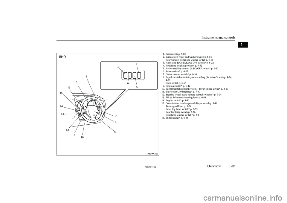
1. Instruments p. 5-02
2. Windscreen wiper and washer switch p. 5-56 Rear window wiper and washer switch p. 5-61
3. Auto Stop & Go (AS&G) OFF switch* p. 6-22
4. Headlamp levelling switch* p. 5-53
5. Active stability control (ASC) OFF switch* p. 6-52
6. Sonar switch* p. 6-67
7. Cruise control switch* p. 6-54
8. Supplemental restraint system - airbag (for driver’s seat) p. 4-24, 4-29
Horn switch p. 5-63
9. Ignition switch* p. 6-12
10. Supplemental restraint system - driver’s knee airbag* p. 4-29
11. Bluetooth® 2.0 interface* p. 7-47
12. Steering wheel audio remote control switches* p. 7-24
13. Tilt & Telescopic steering lever p. 6-08
14. Engine switch* p. 3-13
15. Combination headlamps and dipper switch p. 5-48 Turn-signal lever p. 5-54
Front fog lamp switch* p. 5-55
Rear fog lamp switch p. 5-56
Headlamp washer switch* p. 5-61
16. Shift paddles* p. 6-36
Instruments and controls
1-03OGAE17E2Overview12
1
16
15
14 13
12 11 10 98
7 5
6
3
4
RHD
Page 32 of 458
Refer to “Keyless operation system: Keylessentry system” on page 3-21.
The driver should always carry the keyless operation key. This key is necessary for lock-
ing and unlocking the doors and tailgate,
starting the engine and otherwise operating the vehicle, so before locking and leaving the vehicle, be sure to check that you have the
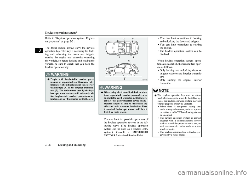
keyless operation key.WARNINGl People with implantable cardiac pace-
makers or implantable cardiovascular-de-
fibrillators should not go near the exterior
transmitters (A) or the interior transmit- ters (B). The radio waves used by the key-
less operation system could adversely af- fect implantable cardiac pacemakers orimplantable cardiovascular-defibrillators.WARNINGl When using electro-medical devices other
than implantable cardiac pacemakers or implantable cardiovascular-defibrillators,
contact the electromedical device manu- facturer ahead of time to determine theaffects of radio waves on the devices. Elec-
tromedical device operations could be af- fected by radio waves.
You can limit the possible operations of
the keyless operation system in the fol-
lowing ways. (The keyless operation system can be used as a keyless entry system.) Consult a MITSUBISHI
MOTORS Authorized Service Point.
• You can limit operations to locking
and unlocking the doors and tailgate.
• You can limit operations to starting
the engine.
• The keyless operation system can be
disabled.
When keyless operation system opera-
tions are modified, the transmitters oper- ate as follows. • Only locking and unlocking doors or
tailgate: exterior and interior transmit- ters.
• Only starting the engine: interior
transmitter.NOTEl The keyless operation key uses an ultra-
weak electromagnetic wave. In the following
cases, the keyless operation system may not
operate properly or may be unstable.
• When there is equipment nearby that
emits strong radio waves, such as: a pow-
er station, a radio/TV broadcasting station or an airport.
• The keyless operation system is carried
together with a communications device such as a cellular phone or radio set, or
with an electronic device such as a per- sonal computer.
• The keyless operation key is touching or
covered by a metal object.
Keyless operation system*
3-08OGAE17E2Locking and unlocking3
Page 108 of 458
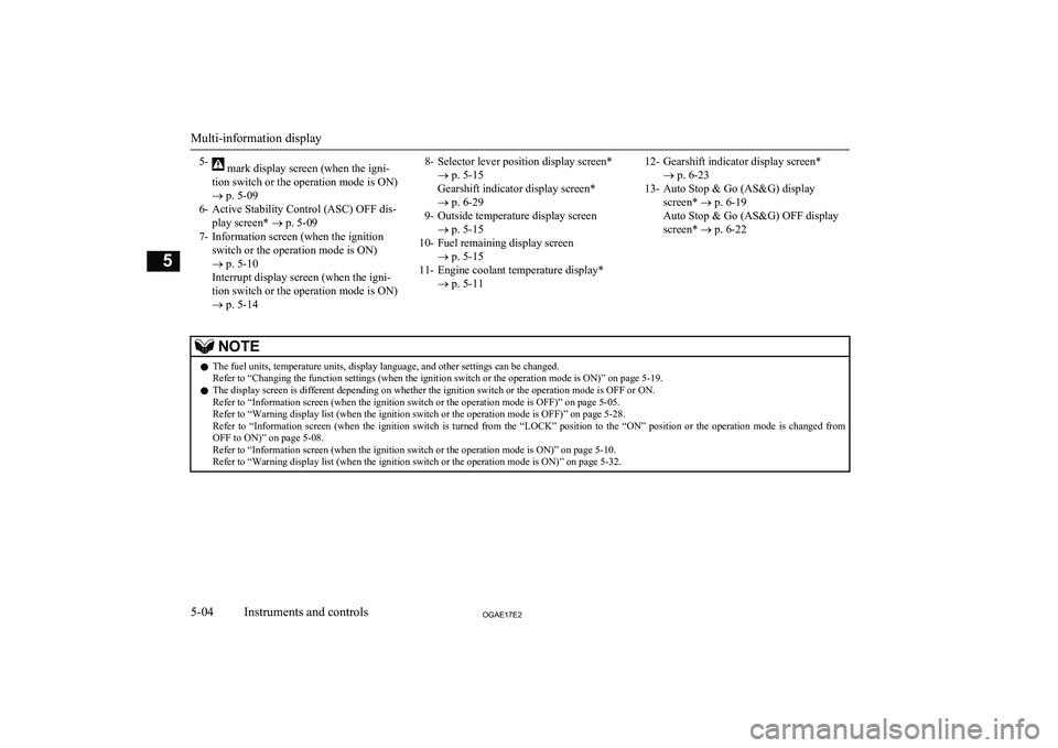
5- mark display screen (when the igni-
tion switch or the operation mode is ON)
® p. 5-09
6- Active Stability Control (ASC) OFF dis- play screen* ® p. 5-09
7- Information screen (when the ignition switch or the operation mode is ON)
® p. 5-10
Interrupt display screen (when the igni-
tion switch or the operation mode is ON)
® p. 5-148- Selector lever position display screen*
® p. 5-15
Gearshift indicator display screen* ® p. 6-29
9- Outside temperature display screen ® p. 5-15
10- Fuel remaining display screen ® p. 5-15
11- Engine coolant temperature display* ® p. 5-1112- Gearshift indicator display screen*
® p. 6-23
13- Auto Stop & Go (AS&G) display screen* ® p. 6-19
Auto Stop & Go (AS&G) OFF display
screen* ® p. 6-22NOTEl The fuel units, temperature units, display language, and other settings can be changed.
Refer to “Changing the function settings (when the ignition switch or the operation mode is ON)” on page 5-19.
l The display screen is different depending on whether the ignition switch or the operation mode is OFF or ON.
Refer to “Information screen (when the ignition switch or the operation mode is OFF)” on page 5-05.
Refer to “Warning display list (when the ignition switch or the operation mode is OFF)” on page 5-28.
Refer to “Information screen (when the ignition switch is turned from the “LOCK” position to the “ON” position or the operation mode is changed from OFF to ON)” on page 5-08.
Refer to “Information screen (when the ignition switch or the operation mode is ON)” on page 5-10.
Refer to “Warning display list (when the ignition switch or the operation mode is ON)” on page 5-32.
Multi-information display
5-04OGAE17E2Instruments and controls5
Page 113 of 458
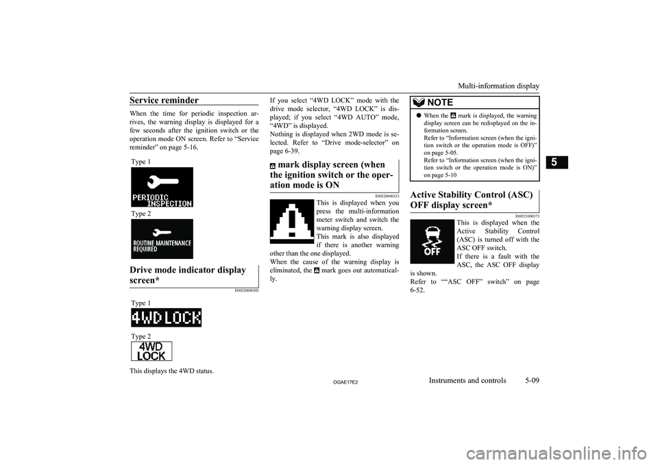
Service reminder
When the time for periodic inspection ar-rives, the warning display is displayed for a
few seconds after the ignition switch or the operation mode ON screen. Refer to “Service
reminder” on page 5-16.
Type 1
Type 2
Drive mode indicator display
screen*
E00520800303
Type 1Type 2
This displays the 4WD status.
If you select “4WD LOCK” mode with the drive mode selector, “4WD LOCK” is dis-played; if you select “4WD AUTO” mode,
“4WD” is displayed.
Nothing is displayed when 2WD mode is se- lected. Refer to “Drive mode-selector” on
page 6-39. mark display screen (when
the ignition switch or the oper- ation mode is ON
E00520900333
This is displayed when you
press the multi-information meter switch and switch the
warning display screen.
This mark is also displayed if there is another warning
other than the one displayed.
When the cause of the warning display is
eliminated, the
mark goes out automatical-
ly.
NOTEl When the mark is displayed, the warning
display screen can be redisplayed on the in- formation screen.
Refer to “Information screen (when the igni-
tion switch or the operation mode is OFF)” on page 5-05.
Refer to “Information screen (when the igni- tion switch or the operation mode is ON)”
on page 5-10Active Stability Control (ASC)
OFF display screen*
E00521000373
This is displayed when the Active Stability Control(ASC) is turned off with the
ASC OFF switch.
If there is a fault with the ASC, the ASC OFF display
is shown.
Refer to ““ASC OFF” switch” on page 6-52.
Multi-information display
5-09OGAE17E2Instruments and controls5
Page 131 of 458
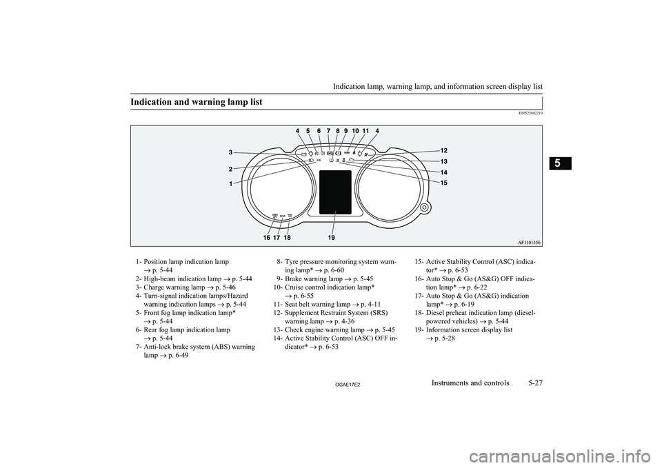
Indication and warning lamp list
E00523802210
1- Position lamp indication lamp® p. 5-44
2- High-beam indication lamp ® p. 5-44
3- Charge warning lamp ® p. 5-46
4- Turn-signal indication lamps/Hazard warning indication lamps ® p. 5-44
5- Front fog lamp indication lamp* ® p. 5-44
6- Rear fog lamp indication lamp ® p. 5-44
7- Anti-lock brake system (ABS) warning lamp ® p. 6-498- Tyre pressure monitoring system warn-
ing lamp* ® p. 6-60
9- Brake warning lamp ® p. 5-45
10- Cruise control indication lamp* ® p. 6-55
11- Seat belt warning lamp ® p. 4-11
12- Supplement Restraint System (SRS) warning lamp ® p. 4-36
13- Check engine warning lamp ® p. 5-45
14- Active Stability Control (ASC) OFF in- dicator* ® p. 6-5315- Active Stability Control (ASC) indica-
tor* ® p. 6-53
16- Auto Stop & Go (AS&G) OFF indica- tion lamp* ® p. 6-22
17- Auto Stop & Go (AS&G) indication lamp* ® p. 6-19
18- Diesel preheat indication lamp (diesel- powered vehicles) ® p. 5-44
19- Information screen display list ® p. 5-28
Indication lamp, warning lamp, and information screen display list
5-27OGAE17E2Instruments and controls5
Page 142 of 458
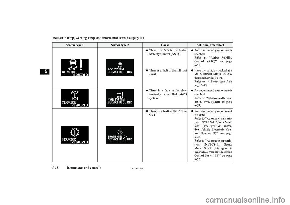
Screen type 1Screen type 2CauseSolution (Reference)lThere is a fault in the Active
Stability Control (ASC).l We recommend you to have it
checked.
Refer to “Active Stability Control (ASC)” on page
6-51.l There is a fault in the hill start
assist.l Have the vehicle checked at a
MITSUBISHI MOTORS Au-
thorized Service Point.
Refer to “Hill start assist” on page 6-45.l There is a fault in the elec-
tronically controlled 4WD
system.l We recommend you to have it
checked.
Refer to “Electronically con- trolled 4WD system” on page
6-39.l There is a fault in the
A/T or
CVT.l We recommend you to have it
checked.
Refer to “Automatic transmis-
sion INVECS-II Sports Mode
6A/T (Intelligent & Innova-
tive Vehicle Electronic Con- trol System II)” on page6-26.
Refer to “Automatic transmis-
sion INVECS-III Sports
Mode 6CVT (Intelligent & Innovative Vehicle Electronic
Control System III)” on page
6-32.
Indication lamp, warning lamp, and information screen display list
5-38OGAE17E2Instruments and controls5
Page 146 of 458
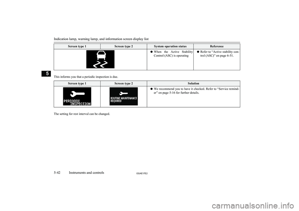
Screen type 1Screen type 2System operation statusReferencelWhen the Active Stability
Control (ASC) is operatingl Refer to “Active stability con-
trol (ASC)” on page 6-51.
This informs you that a periodic inspection is due.
Screen type 1Screen type 2Solutionl We recommend you to have it checked. Refer to
“Service remind-
er” on page 5-16 for further details.
The setting for rest interval can be changed.
Indication lamp, warning lamp, and information screen display list
5-42OGAE17E2Instruments and controls5
Page 169 of 458
Economical driving............................................................................. 6-02
Driving, alcohol and drugs.................................................................. 6-03
Safe driving techniques....................................................................... 6-03
Running-in recommendations............................................................. 6-04 Parking brake...................................................................................... 6-06
Parking................................................................................................ 6-07
Steering wheel height and reach adjustment....................................... 6-08
Inside rear-view mirror....................................................................... 6-08 Outside rear-view mirrors................................................................... 6-10
Ignition switch.....................................................................................6-12 Steering wheel lock............................................................................. 6-13
Starting................................................................................................ 6-14 Diesel particulate filter (DPF)*........................................................... 6-17Turbocharger operation*..................................................................... 6-18Auto Stop & Go (AS&G) system*..................................................... 6-19
Manual transmission*......................................................................... 6-23 Automatic transmission INVECS-II Sports Mode 6A/T (Intelligent & Innovative Vehicle Electronic Control
System II)*......................................................................................6-26
Automatic transmission INVECS-III Sports Mode 6CVT (Intelligent & Innovative Vehicle Electronic Control
System III)*.................................................................................... 6-32
Electronically controlled 4WD system*............................................. 6-39 4-wheel drive operation...................................................................... 6-41
Inspection and maintenance following rough road operation............. 6-43
Cautions on handling of 4-wheel drive vehicles................................. 6-43
Braking................................................................................................ 6-44
Hill start assist*................................................................................... 6-45
Brake assist system............................................................................. 6-47Emergency stop signal system*.......................................................... 6-48
Anti-lock brake system (ABS)............................................................ 6-48
Electric power steering system (EPS)................................................. 6-50 Active stability control (ASC)*.......................................................... 6-51Cruise control*.................................................................................... 6-54
Tyre pressure monitoring system (TPMS)*........................................ 6-59 Reversing sensor system*................................................................... 6-65
Rear-view camera*............................................................................. 6-69 Cargo loads......................................................................................... 6-71Trailer towing......................................................................................6-73Starting and driving
OGAE17E26
Page 214 of 458
CAUTIONlDo not overly rely on the hill start assist to
prevent backwards movement of the vehicle. Under certain circumstances, even when hill
start assist is activated, the vehicle may
move backwards if the brake pedal is not sufficiently depressed, if the vehicle is heav-
ily loaded, or if the road is very steep or slip- pery.
l The hill start assist is not designed to keep
the vehicle stopped in place on uphill slopes for more than 2 seconds.
l When facing uphill, do not rely on using the
hill start assist to maintain a stopped position as an alternative to depressing the brake ped-
al.
Doing so could result in an accident.
l Do not perform the following operation
while the hill start assist is operating.
[Except for vehicles equipped with keyless operation system]
Turn the ignition switch to the “LOCK” or
“ACC” position.
[Vehicles equipped with keyless operation
system]
Put the operation mode in OFF or ACC.
The hill start assist could stop operating, which could result in an accident.To operate
E00628100374
1. Stop the vehicle completely using the
brake pedal.
2. On vehicles equipped with M/T, place
the gearshift lever into the 1 st
position.
On vehicles equipped with A/T, CVT,
place the selector lever into the “D” po- sition.NOTEl When reversing on an uphill slope, place the
gearshift lever or the selector lever into the
“R” position.
3. Release the brake pedal and the hill start
assist will maintain the braking force ap-
plied while stopping for approximately 2 seconds.
4. Depress the accelerator pedal and the
hill start assist gradually will decrease the braking force as the vehicle startsmoving.
NOTEl The hill start assist is activated when all of
the following conditions are met.
• The engine is running.
(The hill start assist will not be activated
while the engine is starting or immediate-
ly after the engine is started.)NOTE• On vehicles equipped with
M/T, the gear-
shift lever is in the following position.
[When starting an uphill slope forwards.]
The gearshift lever is in any position other
than “R”.
(The hill start assist will operate, even if the gearshift lever is in the “N” position.)
[When starting an uphill slope back-
wards.]
The gearshift lever is in the “R” position.
(The hill start assist will not operate when
the gearshift lever is in the “N” position.)
• On vehicles equipped with
A/T, CVT, the
selector lever is in any position other than “P” or “N”.
• The vehicle is completely stationary, with
the brake pedal depressed.
• The parking brake is released.
l The hill start assist will not operate if the ac-
celerator pedal is depressed before the brake pedal is released.
l The hill start assist also operates when re-
versing on an uphill slope.Warning display
E00628200199
If an abnormal condition occurs in the sys-
tem, the following display/indicator will turn
on.
-ASC indicator
Hill start assist*
6-46OGAE17E2Starting and driving6