fuse MITSUBISHI ASX 2018 Owner's Manual (in English)
[x] Cancel search | Manufacturer: MITSUBISHI, Model Year: 2018, Model line: ASX, Model: MITSUBISHI ASX 2018Pages: 514, PDF Size: 34.89 MB
Page 6 of 514
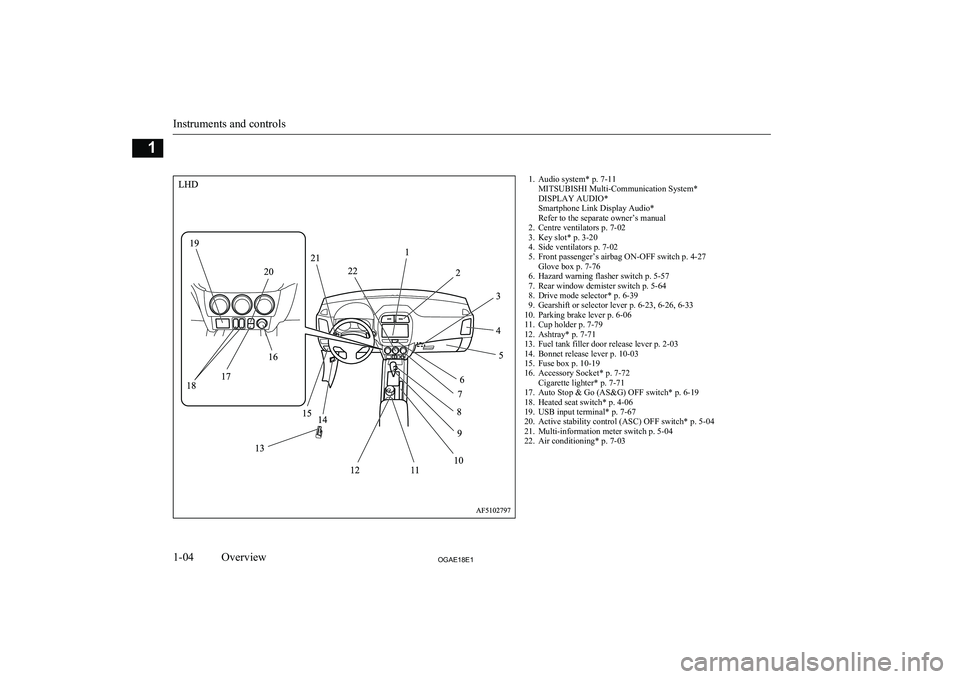
1. Audio system* p. 7-11MITSUBISHI Multi-Communication System*
DISPLAY AUDIO*
Smartphone Link Display Audio*
Refer to the separate owner’s manual
2. Centre ventilators p. 7-02
3. Key slot* p. 3-20
4. Side ventilators p. 7-02
5. Front passenger’s airbag ON-OFF switch p. 4-27 Glove box p. 7-76
6. Hazard warning flasher switch p. 5-57
7. Rear window demister switch p. 5-64
8. Drive mode selector* p. 6-39
9. Gearshift or selector lever p. 6-23, 6-26, 6-33
10. Parking brake lever p. 6-06
11. Cup holder p. 7-79
12. Ashtray* p. 7-71
13. Fuel tank filler door release lever p. 2-03
14. Bonnet release lever p. 10-03
15. Fuse box p. 10-19
16. Accessory Socket* p. 7-72 Cigarette lighter* p. 7-71
17. Auto Stop & Go (AS&G) OFF switch* p. 6-19
18. Heated seat switch* p. 4-06
19. USB input terminal* p. 7-67
20. Active stability control (ASC) OFF switch* p. 5-04
21. Multi-information meter switch p. 5-04
22. Air conditioning* p. 7-03
Instruments and controls
1-04OGAE18E1Overview1
Page 7 of 514
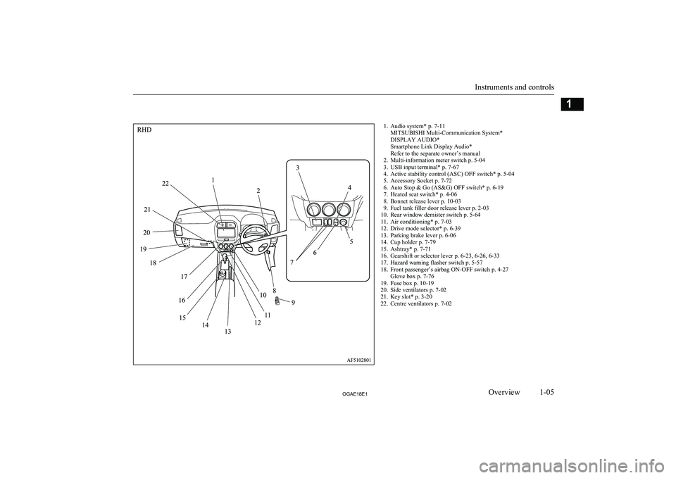
1. Audio system* p. 7-11MITSUBISHI Multi-Communication System*
DISPLAY AUDIO*
Smartphone Link Display Audio*
Refer to the separate owner’s manual
2. Multi-information meter switch p. 5-04
3. USB input terminal* p. 7-67
4. Active stability control (ASC) OFF switch* p. 5-04
5. Accessory Socket p. 7-72
6. Auto Stop & Go (AS&G) OFF switch* p. 6-19
7. Heated seat switch* p. 4-06
8. Bonnet release lever p. 10-03
9. Fuel tank filler door release lever p. 2-03
10. Rear window demister switch p. 5-64
11. Air conditioning* p. 7-03
12. Drive mode selector* p. 6-39
13. Parking brake lever p. 6-06
14. Cup holder p. 7-79
15. Ashtray* p. 7-71
16. Gearshift or selector lever p. 6-23, 6-26, 6-33
17. Hazard warning flasher switch p. 5-57
18. Front passenger’s airbag ON-OFF switch p. 4-27 Glove box p. 7-76
19. Fuse box p. 10-19
20. Side ventilators p. 7-02
21. Key slot* p. 3-20
22. Centre ventilators p. 7-02
Instruments and controls
1-05OGAE18E1Overview1
Page 22 of 514
Even when such parts are officially author-
ized, for example by a “general operators permit” (an appraisal for the part) or throughthe execution of the part in an officially ap-
proved manner of construction, or when a single operation permit following the attach-
ment or installation of such parts, it cannot be deduced from that alone, that the drivingsafety of your vehicle has not been affected.
Consider also that there basically exists no li-
ability on the part of the appraiser or the offi- cial. Maximum safety can only be ensured
with parts recommended, sold and fitted or
installed by a MITSUBISHI MOTORS Au-
thorized Service Point ( MITSUBISHI
MOTORS genuine replacement parts and
MITSUBISHI MOTORS accessories). The
same also pertains to modifications of
MITSUBISHI vehicles with respect to the
production specifications. For safety reasons, do not attempt any modifications other than those that follow the recommendations of a
MITSUBISHI MOTORS Authorized Service
Point.Modification/alterations to
the electrical or fuel systems E00200400368
MITSUBISHI MOTORS CORPORATION
has always manufactured safe, high quality vehicles. In order to maintain this safety and
quality, it is important that any accessory that is to be fitted, or any modifications carried
out which involve the electrical or fuel sys- tems, should be carried out in accordancewith MITSUBISHI guidelines.CAUTIONl If the wires interfere with the vehicle body
or improper installation methods are used(protective fuses not included, etc.), elec-
tronic devices may be adversely affected, re-
sulting in a fire or other accident.Genuine parts
E00200500499
MITSUBISHI MOTORS has gone to great
lengths to bring you a superbly crafted auto-
mobile offering the highest quality and de- pendability.
Use MITSUBISHI MOTORS Genuine Parts,
designed and manufactured to maintain your MITSUBISHI MOTORS automobile at top
performance. MITSUBISHI MOTORS Gen-
uine Parts are identified by this mark and are
available at all MITSUBISHI MOTORS Au-
thorized Service Points.Safety and disposal
information for used engine
oil E00200600155WARNINGlProlonged and repeated contact may
cause serious skin disorders, including
dermatitis and cancer.
l Avoid contact with the skin as far as pos-
sible and wash thoroughly after any con- tact.
l Keep used engine oils out of reach of chil-
dren.
Modification/alterations to the electrical or fuel systems
2-06OGAE18E1General information2
Page 67 of 514
Safety mechanism (driver’sdoor window only)
E00302501895
If a hand or head is trapped in the closing
window, it will lower automatically.
Nonetheless, make sure that nobody puts
their head or hand out of the window when closing the driver’s door window.
The lowered window will become operation-
al after a few seconds.
WARNINGl If the battery terminals are disconnected
or the fuse for electric window is replaced,
the safety mechanism will be cancelled.
If a hand or head got trapped, a serious injury could result.CAUTIONl The safety mechanism is cancelled just be-
fore the window is fully closed. This allows the window to close completely. Therefore be especially careful that no fingers are trap-
ped in the window.
l The safety mechanism is deactivated while
the switch is pulled up. Therefore be espe-
cially careful that fingers are not trapped in the door window opening.NOTEl The safety mechanism can be activated if the
driving conditions or other circumstancescause the driver’s door window to be subjec- ted to a physical shock similar to that caused
by a trapped hand or head.
l If the battery terminals are disconnected or
the fuse for electric window is replaced, the
safety mechanism will be cancelled and the door window will not automatically open/ close completely.
If the window is open, repeatedly raise the
driver’s door window switch until the win-
dow has been fully closed.
Following this, release the switch, raise the switch once again and hold it in this condi- tion for at least 1 second, then release it.
You should now be able to operate the driv- er’s door window in the normal fashion.Sunshade*
E00302801407WARNINGlBefore operating the sunshade, make sure
that nothing can get trapped (head, hand,
finger, etc.).
l Never leave the vehicle without removing
the key.
l Never leave a child (or other person who
might not be capable of safe operation of the sunshade switch) in the vehicle alone.WARNINGl Do not bring your head, hand, finger, etc.
near the opening edge of the sunshade re-
ceptacle while the vehicle is in motion.
It may cause injury to your head, hand, finger, etc. in the event of sudden braking.CAUTIONl Do not place heavy luggage on the panoram-
ic glass roof. Doing so could damage the glass roof.
l Do not hang heavy luggage from, allow a
person to hang onto, or apply any other strong force to the opening of the sunshade receptacle or the parts between the ceiling
and the sunshade opening on either side. Do- ing so could damage the sunshade.NOTEl Release the switch as soon as the sunshade
reaches the fully open or fully closed posi-
tion.
l If the sunshade does not operate when the
sunshade switch is operated, release the
switch and check whether something is trap- ped by the sunshade. If nothing is trapped,
we recommend you to have the sunshade checked.
l Operating the sunshade repeatedly with the
engine stationary will run down the battery.
Operate the sunshade while the engine is running.
Sunshade*
3-41OGAE18E1Locking and unlocking3
Page 201 of 514
WARNINGlThis position can be used for maximum
engine braking.
Be very careful not to shift into “L” (Low) suddenly.
Sudden engine braking may cause the
tyres to skid.
Select this position according to the road conditions and vehicle speed.Sports mode
E00603902809
While the vehicle is stopped or being driven
with the selector lever in the “D” (DRIVE) or
“L” (LOW) position, sports mode can be se- lected by pulling one of the shift paddles to-wards you.
In sports mode, rapid shifting is possible sim-
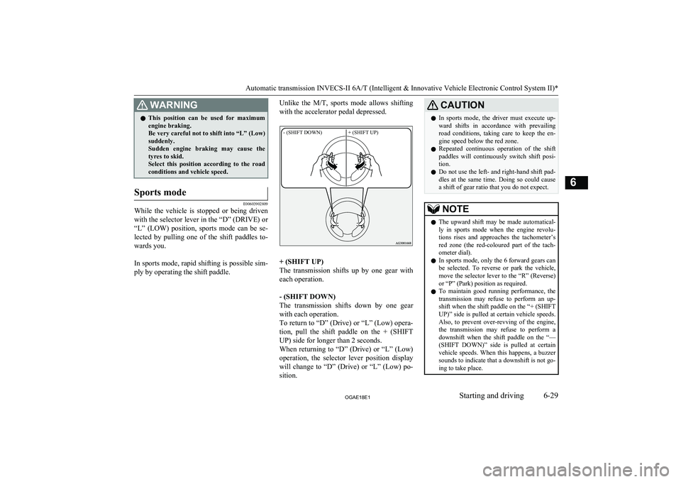
ply by operating the shift paddle.
Unlike the M/T, sports mode allows shifting
with the accelerator pedal depressed.- (SHIFT DOWN)+ (SHIFT UP)
+ (SHIFT UP)
The transmission shifts up by one gear with
each operation.
- (SHIFT DOWN)
The transmission shifts down by one gear
with each operation.
To return to “D” (Drive) or “L” (Low) opera- tion, pull the shift paddle on the + (SHIFT UP) side for longer than 2 seconds.
When returning to “D” (Drive) or “L” (Low)
operation, the selector lever position display will change to “D” (Drive) or “L” (Low) po-sition.
CAUTIONl In sports mode, the driver must execute up-
ward shifts in accordance with prevailingroad conditions, taking care to keep the en-
gine speed below the red zone.
l Repeated continuous operation of the shift
paddles will continuously switch shift posi-
tion.
l Do not use the left- and right-hand shift pad-
dles at the same time. Doing so could cause a shift of gear ratio that you do not expect.NOTEl The upward shift may be made automatical-
ly in sports mode when the engine revolu-
tions rises and approaches the tachometer’s
red zone (the red-coloured part of the tach- ometer dial).
l In sports mode, only the
6 forward gears can
be selected. To reverse or park the vehicle, move the selector lever to the “R” (Reverse)
or “P” (Park) position as required.
l To maintain good running performance, the
transmission may refuse to perform an up- shift when the shift paddle on the “+ (SHIFTUP)” side is pulled at certain vehicle speeds.
Also, to prevent over-revving of the engine,
the transmission may refuse to perform a downshift when the shift paddle on the “—
(SHIFT DOWN)” side is pulled at certain vehicle speeds. When this happens, a buzzer
sounds to indicate that a downshift is not go- ing to take place.
Automatic transmission INVECS-II 6A/T (Intelligent & Innovative Vehicle Electronic Control System II)*
6-29OGAE18E1Starting and driving6
Page 208 of 514
“Ds” DOWNSHIFT & SPOR-TY DRIVING (except for vehi- cles equipped with shift pad-
dles)
Use when engine braking is needed, or for
high-power sport drive.
“L” LOW
This position is for driving up very steep hills and for engine braking at low speeds when
driving down steep hills.
WARNINGl This position can be used for maximum
engine braking.
Be very careful not to shift into “L” (Low) suddenly.
Sudden engine braking may cause the
tyres to skid.
Select this position according to the road conditions and vehicle speed.Sports mode (For vehicles
equipped with shift paddles)
E00602501494
While the vehicle is stopped or being driven with the selector lever in the “D” (DRIVE)
position, sports mode can be selected by pull-
ing one of the shift paddles towards you.
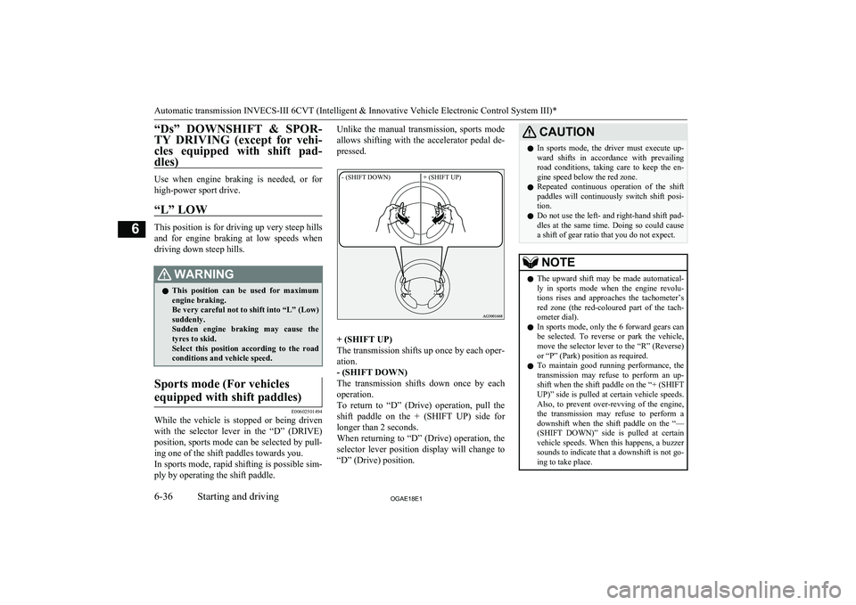
In sports mode, rapid shifting is possible sim-
ply by operating the shift paddle.
Unlike the manual transmission, sports mode
allows shifting with the accelerator pedal de-
pressed.- (SHIFT DOWN)+ (SHIFT UP)
+ (SHIFT UP)
The transmission shifts up once by each oper-
ation.
- (SHIFT DOWN)
The transmission shifts down once by each
operation.
To return to “D” (Drive) operation, pull the
shift paddle on the + (SHIFT UP) side for longer than 2 seconds.
When returning to “D” (Drive) operation, the
selector lever position display will change to “D” (Drive) position.
CAUTIONl In sports mode, the driver must execute up-
ward shifts in accordance with prevailingroad conditions, taking care to keep the en-
gine speed below the red zone.
l Repeated continuous operation of the shift
paddles will continuously switch shift posi-
tion.
l Do not use the left- and right-hand shift pad-
dles at the same time. Doing so could cause a shift of gear ratio that you do not expect.NOTEl The upward shift may be made automatical-
ly in sports mode when the engine revolu-
tions rises and approaches the tachometer’s
red zone (the red-coloured part of the tach- ometer dial).
l In sports mode, only the 6 forward gears can
be selected. To reverse or park the vehicle, move the selector lever to the “R” (Reverse)
or “P” (Park) position as required.
l To maintain good running performance, the
transmission may refuse to perform an up- shift when the shift paddle on the “+ (SHIFTUP)” side is pulled at certain vehicle speeds.
Also, to prevent over-revving of the engine,
the transmission may refuse to perform a downshift when the shift paddle on the “—
(SHIFT DOWN)” side is pulled at certain vehicle speeds. When this happens, a buzzer
sounds to indicate that a downshift is not go- ing to take place.
Automatic transmission INVECS-III 6CVT (Intelligent & Innovative Vehicle Electronic Control System III)*
6-36OGAE18E1Starting and driving6
Page 308 of 514
PICK-UP button
lPress this button when an incoming call
is received to answer the telephone.
l When another call is received during a
call, press this button to put the first call- er on hold and talk to the new caller. • In such circumstances, you can press
the button briefly to switch between
callers. You will switch to the first
caller and the other caller will be put on hold.
• To establish a three-way call in such
situations, press the SPEECH button
to enter voice recognition mode and
then say “Join calls”.
HANG-UP button
l Press this button when an incoming call
is received to refuse the call.
l Press this button during a call to end the
current call.
When another call is on hold, you will
switch to that call.
l If this button is pressed in the voice rec-
ognition mode, the voice recognition
mode will be deactivated.
NOTEl When you press the SPEECH button to enter
voice recognition mode with a cellular
phone paired to the system, current informa- tion on the cellular phone, such as “remain- ing battery life,” “signal strength” or “roam-
ing,” will be displayed on the audio dis-
play.*
*: Some cellular phones will not send this
information to the Bluetooth ®
2.0 interface.
l Call waiting and three-way calls can be used
by the Bluetooth ®
2.0 interface, only if it is
possible to use those services with your cel- lular phone.
Microphone
Your voice will be recognized by a micro-
phone in the overhead console, allowing you to make hands-free calls with voice com-
mands.
NOTEl If a cellular phone is within close proximity
of the microphone, it may distort the soundquality. In this case, place the cellular phone as far as possible from the microphone.Voice recognition function
E00727301670
The Bluetooth ®
2.0 interface is equipped
with a voice recognition function.
Simply say voice commands and you can
perform various operations and make or re- ceive hands-free calls.
With the Bluetooth ®
2.0 interface, voice rec-
ognition is possible for English, French,
Spanish, Italian, German, Dutch, Portuguese and Russian. The factory setting is “English” or “Russian.”NOTEl If the voice command that you say differs
from the predefined command or cannot be recognised due to ambient noise or some
other reason, the Bluetooth ®
2.0 interface
will ask you for the voice command again up
to 3 times.
l For best performance and further reduction
of ambient noise, close the vehicle windows, lower the blower speed and refrain from conversation with your passengers while en-
gaging the voice recognition function.
l Some voice commands have alternative
commands.
l Depending on the selected language, some
functions may not be available.
Selecting the Language
1. Press the SPEECH button.
2. Say “Setup”.
3. Say “Language.”
Bluetooth ®
2.0 interface*
7-48OGAE18E1For pleasant driving7
Page 375 of 514
Service precautions........................................................................... 10-02
Catalytic converter............................................................................ 10-03
Bonnet............................................................................................... 10-03
Engine oil.......................................................................................... 10-05 Engine coolant...................................................................................10-07
Washer fluid...................................................................................... 10-08
Brake fluid/Clutch fluid*.................................................................. 10-09
Battery............................................................................................... 10-09 Tyres..................................................................................................10-13Wiper blade rubber replacement....................................................... 10-17
General maintenance......................................................................... 10-18
For cold and snowy weather............................................................. 10-19
Fusible links...................................................................................... 10-19
Fuses..................................................................................................10-19
Replacement of lamp bulbs............................................................... 10-26Maintenance
OGAE18E110
Page 392 of 514
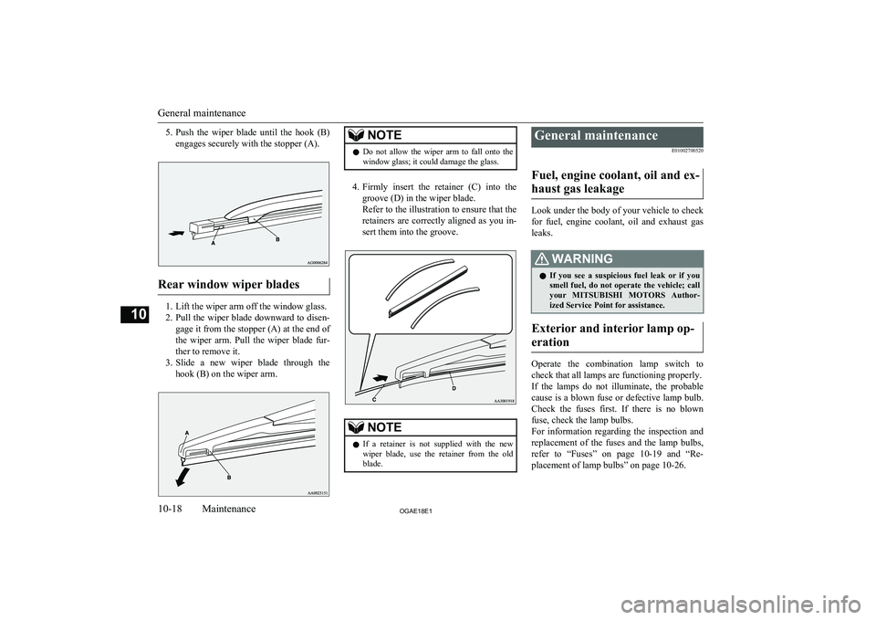
5.Push the wiper blade until the hook (B)
engages securely with the stopper (A).
Rear window wiper blades
1. Lift the wiper arm off the window glass.
2. Pull the wiper blade downward to disen-
gage it from the stopper (A) at the end of
the wiper arm. Pull the wiper blade fur-
ther to remove it.
3. Slide a new wiper blade through the
hook (B) on the wiper arm.
NOTEl Do not allow the wiper arm to fall onto the
window glass; it could damage the glass.
4. Firmly insert the retainer (C) into the
groove (D) in the wiper blade.
Refer to the illustration to ensure that the retainers are correctly aligned as you in-
sert them into the groove.
NOTEl If a retainer is not supplied with the new
wiper blade, use the retainer from the old
blade.General maintenance
E01002700520
Fuel, engine coolant, oil and ex- haust gas leakage
Look under the body of your vehicle to check
for fuel, engine coolant, oil and exhaust gas
leaks.
WARNINGl If you see a suspicious fuel leak or if you
smell fuel, do not operate the vehicle; call
your MITSUBISHI MOTORS Author-
ized Service Point for assistance.
Exterior and interior lamp op-
eration
Operate the combination lamp switch to
check that all lamps are functioning properly.
If the lamps do not illuminate, the probable cause is a blown fuse or defective lamp bulb.
Check the fuses first. If there is no blown
fuse, check the lamp bulbs.
For information regarding the inspection and
replacement of the fuses and the lamp bulbs, refer to “Fuses” on page 10-19 and “Re-
placement of lamp bulbs” on page 10-26.
General maintenance
10-18OGAE18E1Maintenance10
Page 393 of 514
If the fuses and bulbs are all OK, we recom-
mend you to have your vehicle checked and repaired.
Meter, gauge and indicator/warning lamps operation
Start the engine and check the operation of all instruments, gauges and indication andwarning lamps.
If there is anything wrong, we recommend
you to have your vehicle inspected.
Hinges and latches lubrication
Check all latches and hinges, and, if necessa- ry, have them lubricated.
For cold and snowy weather
E01002800361
Ventilation slots
The ventilation slots in front of the wind-
screen should be kept clear of leaves or brushed clear after heavy snowfall, so that
the operation of the heating and ventilation
systems will not be impaired.
Weatherstripping
To prevent freezing of the weatherstripping
on the doors, bonnet, etc., they should be treated with silicone grease.
Additional equipment
It is a good idea to carry a shovel or a short-
handled spade in the vehicle during the win- ter so that you can clear away snow if you get stranded. A small hand-brush for sweeping
snow off the vehicle and a plastic scraper for the windscreen and rear window are also use-ful.
Fusible links
E01002900564
The fusible links will melt to prevent a fire if
a large current attempts to flow through cer- tain electrical systems.
In case of a melted fusible link, we recom- mend you to have your vehicle inspected.
For the fusible links, please refer to “Fuse
load capacity” on page 10-21.
WARNINGl Fusible links must not be replaced by any
other device. Failing to fit the correct fusi-
ble link may result in fire in the vehicle,
property destruction and serious or fatal injuries at any time.Fuses
E01003002250
Fuse block location
To prevent damage to the electrical systemdue to shortcircuiting or overloading, each in-
dividual circuit is provided with a fuse.
There are fuse blocks in the passenger com-
partment and in the engine compartment.
For cold and snowy weather
10-19OGAE18E1Maintenance10