alternator MITSUBISHI COLT 2006 Service Repair Manual
[x] Cancel search | Manufacturer: MITSUBISHI, Model Year: 2006, Model line: COLT, Model: MITSUBISHI COLT 2006Pages: 364, PDF Size: 11.65 MB
Page 32 of 364

A/C-ECU
HEATER, AIR CONDITIONER AND VENTILATION55-8
A/C-ECU
M2551001200179
CONTROL SYSTEM
The manual and automatic A/Cs have the following
control functions.
ControlManual A/CAutomatic A/C
Automatic wind temperature change controlApplicableApplicable
Automatic outside/inside air selection controlApplicableApplicable
Idle-up controlApplicableApplicable
Cooling fun load controlApplicableApplicable
Cooling controlApplicableApplicable
Detection control for refrigerant leaksApplicableApplicable
MAX A/C controlNot applicableApplicable
Estimation control for compressor torqueApplicableApplicable
Defroster linked controlNot applicableApplicable
AUTOMATIC CHANGE CONTROL OF
BLOW WIND TEMPERATURE
(COMPRESSOR
ENERGY-CONSERVATION CONTROL)
Optimum ON/OFF control of the compressor is
achieved according to the outside/inside air mode,
air temperature (air temperature sensor), and insula
-
tion.
OUTSIDE/INSIDE AIR AUTO SWITCHING
CONTROL
When the A/C is turned on in high ambient tempera-
ture, the recirculation function is automatically acti-
vated to cool down the passenger compartment and
improve fuel consumption.
COOLING FUN LOAD CONTROL
Depending on the A/C load, the cooling fan cycle
time is controlled and the exterior noise in the inter
-
mediary stage is decreased. Also, the load of the
alternator is decreased to improve the fuel economy.
COOLING CONTROL
If air temperature is high, the CVT rotates at a high
speed to prevent deterioration in cooling perform
-
ance.
DETECTION CONTROL FOR
REFRIGERANT LEAKS
When it is judged from the air temperature (air tem-
perature sensor) and the refrigerant pressure (A/C
pressure sensor) that the refrigerant amount is the
specified value or less, or the refrigerant pressure is
abnormal, the compressor is forced to be cut off to
protect the A/C system.
MAX A/C CONTROL
When MAX COOL position is set, automatically the
mode is changed to the inside air mode before the
A/C is turned ON, thereby facilitating the operation
for obtaining maximum cooling performance.
ESTIMATION CONTROL FOR
COMPRESSOR TORQUE
Communication between the engine⋅CVT-ECU and
A/C-ECU is made to control the engine according to
the compressor torque for higher drivability and
reduction in fuel consumption.
FORCIBLE DEFROSTER CONTROL
When the defroster vents are selected, the A/C is
automatically turned ON. At this time, the out
-
side/inside air selection damper is operated to the
fresh-air position to defrost the windshield glass
quickly.
Page 97 of 364

GENERAL INFORMATION
MULTIPOINT FUEL INJECTION (MPI) <4A9>13A-3
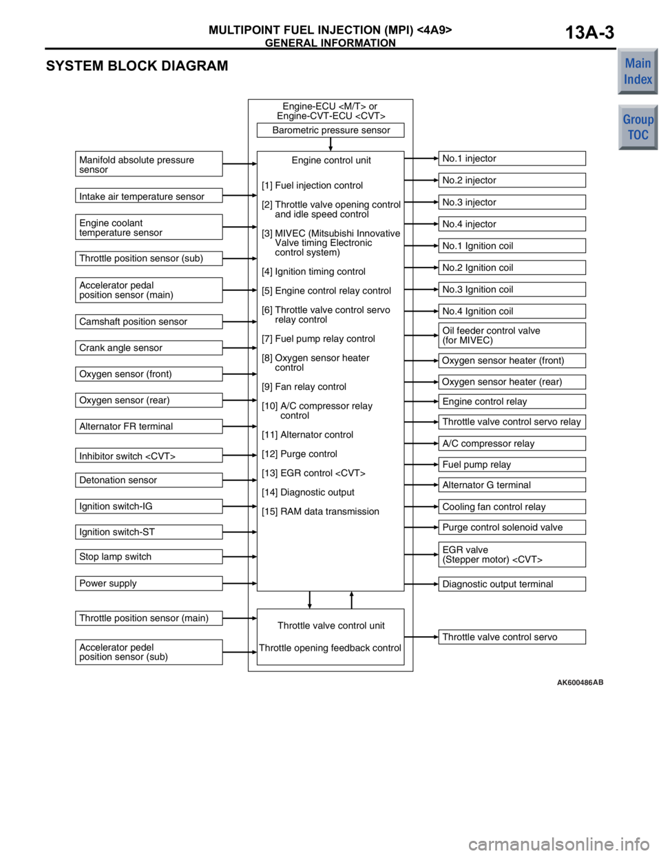
SYSTEM BLOCK DIAGRAM
AK600486
Barometric pressure sensorThrottle valve control servo
Manifold absolute pressure
sensor
Engine coolant
temperature sensor
No.1 injector
No.2 injector
No.3 injector
No.4 injector
No.1 Ignition coil
No.2 Ignition coil
No.3 Ignition coil
No.4 Ignition coil
Engine control relay
Throttle valve control servo relay
A/C compressor relay
Fuel pump relay
Alternator G terminal
Cooling fan control relay
Purge control solenoid valve
Diagnostic output terminal
Intake air temperature sensor
Accelerator pedal
position sensor (main) Throttle position sensor (sub)
Camshaft position sensor
Crank angle sensor
Oxygen sensor (front)
Oxygen sensor (rear)
Alternator FR terminal
Inhibitor switch
Detonation sensor
Ignition switch-IG
Ignition switch-ST
Stop lamp switch
Power supply
Accelerator pedel
position sensor (sub) Throttle position sensor (main)
Throttle valve control unitEngine control unit
Engine-ECU
Engine-CVT-ECU
Throttle opening feedback control Oxygen sensor heater (front)
Oxygen sensor heater (rear)
[1] Fuel injection control
[2] Throttle valve opening control
and idle speed control
[3] MIVEC (Mitsubishi Innovative
Valve timing Electronic
control system)
[4] Ignition timing control
[5] Engine control relay control
[6] Throttle valve control servo
relay control
[7] Fuel pump relay control
[8] Oxygen sensor heater
control
[9] Fan relay control
[10] A/C compressor relay
control
[11] Alternator control
[12] Purge control
[13] EGR control
[14] Diagnostic output
[15] RAM data transmission
Oil feeder control valve
(for MIVEC)
EGR valve
(Stepper motor)
AB
Page 98 of 364

GENERAL INFORMATION
MULTIPOINT FUEL INJECTION (MPI) <4A9>13A-4
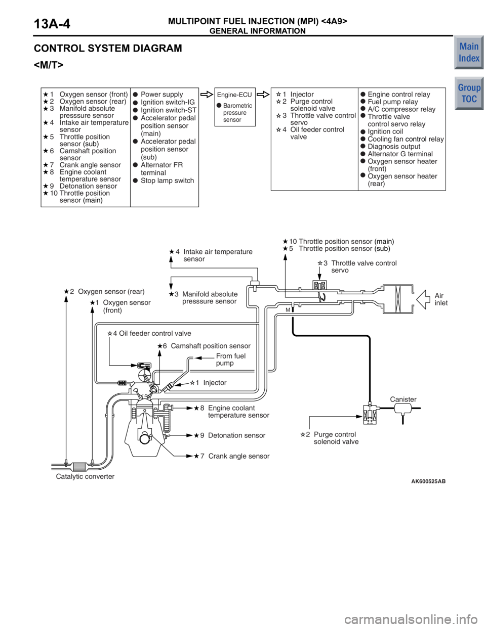
CONTROL SYSTEM DIAGRAM
AK600525
1 Oxygen sensor
(front)4 Intake air temperature
sensor
3 Manifold absolute
presssure sensor
2 Oxygen sensor (rear) 3 Throttle valve control
servo
10 Throttle position sensor
(main)
2 Purge control
solenoid valve
8 Engine coolant
temperature sensor
9 Detonation sensor
7 Crank angle sensor
6 Camshaft position sensor
4 Oil feeder control valve
1 Injector
AB
M
1 Oxygen sensor (front)
2 Oxygen sensor (rear)
3 Manifold absolute
presssure sensor
4 Intake air temperature
sensor
5 Throttle position
sensor
(sub)
6 Camshaft position
sensor
7 Crank angle sensor
8 Engine coolant
temperature sensor
9 Detonation sensor
10 Throttle position
sensor (main) 1 Injector
2 Purge control
solenoid valve
3 Throttle valve control
servo
4 Oil feeder control
valve
Power supply
Ignition switch-IG
Ignition switch-ST
Accelerator pedal
position sensor
(main)
Accelerator pedal
position sensor
(sub)
Alternator FR
terminal
Stop lamp switchEngine-ECUEngine control relay
Fuel pump relay
A/C compressor relay
Throttle valve
control servo relay
Ignition coil
Cooling fan
control relay
Diagnosis output
Alternator G terminal
Oxygen sensor heater
(front)
Oxygen sensor heater
(rear)
Canister Air
inlet
Catalytic converter From fuel
pump
5 Throttle position sensor
(sub)
Barometric
pressure
sensor
Page 99 of 364

GENERAL INFORMATION
MULTIPOINT FUEL INJECTION (MPI) <4A9>13A-5
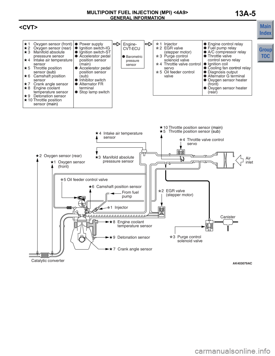
AK403079
1 Oxygen sensor
(front)4 Intake air temperature
sensor
3 Manifold absolute
presssure sensor
2 Oxygen sensor (rear) 4 Throttle valve control
servo
10 Throttle position sensor
(main)
2 EGR valve
(stepper motor) 3 Purge control
solenoid valve
8 Engine coolant
temperature sensor
9 Detonation sensor
7 Crank angle sensor
6 Camshaft position sensor
5 Oil feeder control valve
1 Injector
AC
1 Oxygen sensor (front)
2 Oxygen sensor (rear)
3 Manifold absolute
presssure sensor
4 Intake air temperature
sensor
5 Throttle position
sensor (sub)
6 Camshaft position
sensor
7 Crank angle sensor
8 Engine coolant
temperature sensor
9 Detonation sensor
10 Throttle position
sensor (main) 1 Injector
2 EGR valve
(stepper motor)
3 Purge control
solenoid valve
4 Throttle valve control
servo
5 Oil feeder control
valve
Power supply
Ignition switch-IG
Ignition switch-ST
Accelerator pedal
position sensor
(main)
Accelerator pedal
position sensor
(sub)
Inhibitor switch
Alternator FR
terminal
Stop lamp switchEngine-
CVT-ECUEngine control relay
Fuel pump relay
A/C compressor relay
Throttle valve
control servo relay
Ignition coil
Cooling fan
control relay
Diagnosis output
Alternator G terminal
Oxygen sensor heater
(front)
Oxygen sensor heater
(rear)
Canister Air
inlet
Catalytic converter From fuel
pump
5 Throttle position sensor
(sub)
Barometric
pressure
sensor
Page 101 of 364

GENERAL INFORMATION
MULTIPOINT FUEL INJECTION (MPI) <4A9>13A-7
Throttle position sensor
and inputs it into the engine-ECU
engine-CVT-ECU
is output by this sensor, the engine-ECU
engine-CVT-ECU
feedback control.
Accelerator pedal position sensor
and inputs it into the engine-ECU
engine-CVT-ECU
is output by this sensor, which determines the
accelerator position (and the intention of the driver),
the engine-ECU
effects appropriate fuel injection and throttle valve
position controls.
Camshaft position sensorThis sensor detects the top-dead-center (TDC) of the
compression stroke of each cylinder.
Crank angle sensorThis sensor detects the crank angle and inputs it into
the engine-ECU
The engine-ECU
effects injector control and other controls in
accordance with the signals received from this
sensor.
Detonation sensorThis sensor, which contains a piezoelectric element,
detects the vibration of the cylinder block that results
from knocking. The engine-ECU
engine-CVT-ECU
of the engine from these vibrations, in order to retard
the ignition timing in accordance with the strength of
the knocks.
Alternator FR terminalThis terminal is used for detecting the duty cycle ratio
that energizes the alternator field coil.
Inhibitor switch
into the engine-CVT-ECU to determine whether the
shift lever is in the neutral position.
Stop lamp switchThis is a contact point type switch that detects how
the brake pedal is depressed.
Actuators
Engine control relayThis relay turns ON and OFF the engine-ECU
or engine-CVT-ECU
Throttle valve control servo relayThis relay turns ON and OFF the actuation power
circuit for the throttle valve control servo in the
engine-ECU
InjectorThe injectors inject fuel in accordance with the
injection signals received from the engine-ECU
Ignition coil (with power transistor)Applies ignition coil primary current intermittently in
accordance with the ignition signals received from
the engine-ECU
in order to generate high voltage for ignition.
Name Function
Page 102 of 364

GENERAL INFORMATION
MULTIPOINT FUEL INJECTION (MPI) <4A9>13A-8
Fuel pump relayControls the power supplied to the fuel pump in
accordance with the signals received from the
engine-ECU
A/C compressor relayControls the operation of the A/C compressor in
accordance with the signals received from the
engine-ECU
Purge control solenoid valveControls the flow rate of the purge air introduced into
the inlet manifold in accordance with the signals
received from the engine-ECU
engine-CVT-ECU
EGR valve (stepper motor)
signals received from the engine-CVT-ECU.
Alternator G terminalControls the amount of current generated by the
alternator in accordance with the signals received
from the engine-ECU
Cooling fan control relayControls the rotation of cooling the fan in accordance
with the signals received from the engine-ECU
Throttle valve control servoControls the throttle valve position in accordance with
the signals received from the engine-ECU
engine-CVT-ECU
Oil feeder control valveThe oil feeder control valve, which is actuated by the
signals received from the engine-ECU
engine-CVT-ECU
Oxygen sensor heater
in accordance with the signals received from the
engine-ECU
Name Function
Page 110 of 364

DIAGNOSIS SYSTEM
MULTIPOINT FUEL INJECTION (MPI) <4A9>13A-16
P0606Microcomputer malfunctionAbnormality in engine-ECU
or engine-CVT-ECU
P0622Alternator FR terminal systemOpen circuit or short-circuit in
system-related circuits−
P0638*Throttle valve control servo circuit
range/performance problemAbnormal throttle valve control
servoON
P0642*Throttle position sensor power
supplyAbnormality in engine-ECU
or engine-CVT-ECU
P0657*Throttle valve control servo relay
circuit malfunctionOpen circuit or short-circuit in
sensor-related circuitsON
P1021Oil feeder control valve systemOpen circuit or short-circuit in
solenoid valve-related circuitsON
P1602*Communication malfunction
(between engine-ECU
engine-CVT-ECU
processor and system LSI)Abnormality in engine-ECU
or engine-CVT-ECU
P1603*Battery backup circuit malfunctionOpen circuit or short-circuit in
system-related circuitsON
P2100*Throttle valve control servo circuit
(open)Open circuit in throttle valve control
servo-related circuitON
P2101*Throttle valve control servo
magneto malfunctionShort-circuit in system-related
circuitsON
P2108*Throttle valve control servo
processor malfunctionAbnormality in engine-ECU
or engine-CVT-ECU
P2122*Accelerator pedal position sensor
(main) circuit low inputOpen circuit or short-circuit in
sensor-related circuitsON
P2123*Accelerator pedal position sensor
(main) circuit high inputOpen circuit in sensor-related
circuitsON
P2127*Accelerator pedal position sensor
(sub) circuit low inputOpen circuit or short-circuit in
sensor-related circuitsON
P2128*Accelerator pedal position sensor
(sub) circuit high inputOpen circuit in sensor-related
circuitsON
P2135*Throttle position sensor (main and
sub) range/performance problemAbnormal sensor outputON
P2138*Accelerator pedal position sensor
(main and sub) range/performance
problemAbnormal sensor outputON
P2226Barometric pressure sensor
systemAbnormality in engine-ECU
or engine-CVT-ECU
U1073Bus offAbnormality in CAN bus line−
U1102ABS-ECU time-outAbnormality in CAN bus line−
U1106EPS-ECU time-outAbnormality in CAN bus line−
U1108Combination meter time-outAbnormality in CAN bus lineON
U 111 0A/C-ECU time-outAbnormality in CAN bus line−
Code No. Diagnosis item Main diagnosis contents Engine
warning lamp
Page 113 of 364

DIAGNOSIS SYSTEM
MULTIPOINT FUEL INJECTION (MPI) <4A9>13A-19
Engine-ECU
•Items useful for grasping the engine control con-
dition by the engine-ECU
engine-CVT-ECU
monitor item section.
•Values of these monitor items vary greatly
depending on marginal difference of measure
-
ment conditions, difference of the environment,
aged deterioration of vehicles and so on, and it is
difficult to show the precise specification values.
Therefore, check conditi ons, display range and
movement of values are described.
Item No.Inspection itemDisplay range, numerical value
5AAir-fuel ratio learning value of B zone (Low
speed load)−25 to 25%
5BIdle speed control position learned value−128 to 127STEP
5CIdle speed control position learned value (A/C
load)−128 to 127STEP
6AKnock retardRetards in response to accelerator opening
6BLearned knock retard0 − 100%
6CTarget idle speedChanges in response to engine coolant
temperature
9BAir-fuel ratio learning value of A zone (Low
load)−25 to 25%
9DAir-fuel ratio feedback integration−25 to 25%
B2Alternator G terminal dutyIncreases
B3Purge control solenoid valve duty0 − 100%
81*Long-term fuel compensation−25 to 25%
82*Short-term fuel compensation−25 to 25%
87*Calculation load value0 − 100%
88*Fuel control conditionChanges depending on driving condition
NOTE: *: This item is not displayed when the data list in check mode is selected.
Page 117 of 364
![MITSUBISHI COLT 2006 Service Repair Manual
GENERAL INFORMATION
MULTIPOINT FUEL INJECTION (MPI) <4G1>13B-3
SYSTEM BLOCK DIAGRAM
AK600528
Barometric pressure sensorEngine control unitEngine-ECU
[1] Fuel injection control
[2] Throttle valve open MITSUBISHI COLT 2006 Service Repair Manual
GENERAL INFORMATION
MULTIPOINT FUEL INJECTION (MPI) <4G1>13B-3
SYSTEM BLOCK DIAGRAM
AK600528
Barometric pressure sensorEngine control unitEngine-ECU
[1] Fuel injection control
[2] Throttle valve open](/img/19/57093/w960_57093-116.png)
GENERAL INFORMATION
MULTIPOINT FUEL INJECTION (MPI) <4G1>13B-3
SYSTEM BLOCK DIAGRAM
AK600528
Barometric pressure sensorEngine control unitEngine-ECU
[1] Fuel injection control
[2] Throttle valve opening control
and idle speed control
[3] MIVEC (Mitsubishi Innovative
Valve timing Electronic
control system)
[4] Ignition timing control
[5] Engine control relay control
[6] Throttle valve control servo
relay control
[7] Fuel pump relay control
[8] Oxygen sensor (front) heater
control
[9] Oxygen sensor (rear) heater
control
[10] Fuel pressure control
[11] Waste gate control
[12] Fan relay control
[13] A/C compressor relay
control
[14] Alternator control
[15] Purge control
[16] Diagnostic output
[17] RAM data transmission Throttle valve control unit
Throttle opening feedback control
Engine coolant
temperature sensor Intake air temperature sensor Air flow sensor
Accelerator pedal
position sensor (main) Throttle position sensor (sub)
Camshaft position sensor
Crank angle sensor
Oxygen sensor (front)
Oxygen sensor (rear)
Alternator FR terminal
Clutch switch
Detonation sensor
Ignition switch-IG
Ignition switch-ST
Stop lamp switch
Power supply
Throttle position sensor (main)
Accelerator pedel
position sensor (sub)
Throttle valve control servo No.1 injector
No.2 injector
No.3 injector
No.4 injector
No.1 Ignition coil
No.2 Ignition coil
No.3 Ignition coil
No.4 Ignition coil
Engine control relay
Throttle valve control servo relay
Waste gate solenoid valve
A/C compressor relay
Fuel pump relay
Alternator G terminal
Cooling fan control relay (Hi, Lo)
Purge control solenoid valve
Diagnostic output terminal
Oxygen sensor (front) heater
Oxygen sensor (rear) heater Oil feeder control valve
(for MIVEC)
Fuel pressure control
solenoid valve
AB
Page 118 of 364

GENERAL INFORMATION
MULTIPOINT FUEL INJECTION (MPI) <4G1>13B-4
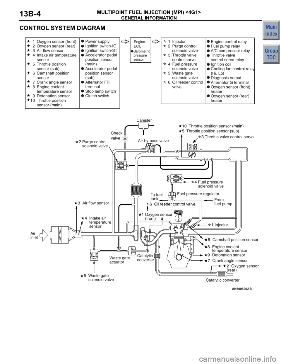
CONTROL SYSTEM DIAGRAM
AK600529AB
6 Oil feeder control valve
1 Oxygen sensor
(front)
8 Engine coolant
temperature sensor
3
Throttle valve control servo
10
Throttle position sensor (main)
5 Throttle position sensor (sub)
2 Purge control
solenoid valve
4 Fuel pressure
solenoid valve
7 Crank angle sensor
9
Detonation sensor
4
Intake air
temperature
sensor
3
Air flow sensor
Waste gate
actuator Canister
Check
valve Air by-pass valve
Fuel pressure regulatorFrom
fuel pump
To fuel
tank
Catalytic converter
Catalytic
converter
Air
inlet
Oxygen sensor (front)
Oxygen sensor (rear)
Air flow sensor
Intake air temperature
sensor
Throttle position
sensor
(sub)
Camshaft position
sensor
Crank angle sensor
Engine coolant
temperature sensor
Detonation sensor
Throttle position
sensor (main) Power supply
Ignition switch-IG
Ignition switch-ST
Accelerator pedal
position sensor
(main)
Accelerator pedal
position sensor
(sub)
Alternator FR
terminal
Stop lamp switch
Clutch switchEngine-
ECUEngine control relay
Fuel pump relay
A/C compressor relay
Throttle valve
control servo relay
Ignition coil
Cooling fan
control relay
(Hi, Lo)
Diagnosis output
Alternator G terminal
Oxygen sensor (front)
heater
Oxygen sensor (rear)
heater
Barometric
pressure
sensor
1 Injector
5 Waste gate
solenoid valve
2 Oxygen sensor
(rear)
6 Camshaft position sensor
1
2
3
4
5
6
7
8
9
10 Injector
Purge control
solenoid valve
Throttle valve
control servo
Fuel pressure
solenoid valve
Waste gate
solenoid valve
Oil feeder control
valve
1
2
3
4
5
6