belt MITSUBISHI COLT 2006 Service Repair Manual
[x] Cancel search | Manufacturer: MITSUBISHI, Model Year: 2006, Model line: COLT, Model: MITSUBISHI COLT 2006Pages: 364, PDF Size: 11.65 MB
Page 58 of 364
BASE ENGINE
ENGINE MECHANICAL <4A9>11A-10
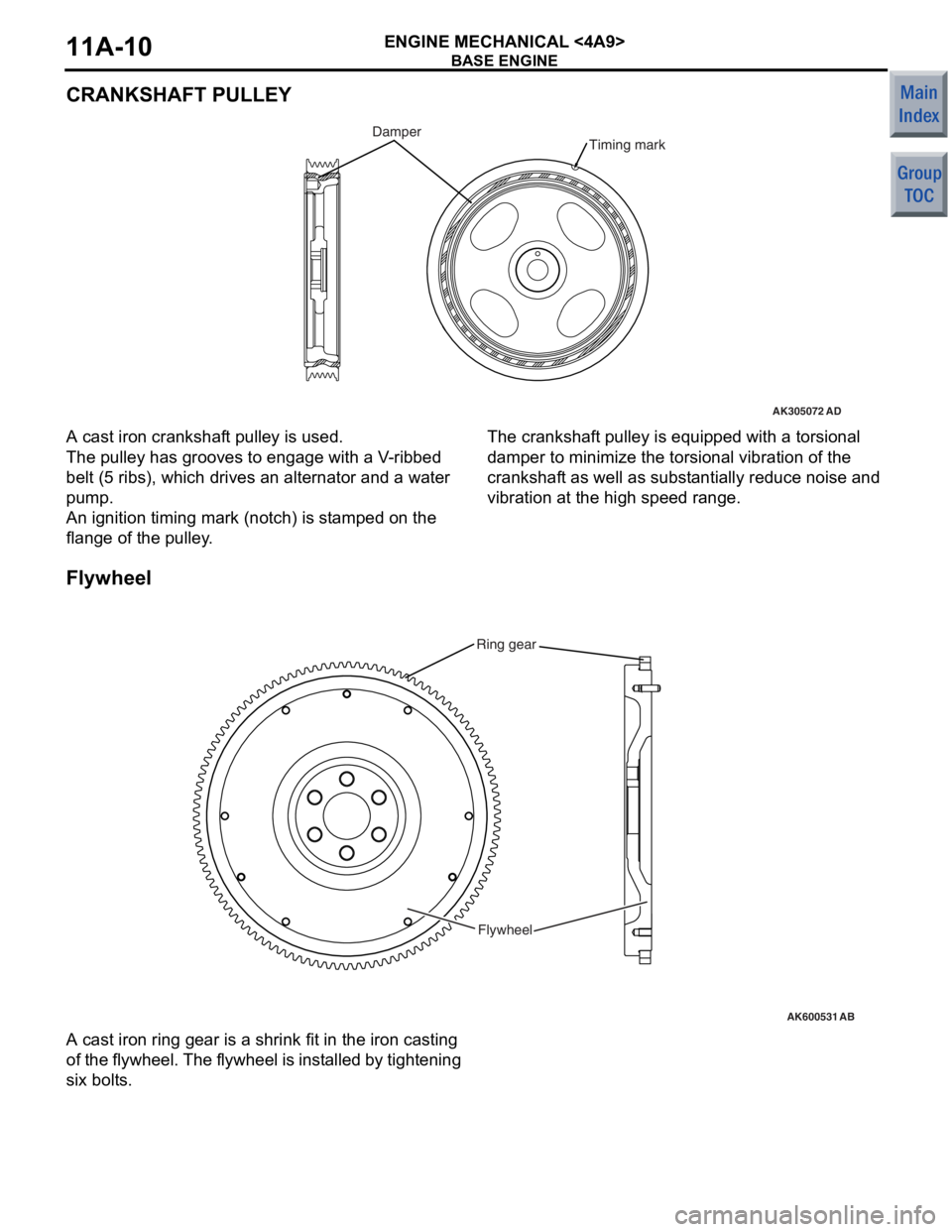
CRANKSHAFT PULLEY
AK305072AD
Timing markDamper
A cast iron cranksh af t pulley is used.
The pulley has grooves to eng age with a V -rib bed
belt (5
ribs), which drives an alternat or and a water
pump
.
An ignition timing mark (notch) is st amp ed on the
flang
e of the pulley .
The crankshaft pulley is equipped with a to rsio nal
damp
e r to minimize the torsional vibratio n of th e
cranksha
f t as well as sub s t antia lly redu ce no ise and
vib
r ation at the high spee d rang e.
Flyw he el
AK600531
Ring gear
Flywheel
AB
A cast iron ring g ear is a shrink fit in th e iron casting
of
t h e f l yw he el. T h e f l yw he el is in st a l le d by tigh t e n i n g
six bolt
s .
Page 74 of 364
BASE ENGINE
ENGINE MECHANICAL <4A9>11A-26
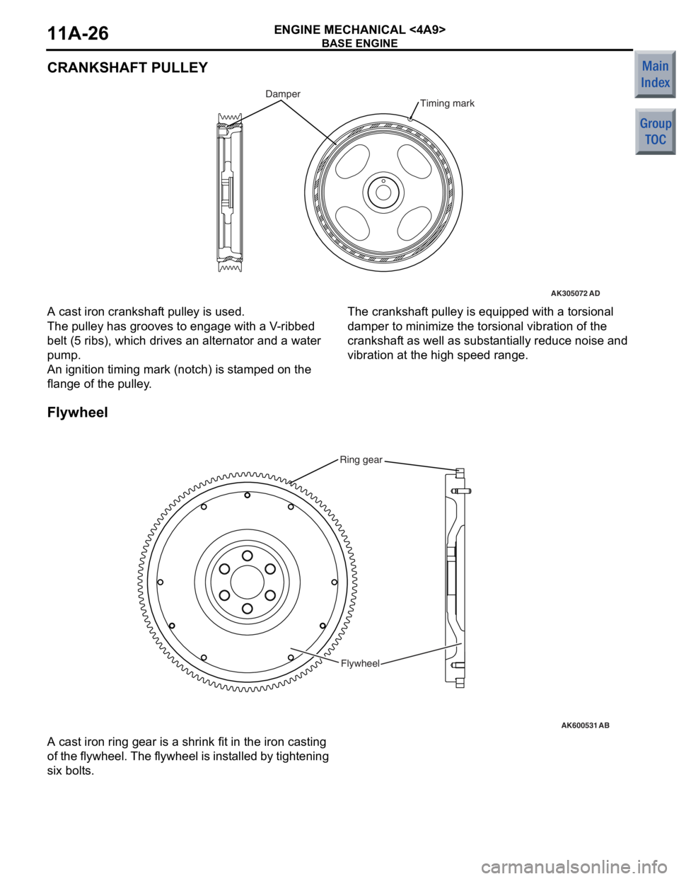
CRANKSHAFT PULLEY
AK305072AD
Timing markDamper
A cast iron cranksh af t pulley is used.
The pulley has grooves to eng age with a V -rib bed
belt (5
ribs), which drives an alternat or and a water
pump
.
An ignition timing mark (notch) is st amp ed on the
flang
e of the pulley .
The crankshaft pulley is equipped with a to rsio nal
damp
e r to minimize the torsional vibratio n of th e
cranksha
f t as well as sub s t antia lly redu ce no ise and
vib
r ation at the high spee d rang e.
Flyw he el
AK600531
Ring gear
Flywheel
AB
A cast iron ring g ear is a shrink fit in th e iron casting
of
t h e f l yw he el. T h e f l yw he el is in st a l le d by tigh t e n i n g
six bolt
s .
Page 181 of 364

COMBINATION METER
CHASSIS ELECTRICAL54A-10
COMBINATION METER
M2540005000894
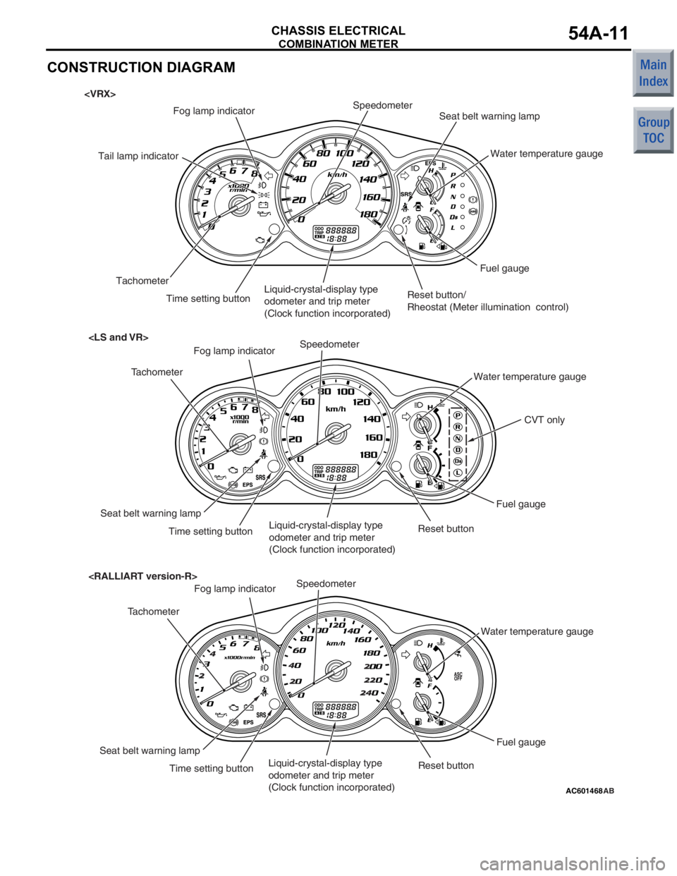
The combination meter features large, clearly visible
analogue indicators. The meter has the speedometer
in the middle, the coolant temperature gauge at
upper right, the fuel gauge at lower right, and the
tachometer at left so that drivers can easily distin
-
guish the information from the meters. The combina-
tion meter offers the following advantages.
•The combination meter is used for air conditioner
and meter drive control to integrate ECU.
•CAN communication is used for more reliable
transmission of all gauge data and indicator lamp
input signals, such as vehicle speed, engine
RPM, and coolant temperature. For further
details on CAN, refer to GROUP 54C, CAN
P.54C-2. The signals that the combination meter
uses are described in the CAN communications
input signals table
.
•Several diagnosis functions such as the diagno-
sis code memory and actuator tests are prepared
in order to improve serviceability.
•For a brighter display at night and for a longer
useful life, all indicator lamps, warning lamps, and
illumination bulbs use LEDs.
•The indicators for the speedometer, fuel gauge,
and other gauges are driven by a stepping motor.
For further details, consult the stepping motor
section
.
•The electronic speedometer operates by receiv-
ing vehicle speed signals sent by the
engine-ECU
via the CAN.
•A large and clear LCD type odo-tripmeter is pro-
vided. The odometer continuously displays val-
ues while the tripmeter adopts a twin-trip (trip A,
trip B) function which is switched by a reset but
-
ton. In addition, clock function is incorporated.
•A fog lamp indicator lamp is provided to let the
driver know that the fog lamp is on.
•A seat belt warning lamp is installed to encourage
the driver to fasten the seat belt.
•The high-contrast meter is adopted. When the
ignition is turned ON, such as the needles and
face display are illuminated with fade-in lighting
by the LED light source.
•To further accentuate the high-contrast lighting,
the light of the high-contrast meter fades in and
fades out when the light is turned on and off
respectively.
•With the auto illumination function incorporated in
the high-contrast meter, a two-stage switching of
daytime (non-dimming) and nighttime (dimming)
is achieved. Also, the brightness can be adjusted
using the illumination control knob.
•A tail lamp indicator lamp is installed which
informs the lighting status of the tail lamps to the
driver.
Page 182 of 364
COMBINATION METER
CHASSIS ELECTRICAL54A-11
CONSTRUCTION DIAGRAM
AC601468AB
Water temperature gauge
Seat belt warning lamp
SpeedometerFog lamp indicator
Fuel gauge
Time setting buttonLiquid-crystal-display type
odometer and trip meter
(Clock function incorporated)
Tachometer
Tachometer
Speedometer
Water temperature gauge
Fuel gauge
Liquid-crystal-display type
odometer and trip meter
(Clock function incorporated) Time setting button
Seat belt warning lampFog lamp indicator
Tail lamp indicator
Reset button/
Rheostat (Meter illumination control)
Reset button
CVT only
Water temperature gauge
Seat belt warning lamp
SpeedometerFog lamp indicator
Fuel gauge
Time setting buttonLiquid-crystal-display type
odometer and trip meter
(Clock function incorporated)
TachometerReset button
Page 192 of 364

TECHNICAL FEATURES
GENERAL00-7
FEATURES
Quality improvement
•Full interior trim
•Two-tone interior
•Cloth covered part door trim
Usability improvement
•Movable ashtray
•Front RECARO seat (Option)
•Cup holder of right/left separation type (for front
seats)
•Convenience hook (passenger’s side)
•Wide variety of seat arrangement
•Reclining adjustment, slide adjustment
•Luggage hook
•High-contrast meter
•Combination meter of 240km/h scale
Convenient boxes
•Centre panel box
•Glove box
•Seatback pocket
•Bottle holder (front door trim)
•Door pocket (front door trim)
Safety improvement
•ELR three-point seat belt (front)
•Front seat belt with force limiter mechanism
•ELR three-point seat belt/child seat fastening
mechanism (ALR) switching seat belt (rear)
•Floor carpet with heel stopper structure
•Instrument panel and trims which adopt
fire-retarding materials
Consideration for the optimum driving position
•Seat height adjustment (driver’s seat)
•Head restraint with height adjustment (front, rear)
•One-touch adjustable seat belt anchor (front seat
belt)
Measures for resource recycling
Aggressively use PP materials that are easy to recy-
cle and easy to stamp material symbols on the plas-
tic (resin) parts.
Page 196 of 364

TECHNICAL FEATURES
GENERAL00-11
CVT
The F1C1A transmission is adopted for the CVT.
This transmission is basically the same as conven
-
tional transmission.
The ATF warmer (ATF cooler) is adopted.
SPECIFICATIONS
ItemSpecification
Transmission modelF1C1A
Engine model4A91
Torque converterTy p e3-element, 1-stage, 2-phase type
Lock-upProvided
Stall torque ratio2.0
Transmission typeForward automatic continuously variable (steel belt type),
1st in reverse
Gear ratioForward2.319 − 0.445
Reverse2.588
ClutchA pair of multi-plate system
BrakeA pair of multi-plate system
Manual control systemP-R-N-D-Ds-L (smart shift)
FunctionVariable speed controlYe s
Line pressure controlYe s
Direct engagement controlYe s
N-D/N-R controlYe s
Shift pattern controlYe s
Self-diagnosisYe s
FailsafeYe s
Oil pumpTy p eExternal gear pump
ConfigurationBuilt-in (chain drive)
Control methodElectronic control (INVECS-III)
Page 210 of 364
TECHNICAL FEATURES
GENERAL00-25
SUPPLEMENTAL RESTRAINT SYSTEM
(SRS*)
NOTE: *SRS: Supplemental Restraint System
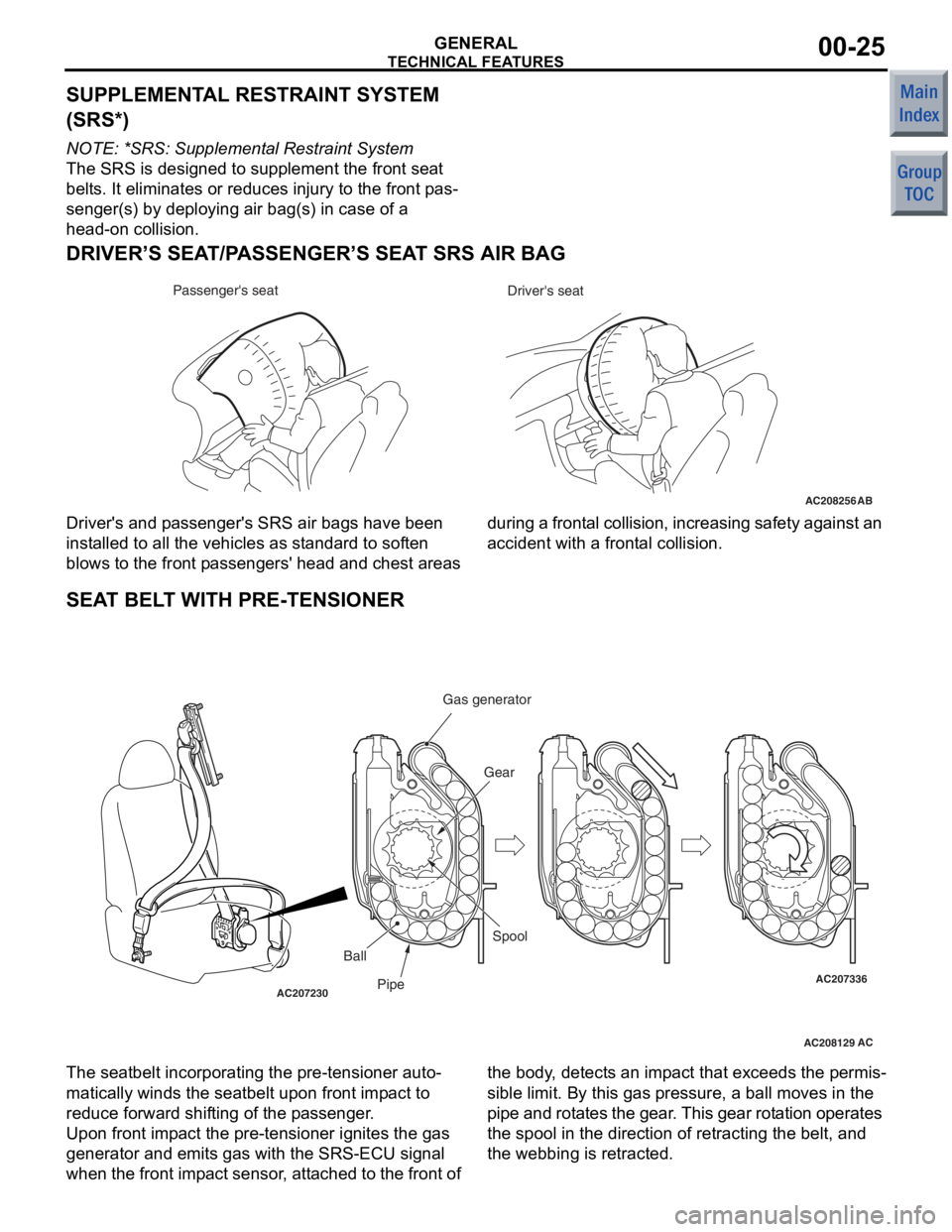
The SRS is designed to supplement the front seat
belts. It eliminates or reduces injury to the front pas
-
senger(s) by deploying air bag(s) in case of a
head-on collision.
DRIVER’S SEAT/PASSENGER’S SEAT SRS AIR BAG
AC208256AB
Driver's seat
Passenger's seat
Driver's and
pa sse nger's SRS a ir bag s have be en
inst alled to all the vehicle s as st andard to sof ten
blows to the front pa sseng ers' head and che st areas d
uring a fro nta l coll ision , i n cre asin g sa fety a gainst an
acciden t with a frontal collision.
SEAT BEL T WITH PRE-TENSIONER
AC208129
AC207230AC207336
ACPipe Gear
Ball Spool
Gas generator
The seatbelt incorpo
rating the pre -tensioner auto-
matically winds the seatbelt upo n front impact to
reduce forward shif ting of the passenge r.
Upo n front impact the pre-ten sion er ig nites the g as
generat or and emits gas with the SRS-ECU signal
whe n t he front imp act sen sor , att ached to the front of the bo
dy, det ects a n imp act t hat excee ds t he pe rmis
-
sible limit. By th is gas p ressure, a ball moves in th e
p ipe and rot ates the ge ar. This gear rotation operate s
the spool in the direction of ret racting the belt, and
the webbing is retr acted.
Page 211 of 364
TECHNICAL FEATURES
GENERAL00-26
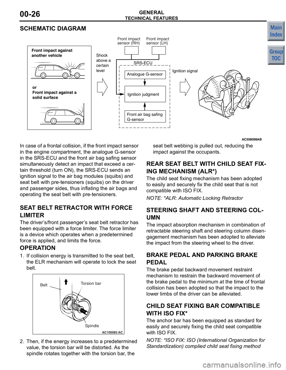
SCHEMATIC DIAGRAM
AC508098
Front impact against
another vehicleor
Front impact against a
solid surface Analogue G-sensor
Ignition judgment
Shock
above a
certain
level
Ignition signal
SRS-ECU
Front air bag safing
G-sensor
Front impact
sensor (RH)
Front impact
sensor (LH)
AB
In case of a
frontal collision, if the front imp act sensor
in the engine comp artment, the analogue G-sensor
in the SRS-ECU and t he front air bag safing sensor
simult aneously de tect an imp act th at excee d a cer
-
ta in threshold (turn ON), the SRS-ECU sen ds an
ignition signal to the air bag modules (squ ibs) and
seat belt with pre-te nsioners (squibs) on the driver
and p asseng er sides, thus inflating the air bag s and
operating the seat belt with pre -tensioner s.
SEAT BEL T RETRACT OR WITH FORCE
LIMITE R
The driver ’s /front p asseng er’s seat belt retractor has
been e quipped with a force limit er. The force limiter
is a device which operat es when a predetermined
force is applied, an d limits the for ce.
OPERA TION
1. If collision energy is transmit ted to the seat belt,
th e ELR mechanism will oper ate to lock the seat
be lt.
AC100083
Torsion bar
Spindle
Belt
AC
2.
Then, if the en ergy increase s to a prede termined
value , the to rsion bar will b e distorted . As th e
spind le rot ate s tog ether with the t orsion bar , the seat b
elt webb ing is p ulle d out, reducing th e
imp act against t he occupants.
REAR SEA T BELT WITH CHILD SEA T FIX-
ING MECHANISM (ALR*)
The child seat fixing mechanism h as b een ad opted
to easily and securely fix the child seat that is not
comp atible with ISO FIX.
NO TE: *ALR: Automatic Lockin g Retractor
STEERING SHAFT AND STEERING COL-
UMN
The impact ab sorption mech anism in combin ation of
retract able steerin g shaft and steering co lumn disen
-
gagement mecha nism has been ad opted t o alle viate
the imp act from th e steering wheel to the d rive r.
BRAKE PEDAL AND PA RKING BRAKE
PEDAL
The bra ke pe dal b ackward mo vement restraint
mechanism to restrain the backward movement of
the brake p edal to the minimum at the time o f f ront al
collision h as b een ad opted so that the impact to th e
lower limb s of the driver can be alleviated.
CHILD SEAT FIXING BAR COMP ATIBLE
WITH ISO FIX*
The an chor bar has been equipped a s st andard fo r
easily and secu rely fixing the child seat comp atible
with ISO FIX.
NO TE: *ISO F IX: ISO (In ternational Orga nization for
S tand ardizatio n) complied child se at fixing method
Page 212 of 364
TECHNICAL FEATURES
GENERAL00-27
POWER WINDOW WITH SAFETY MECHA-
NISM
The power window with safety mechanism has been
adopted to automatically roll down and stop the door
window glass as soon as the occurrence of jamming
is detected at the time of rolling up the door window
glass.
SUNROOF WITH SA FETY MECHANISM
The sunroof with safe ty mechanism has been
adopted so that the roof lid glass can move in the
reverse direction and stop when application of exter
-
nal force hinders the movement during the sliding to
close or tilt down operation.
TRIMS AND HEADLINING
The head impact absorption structure has been
adopted for the pillar trim, quarter trim, and headlin
-
ing so that impact towards the head of a passenger
can be reduced.
OTHER SAFETY FEATURES
•3-point ELR seat belts
•Child-protection rear door locks
•Front fog lamps
EQUIPMENTSM2000026000221
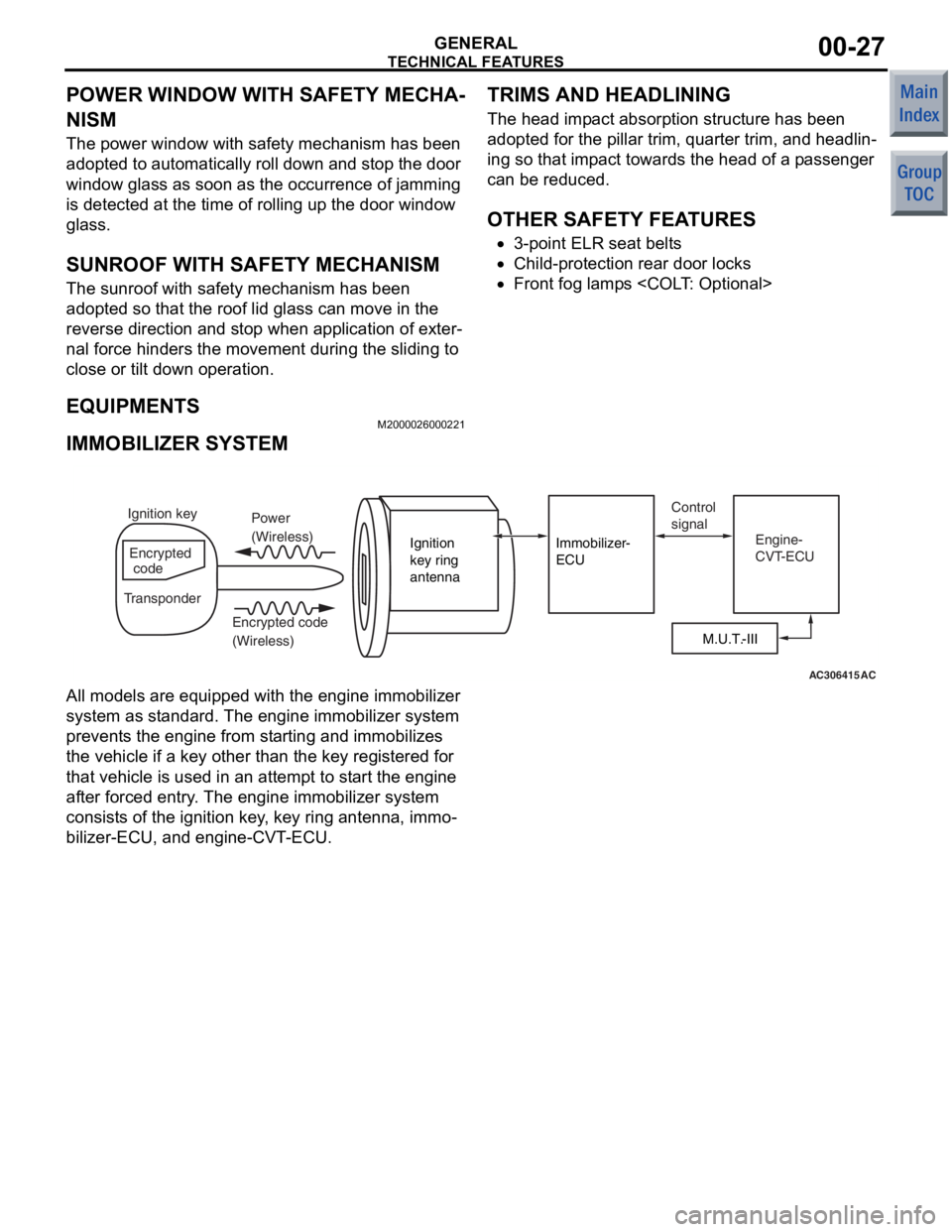
IMMOBILIZER SYSTEM
AC306415AC
M.U.T.-III
Ignition
key ring
antenna
Immobilizer-
ECU
Ignition key
Encrypted
code
Transponder Power
(Wireless)
Encrypted code
(Wireless) Control
signal
Engine-
CVT-ECU
All models are equipped with the e ngine immobilizer
system as st andard. The en gine immobilizer syst em
preve nts the engin e from starting and immobilizes
the vehicle if a key o ther tha n the key registered for
that vehicle is used in an attempt to start the e ngine
af te r forced entry . The en gine immobilizer syst em
consist s of the ignition key, key ring antenna, immo
-
bilizer-ECU, and engine-CVT-ECU.
Page 214 of 364

TECHNICAL FEATURES
GENERAL00-29
IMPROVED SERVICEABILITY
•Employment of an automatic hydraulic timing belt
tensioner offers timing belt reliability, reduced
operating noise, and better serviceability. <4G1>
•Wiring harness section of the crank angle sensor
has been moulded integrally with the timing belt
cover, improving serviceability and reliability.
<4G1>
•Due to the adoption of the timing chain and the
timing chain tensioner, maintenance-free and reli
-
ability have been improved. <4A9>
•Since adoption of unvolatile memory (EEPROM*)
helps the learned value not to be initialised when
the battery terminal or connector of the control
unit is disconnected, maintainability can be
improved.
NOTE: *EEPROM: Electrical Erasable Programma-
ble ROM (information to be memorised can be
electronically written into and erased from ROM)
•Since the adoption of electric power steering
makes hydraulic pipes and oil pumps unneces
-
sary, maintainability can be improved.
•Employment of operative A/C piping layout and
refrigerant leak detection system enhances serv
-
iceability.