belt MITSUBISHI COLT 2006 Service Owner's Manual
[x] Cancel search | Manufacturer: MITSUBISHI, Model Year: 2006, Model line: COLT, Model: MITSUBISHI COLT 2006Pages: 364, PDF Size: 11.65 MB
Page 297 of 364

GENERAL INFORMATION
SUPPLEMENTAL RESTRAINT SYSTEM (SRS)52B-5
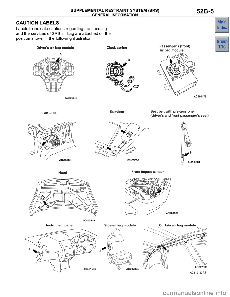
CAUTION LABELS
Labels to indicate cautions regarding the handling
and the services of SRS air bag are attached on the
position shown in the following illustration.
AC510120
AC206616
AC206284
AC206096AC206281
AC206097
AC400175
AC401506AC207325AC207330
AC402445
AB
A Clock spring
B
Driver's air bag module
Passenger's (front)
air bag module
SRS-ECUSunvisor
F
Seat belt with pre-tensioner
(driver's and front passenger's seat)
Hood
G Front impact sensor
IJK
Curtain air bag module
Side-airbag module
Instrument panel C
D EE
H
Page 298 of 364

GENERAL INFORMATION
SUPPLEMENTAL RESTRAINT SYSTEM (SRS)52B-6
Label contents
ADANGER FLAMMABLE MATERIAL
TO PREVENT PERSONAL INJURY. DO NOT DISMANTLE, INCINERATE, OR BRING
INTO CONTACT WITH ELECTRICITY. STORE BELOW 200
°F (93°C). READ SERVICE
MANUAL FOR DETAIL.
BCAUTION: SRS CLOCK SPRING
THIS IS NOT A REPAIRABLE PART. IF DEFECTIVE, REPLACE ENTIRE UNIT
ACCORDING TO THE SERVICE MANUAL INSTRUCTIONS. TO RE-CENTRE: ROTATE
CLOCKWISE UNTIL TIGHT. THEN ROTATE IN OPPOSITE DIRECTION ROUGHLY 3
3/4 TURNS AND ALIGN ARROWS >><<.
CDANGER FLAMMABLE MATERIAL
TO PREVENT PERSONAL INJURY. DO NOT DISMANTLE, INCINERATE, OR BRING
INTO CONTACT WITH ELECTRICITY. STORE BELOW 200
°F (93°C). READ SERVICE
MANUAL FOR DETAIL.
DCAUTION:
DO NOT DISASSEMBLE OR DROP. IF DEFECT REFER TO SERVICE MANUAL.
E
WARNING
•DEATH OR SERIOUS INJURY can occur.
•ALWAYS use SEAT BELT and CHILD SEAT.
•DO NOT sit or lean unnecessarily close to the air bag.
•DO NOT place or install any objects over the air bag or between the air bag and
yourself.
WARNING
•DEATH OR SERIOUS INJURY can occur
•DO NOT place rear-facing child seat on this seat with airbag.
FDANGER: SEAT BELT PRETENSIONER
DO NOT DISASSEMBLE OR IMPACT
REFER TO SERVICE MANUAL FOR INSTRUCTIONS, HANDLING, STORAGE AND
DISPOSAL PROCEDURES.
GWARNING
THIS VEHICLE HAS AN AIR BAG SYSTEM. REFER TO SERVICE MANUAL BEFORE
SERVICING OR DISASSEMBLING UNDERHOOD COMPONENTS. READ THE "SRS"
SECTION OF MANUAL FOR IMPORTANT INSTRUCTIONS. IMPROPER SERVICE
PROCEDURES CAN RESULT IN THE AIR BAG FIRING OR BECOMING
INOPERATIVE, POSSIBLY LEADING TO INJURY.
HCAUTION:
DO NOT DISASSEMBLE OR DROP.
Page 300 of 364

SYSTEM OPERATION
SUPPLEMENTAL RESTRAINT SYSTEM (SRS)52B-8
SYSTEM OPERATION
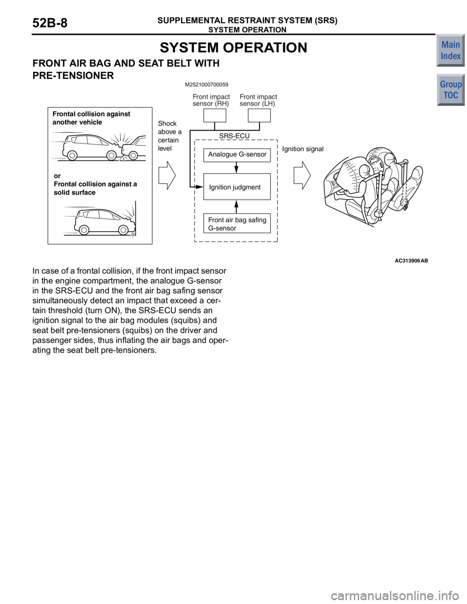
FRONT AIR BAG AND SEAT BELT WITH
PRE-TENSIONER
M2521000700059
AC313906
Frontal collision against
another vehicleor
Frontal collision against a
solid surface Analogue G-sensor
Ignition judgment
Shock
above a
certain
level
Ignition signal
SRS-ECU
Front air bag safing
G-sensor
Front impact
sensor (RH)
Front impact
sensor (LH)
AB
In case of a
front a l collision, if the front imp a ct sensor
in the
engine comp artment, th e ana logue G-sensor
in the
SRS-ECU and t he fron t air b ag sa fing sensor
simult
ane ously de tect an imp a ct th at excee d a cer
-
ta in threshold (turn ON), the SRS-ECU sen d s an
ignition
sign al to the air bag modu les (squ ibs) and
seat
belt p r e-tension e rs (squib s ) on the driver and
p
a sse nger sid e s, thus inflating the air bags an d op er
-
ating the seat be lt pre - tensioners.
Page 305 of 364

SYSTEM CONSTRUCTION
SUPPLEMENTAL RESTRAINT SYSTEM (SRS)52B-13
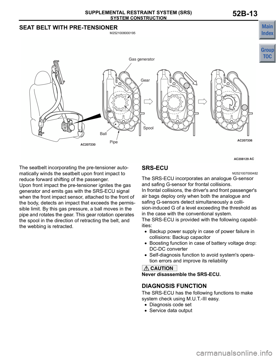
SEAT BELT WITH PRE-TENSIONER
M2521008000195
AC208129
AC207230AC207336ACPipe Gear
Ball Spool
Gas generator
The seatbelt incorpo
r ating the pre - tensioner auto-
matically winds the seatbelt upo n front imp a ct to
reduce forward shif
ting of th e p a ssenge r .
Upon front imp a ct the pre-ten s ion e r ig nites the g a s
generat
or and emit s gas with the SRS-ECU signal
whe
n t he front imp a ct sen s or , att a ched to the front of
the bo
dy , dete c t s a n imp a ct t hat excee d s t he per mis
-
sible limit. By this g a s p r essure, a ball moves in the
p
i p e and rot a tes the g ear . This gear rot a tion operat es
the spool
in the directio n of ret r acting the belt, and
the webbing is retra
c ted .
SRS-ECU
M25210070 0048 2
The SRS-ECU incorp orates an an alog ue G-sensor
and safing
G-sensor for fro n t a l collisions.
In frontal collision s , the dr iver's an d front p a ssenge r's
air ba
gs d eploy only when both t he ana logue and
safing G-sensors detect
simult a neously a co lli
-
sion -indu ced G of a le vel exceed ing the thresh old as
in the
case with the conve n tion al system.
The SRS-ECU is prov ide d with t he followin g cap a b i l-
ities:
•Backup p o wer su pply in case of po we r failure in
c
o lli si ons: Ba cku p ca p a cito r
•Boosting function in ca se of battery volt a ge drop :
DC-DC converter
•Self-diag nosis fu nction to a v oid syste m 's opera-
tion errors and imp r ove it s reliabilit y
CAUTION
Never disassemble the SRS-ECU.
DIAGNOSIS FUNCTION
The SRS-ECU has the following functions to make
system check using M.U.T.-III easy.
•Diagnosis code set
•Service data output
Page 307 of 364

SYSTEM CONSTRUCTION
SUPPLEMENTAL RESTRAINT SYSTEM (SRS)52B-15
32SRS-ECU capacitor circuit voltage too low
34*2SRS-ECU connector lock out of order
35Ignition of the air bag completed
39Simultaneous deployed
41*2Power supply voltage (IG1 (A) voltage) drops abnormally.
42*2Power supply voltage (IG1 (B) voltage) drops abnormally.
43*2SRS warning lamp circuit open-circuited
44*2SRS warning lamp circuit malfunction
45SRS-ECU non-volatile memory (EEPROM) and A/D converter system
51Driver's air bag squib activating circuit short-circuited
52Driver's air bag squib activating circuit open-circuited
54Passenger's (front) air bag squib activating circuit short-circuited
55Passenger's (front) air bag squib activating circuit open-circuited
56Driver’s seat belt pre-tensioner (squib ignition drive circuit) system detected short
57Driver’s seat belt pre-tensioner (squib ignition drive circuit) system detected open
58Passenger’s seat belt pre-tensioner (squib ignition drive circuit) system detected short
59Passenger’s seat belt pre-tensioner (squib ignition drive circuit) system detected open
61Driver's air bag squib drive circuit (power supply side) short-circuited
62Driver's air bag squib drive circuit (earth side) short-circuited
64Passenger's (front) air bag squib drive circuit (power supply side) short-circuited
65Passenger's (front) air bag squib drive circuit (earth side) short-circuited
66Driver's pre-tensioner squib (power supply side) short-circuited
67Driver's pre-tensioner squib (earth side) short-circuited
68Passenger's (front) pre-tensioner squib drive circuit (power supply side) short-circuited
69Passenger's (front) pre-tensioner squib drive circuit (earth side) short-circuited
71*3Side-airbag squib (RH) short-circuited
72*3Side-airbag squib (RH) open-circuited
73Side-airbag squib (RH) drive circuit shorted
74Side-airbag squib (RH) drive circuit open
75Side-airbag squib (RH) drive circuit (power supply side) shorted
76Side-airbag squib (RH) drive circuit (earth side) shorted
79Side impact sensor (LH) communication error
81*3Side-airbag squib (LH) shot-circuited
82*3Side-airbag squib (LH) open-circuited
83Side-airbag squib (LH) drive circuit shorted
84Side-airbag squib (LH) drive circuit open
85Side-airbag squib (LH) drive circuit (power supply side) shorted
86Side-airbag squib (LH) drive circuit (earth side) shorted
89Side impact sensor (RH) communication error
CODE NO. MAJOR CONTENTS OF DIAGNOSTICS
Page 309 of 364

SYSTEM CONSTRUCTION
SUPPLEMENTAL RESTRAINT SYSTEM (SRS)52B-17
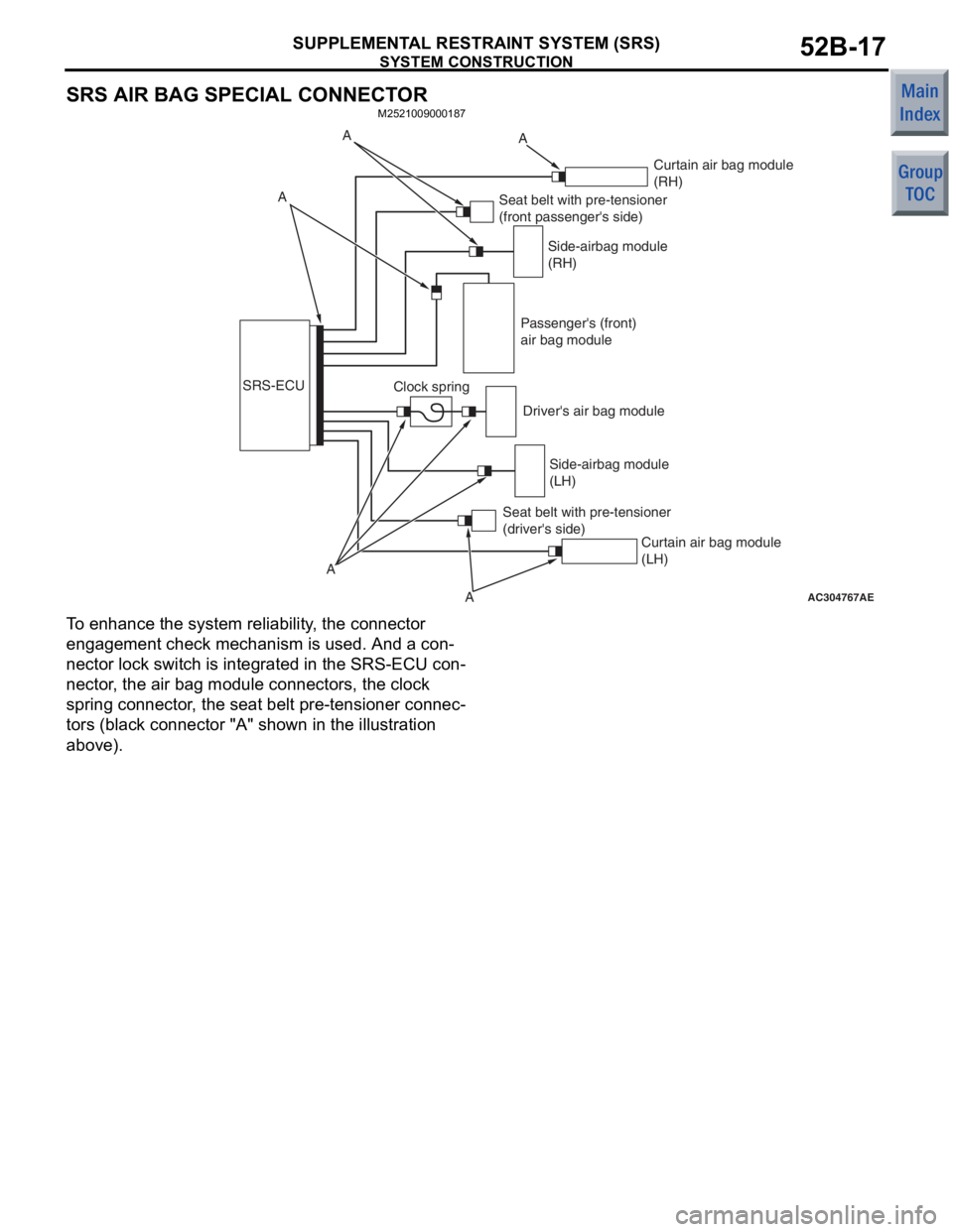
SRS AIR BAG SPECIAL CONNECTOR
M2521009000187
AC304767
SRS-ECUA
A
AAE
Clock spring Side-airbag module
(RH)
Seat belt with pre-tensioner
(front passenger's side)
Side-airbag module
(LH)
Seat belt with pre-tensioner
(driver's side) Passenger's (front)
air bag module
Driver's air bag module Curtain air bag module
(RH)
Curtain air bag module
(LH)
AA
T o en hance the system reliability , th e con nect o r
engage
ment che ck mechanism is u s ed. An d a con
-
nector lock switch is integ r ated in the SRS-ECU con-
nector , the a i r ba g mod u le conne ctors, the clo ck
spring co
nnector , the sea t belt pre-ten s io ner connec
-
tors (black connector "A" shown in the illustration
above).
Page 350 of 364

CVT
CONTINUOUSLY VARIABLE TRANSMISSION (CVT)23-2
CVT
GENERAL INFORMATIONM2231000100165
The F1C1A transmission is adopted for the CVT.
This transmission is basically the same as conven
-
tional transmission.
The ATF warmer (ATF cooler) is adopted.
SPECIFICATIONS
ItemSpecification
Transmission modelF1C1A
Engine model4A91
Torque converterTy p e3-element, 1-stage, 2-phase type
Lock-upProvided
Stall torque ratio2.0
Transmission typeForward automatic continuously variable (steel belt type),
1st in reverse
Gear ratioForward2.319 − 0.445
Reverse2.588
ClutchA pair of multi-plate system
BrakeA pair of multi-plate system
Manual control systemP-R-N-D-Ds-L (smart shift)
FunctionVariable speed controlYe s
Line pressure controlYe s
Direct engagement controlYe s
N-D/N-R controlYe s
Shift pattern controlYe s
Self-diagnosisYe s
FailsafeYe s
Oil pumpTy p eExternal gear pump
ConfigurationBuilt-in (chain drive)
Control methodElectronic control (INVECS-III)
Transmission oilSpecified lubricantsDIA QUEEN ATF SP III
Quantity L8.1
Page 352 of 364

CVT
CONTINUOUSLY VARIABLE TRANSMISSION (CVT)23-4
DIAGNOSIS CLASSIFICATION TABLE
M2231015000056
ItemDiagnosisData listActuator
test
Code No.Trouble symptomsItem No.Display
Crank angle sensor−−01r/min−
CVT fluid temperature sensor15Open circuit08°C−
16Short circuit
Line pressure sensor18Open circuit09MPa−
19Short circuit
Turbine speed sensor22Open circuit02r/min−
Primary speed sensor23Open circuit03r/min−
26System failure
Secondary speed sensor24Open circuit04r/min−
25System failure
Accelerator pedal position sensor (APS)−−06mV−
Primary pressure sensor27Open circuit11MPa−
28Short circuit
Gear ratio−−12Displays the
gear ratio.−
Line pressure control solenoid valve31Open circuit/short
circuit 16%01
Shift control solenoid valve32Open circuit15%02
36Short circuit
Damper clutch control solenoid valve33Open circuit14%03
37Short circuit
Clutch pressure control solenoid valve34Open circuit17%04
38Short circuit
Shift system42System failure−−−
Damper clutch system44System failure10r/min−
45
Clutch system46System failure−−−
48
Inhibitor switch51Open circuit26P/R/N/D/Ds/L−
52Short circuit
Stop lamp switch53Open circuit33ON/OFF−
54Short circuit
Battery voltage−−24V−
CVT control relay56Open circuit25V11
Steel belt system59System failure−−−
Line pressure system57System failure−−−
71
72