disc MITSUBISHI COLT 2006 Service Repair Manual
[x] Cancel search | Manufacturer: MITSUBISHI, Model Year: 2006, Model line: COLT, Model: MITSUBISHI COLT 2006Pages: 364, PDF Size: 11.65 MB
Page 6 of 364
CONSTRUCTION DESCRIPTION
ANTI-SKID BRAKE SYSTEM (ABS)35B-6
CONSTRUCTION DESCRIPTION
SENSORSM2351001000427
WHEEL SPEED SENSORS AND MAG-
NETIC ENCODER FOR WHEEL SPEED
DETECTION
AC601358
Rear wheel speed sensor
Front wheel speed sensor
Front Rear
Encoder for wheel
speed detection Encoder for wheel
speed detectionRear wheel speed sensor
Encoder for wheel
speed detection
AB
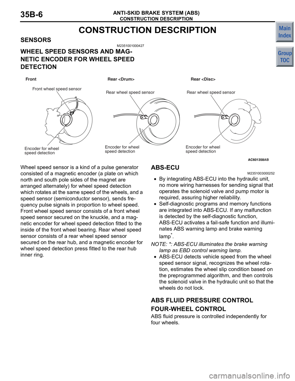
Wheel spee d se nsor is a kin d of a pulse gen erator
consisted of
a mag netic encoder (a pla t e on which
north an
d so uth po le sides of th e mag net are
arrange
d alte rnately) for wh eel speed detection
which rot
a tes at the same speed of the wheels, and a
spee
d sen s or (semicon duct o r se nsor), send s fre
-
quency pulse sig nals in proportion to wh eel spee d.
Front wheel sp eed sensor co nsist s of a front whe e l
spee
d sen s or secu red on the knuckle, and a mag
-
netic encoder for wheel spee d dete c tio n fitt ed to th e
inside o
f the fro n t wheel bearing. Rear wh eel speed
sensor consist
s o f a rear wh eel speed sensor
secured on
the re ar hub, and a magn etic encoder fo r
whe
e l speed detection press fit t ed to the rear hub
inner ring.
ABS-ECU
M23510030 0025 2
•By integrating ABS-ECU into the hydraulic unit ,
no
more wiring h a rnesses for sending signal that
ope
rates the solen o id valve an d pump mo tor is
requ
ired, assuring high er reliability .
•Self-diag nostic p r ograms an d memory functions
are
integrated into ABS-ECU. If any malfunction
is dete
c ted by th e se lf-diagnostic function,
ABS-ECU activates
a fail-s afe function and illumi
-
nates ABS warning lamp and brake warning
la
mp
*.
NO TE: *: ABS-E CU illuminates the brake warning
l
a
m
p as EBD c o nt ro l wa rn in g la m p .
•ABS-ECU detects vehicle speed from the wheel
speed sensor signal, reco
gnizes the whee l rot a
-
tion, estimates the wheel slip condition based on
the
preprog rammed algorithm, a nd the n co ntrols
th
e soleno id valve in the hydr aulic u n it so th at the
wheels d
o not lock.
ABS FLUID PRESSURE CONTROL
FOUR-WHEEL CONTROL
ABS fluid pressure is controlled indep enden tly for
four whee
ls.
Page 10 of 364

CONSTRUCTION DESCRIPTION
ANTI-SKID BRAKE SYSTEM (ABS)35B-10
NOTE: .
•*: If any trouble occurs in CAN communication,
the brake warning lamp and ABS warning lamp
on the combination meter turns ON.
•Prohibit: Any controls are not performed until the
ignition switch is turned OFF.
•System shut-down: Control will be disabled until
valve power supply is turned off, and then ignition
switch is turned to the OFF position.
•Wait: ABS control is restarted when the normal
condition is resumed even though the ignition
switch is not turned OFF.
DIAGNOSTIC FUNCTION
ABS-ECU has the following functions for easier sys-
tem checks. The following items can be diagnosed
using the M.U.T.-III (ABS warning lamp illuminates
and ABS control is prohibited while the ABS-ECU
communicates with the M.U.T.-III).
•Diagnosis code set
•Service data output
•Actuator test
DIAGNOSIS CODE SET
There are 28 diagnostic items. Since all the diagnos-
tic results are recorded in volatile memory (EEP-
ROM*), they are stored in the memory even though
the battery terminals are disconnected.
NOTE: .
•*EEPROM (Electrical Erasable &;Programmable
ROM): Special type of memory that can be pro
-
grammed or erased electrically
•For each diagnostic item, refer to Fail-safe Func-
tion.
C1607Trouble in
ABS-ECUSystem
shut-downSystem
shut-downOutput
permitted
(Output may
be
impossible).ONON
Trouble in
ABS-ECU (CAN
Initialisation
malfunction)EnabledEnabledOutput
impossibleON *ON *
C1860High voltage at
ABS-ECU power
supplyWaitWaitOutput
permittedONON
C1861Low voltage at
ABS-ECU power
supplyWaitWaitOutput
permittedONON
U1073Trouble in CAN bus
systemEnabledEnabledOutput
impossibleON *ON *
Diagnosis
code No.Item Action during fail-safe operation
ABS control EBD control CAN output Brake
warning
lampABS
warning
lamp
Page 27 of 364

GENERAL INFORMATION
HEATER, AIR CONDITIONER AND VENTILATION55-3
SPECIFICATION
ItemSpecification
Heater unit typeTwo-layer full blow air mix method
Heater control typeDial type
A/C switch typePush button type
Compressor typeMSC60CA
RefrigerantTy p eHFC134a
Charge quantity g550 ± 20
PART MANUFACTURER
ItemManufacturer
A/C controller amplifierMitsubishi Heavy Industries Ltd.
Liquid pipe A
Liquid pipe B
Discharge flexible hose
Suction flexible hose
Compressor
Heater control panelAnsei Co., Ltd.
Heater unitDenso Corporation
Air intake box
CondenserZexel Valeo Climate Control
Corporation
Page 28 of 364
GENERAL INFORMATION
HEATER, AIR CONDITIONER AND VENTILATION55-4
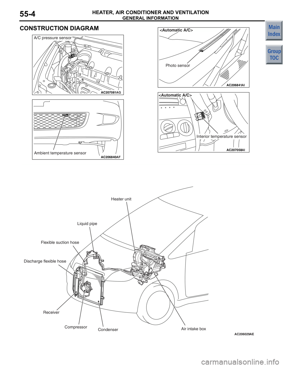
CONSTRUCTION DIAGRAM
AC207081AG
A/C pressure sensor
AC206840Ambient temperature sensorAF
AC206841
AI
Photo sensor
AC207058
Interior temperature sensor
AI
AC206029AE
Heater unit
Liquid pipe
Flexible suction hose
Discharge flexible hose
Receiver Compressor Condenser Air intake box
Page 171 of 364
GENERAL INFORMATION
CLUTCH21-2
GENERAL INFORMATION
M2210000100375
Due to the addition of vehicles with M/T, the dry sin-
gle plate diaphragm spring type is adopted to the
clutch and the hydraulic type is used for control sys
-
tem.
SPECIFICATIONS
ItemSpecification
Transmission modelF5MGAF5MGB
Clutch disc typeDry single plate type
Clutch disc facing diameter OD x ID mm200 × 140216 × 144
Clutch cover typeDiaphragm spring type
Clutch cover setting load N3,600 − 4,1005,400 − 6,000
Control systemHydraulic type
Clutch fluidMitsubishi genuine diamond queen brake fluid super 4
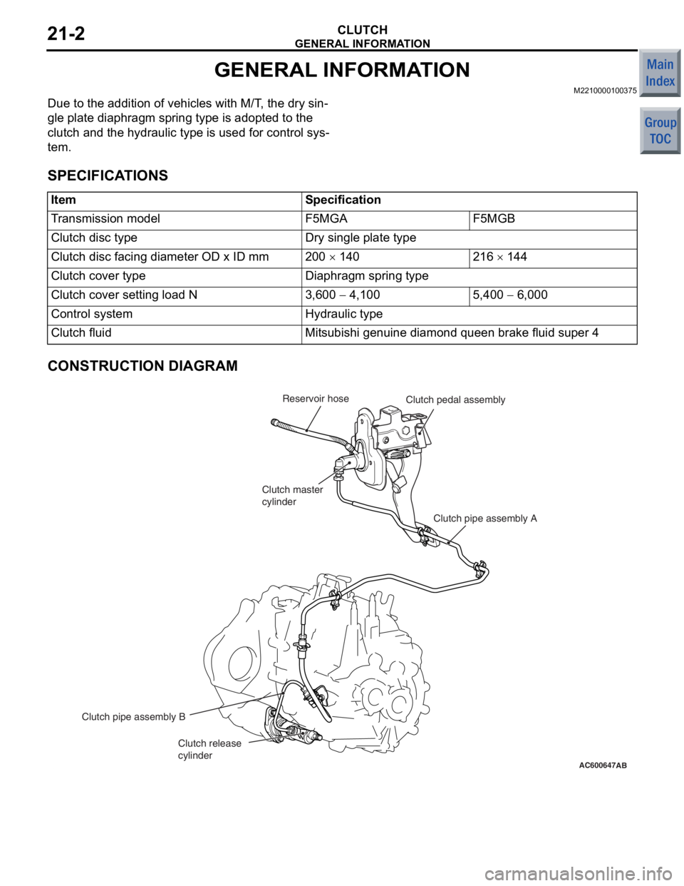
CONSTRUCTION DIAGRAM
AC600647
Clutch pipe assembly A
Clutch pipe assembly B
AB
Reservoir hose Clutch pedal assembly
Clutch release
cylinder Clutch master
cylinder
Page 200 of 364
TECHNICAL FEATURES
GENERAL00-15
BRAKE
M2000024000270
SERVICE BRAKE
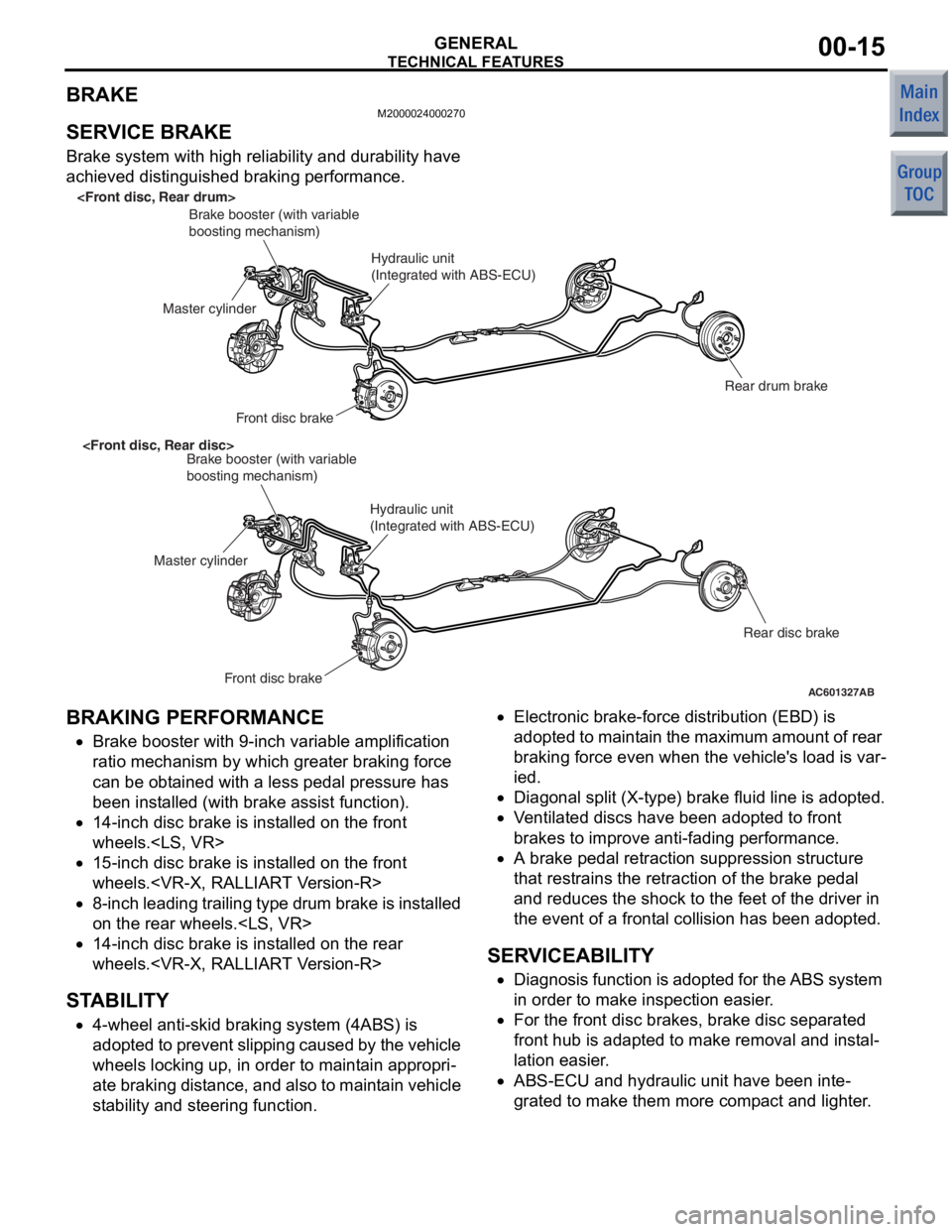
Brake system with high reliability and durability have
achieved distinguished braking performance.
AC601327AB
Brake booster (with variable
boosting mechanism)
Master cylinder Front disc brake
Hydraulic unit
(Integrated with ABS-ECU)
Rear drum brake
Brake booster (with variable
boosting mechanism)
Master cylinder
Front disc brake
Hydraulic unit
(Integrated with ABS-ECU) Rear disc brake
BRAKING PERFORMANCE
•Brake booster with 9-inch variab le amplificatio n
ratio me chanism by which greate r braking f orce
ca n be o bta ined with a less ped al pressure has
bee n inst alled (with b rake assist function).
•14-inch disc bra ke is inst alled on the front
wheels.
•15-inch disc bra ke is inst alled on the front
wheels.
•8-inch leading trailing type drum brake is installed
on the rear wheels.
•14-inch disc bra ke is inst alled on the rear
wheels.
ST ABILITY
•4-wheel anti-skid brak ing system (4ABS) is
ado pted to pre vent slippin g cause d by the vehicle
wheels locking up, in order t o maint ain a ppropri
-
ate bra kin g dist an ce, an d also t o ma inta in ve hicle
st ab ility an d steering function.
•Electronic br ake-force distribution (EBD) is
ad opted to m ain ta in th e max imu m am ount of rea r
braking force even whe n the vehicle's loa d is var
-
ie d.
•Diag onal split (X-type) brake fluid line is adopte d.
•V entilate d discs have bee n adopted to front
brakes to improve anti-fading per formance.
•A brake pe dal retraction suppression structu re
tha t restr ains the re traction of the brake pe dal
and reduces the shock to th e feet of the d rive r in
the even t of a frontal collision ha s been ado pted.
SERVICEABILITY
•Diagnosis function is adopted for the ABS system
in order t o make inspe ctio n easier .
•For the fron t disc bra kes, brake disc separate d
fron t hub is a dapted to make removal a nd instal
-
la tion easier .
•ABS-ECU and hydraulic unit have been inte-
grated to make them mor e comp act and lighte r.
Page 202 of 364
TECHNICAL FEATURES
GENERAL00-17
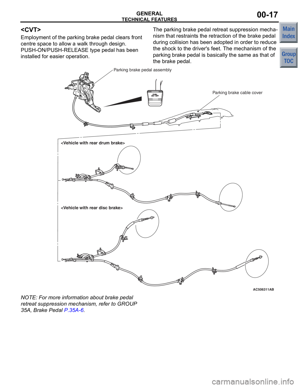
Employment of the parking brake pedal clears front
centre space to allow a walk through design.
PUSH-ON/PUSH-RELEASE type pedal has been
installed for easier operation.
The parking brake pedal retreat suppression mecha-
nism that restraints the retraction of the brake pedal
during collision has been adopted in order to reduce
the shock to the driver's feet. The mechanism of the
parking brake pedal is basically the same as that of
the brake pedal.
AC506311AB
Parking brake cable cover
Parking brake pedal assembly
NO TE: For more informatio n about brake peda l
retreat suppre ssion mech anism, refer to GROUP
35A, Brake Pedal
P.35A-6.
Page 214 of 364

TECHNICAL FEATURES
GENERAL00-29
IMPROVED SERVICEABILITY
•Employment of an automatic hydraulic timing belt
tensioner offers timing belt reliability, reduced
operating noise, and better serviceability. <4G1>
•Wiring harness section of the crank angle sensor
has been moulded integrally with the timing belt
cover, improving serviceability and reliability.
<4G1>
•Due to the adoption of the timing chain and the
timing chain tensioner, maintenance-free and reli
-
ability have been improved. <4A9>
•Since adoption of unvolatile memory (EEPROM*)
helps the learned value not to be initialised when
the battery terminal or connector of the control
unit is disconnected, maintainability can be
improved.
NOTE: *EEPROM: Electrical Erasable Programma-
ble ROM (information to be memorised can be
electronically written into and erased from ROM)
•Since the adoption of electric power steering
makes hydraulic pipes and oil pumps unneces
-
sary, maintainability can be improved.
•Employment of operative A/C piping layout and
refrigerant leak detection system enhances serv
-
iceability.
Page 291 of 364

CUSTOMISE FUNCTION
SMART WIRING SYSTEM (SWS)54B-25
CUSTOMISE FUNCTION
M2541006000243
Using M.U.T.-III adjusts the following function. The
programmed information is held even when the bat
-
tery is disconnected.
•Vehicle speed-dependent wiper function
With the windshield wiper switch in the intermittent
position, the intermittent duration changes
depending on the intermittent adjusting knob
position and the vehicle speed.
•The selector "P" position-linked central door
unlocking function
When the selector lever is shifted to the "P" position,
all the doors unlock.
•Turn-signal lamp operation sound function
Synchronized with the hazard lamp and the turn sig-
nal lamp, the buzzer sounds.
•Dimmer interior lamp control duration
When the door is closed with the ignition switch
LOCK (OFF), the interior lamp is turned OFF
automatically in the specified time.
•Timer lock time after executing the keyless entry
unlock
If any door including a tailgate is not opened after
being unlocked with the keyless transmitter,
doors are locked automatically within the speci
-
fied time.
•Door-ajar warning function
Driving with any door, including a tailgate, not prop-
erly closed sounds the buzzer to let the driver
know the door-ajar state.
•Rear wiper intermittent duration
When the rear wiper switch is turned ON, the rear
wiper operates in the intermittent action. When
the rear wiper switch is turned from OFF to ON
two cycles, the rear wiper makes continuous
operation regardless of the intermittent operation
duration setting.
•Wiper linked with washer function
When this function is active, the windshield wiper
operates if the washer switch is turned ON.
•Hazard answer back function of the keyless entry
system
When lock/unlock is operated with the keyless entry
transmitter, the horn sounds so that the driver can
recognize the lock/unlock status of the vehicle
even if the driver is away from it.
•Initialising all functions (Returning to the initial
condition)
All adjusting functions are returned to the settings at
the time of factory shipment.
Item
No.Items shown
on M.U.T.-III
screenItemAdjustment items
shown on M.U.T.-III
screenAdjusting contents
4SPEED SEN
WIPVehicle
speed-dependent
wiper functionW.FUNCTIONWith function (Initial setting)
W/O FUNCTIONWithout function
9KEYLESS(HA
ZD)Hazard answer
back function of
the keyless entry
systemLOCK/UNLOCKWith function for lock/unlock (the initial
condition)
LOCKEDWith function only for lock
UNLOCKEDWithout function only for unlock
W/O FUNCTIONWithout function
14P UNLOCK
ACT.Door unlock
function linked
with "P" position
shift for centre
door lock systemW.FUNCTIONWith function
W/O FUNCTIONWithout function (the initial condition)
15T/SIG.BUZZE
RTurn-signal lamp
operation sound
functionW.FUNCTIONWith function
W/O FUNCTIONWithout function (the initial condition)
Page 296 of 364
GENERAL INFORMATION
SUPPLEMENTAL RESTRAINT SYSTEM (SRS)52B-4
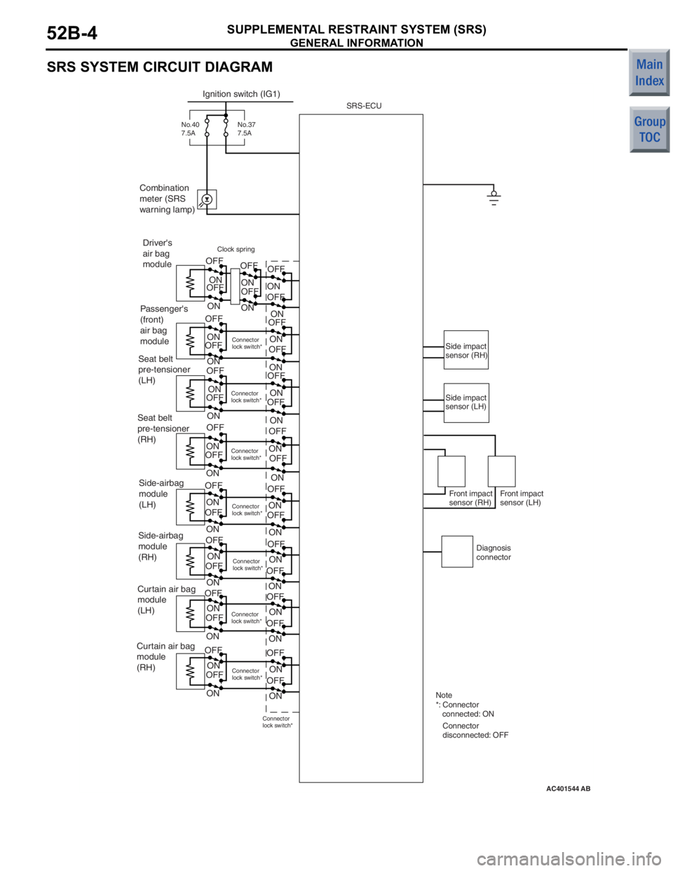
SRS SYSTEM CIRCUIT DIAGRAM
AC401544
Ignition switch (IG1)
Combination
meter (SRS
warning lamp)
No.40
7.5A
Driver's
air bag
module ON
OFF OFF
ON ON
OFF
ON
OFF
ON
ON
OFF
Passenger's
(front)
air bag
moduleClock spring
ON
OFF
OFF ON
OFF ON
OFF
ON
OFF
ON
ON
OFF
ON
ON
OFF
ON
OFF
ON
OFF
ON
OFF
ON
OFF
ON
OFF
Connector
lock switch*
Connector
lock switch* Connector
lock switch*Connector
lock switch*
Seat belt
pre-tensioner
(LH)
Seat belt
pre-tensioner
(RH)
Side-airbag
module
(LH)
Side-airbag
module
(RH)
Curtain air bag
module
(LH)
Curtain air bag
module
(RH) ON
OFF
OFF ON
ON
OFF
ON
ON
OFF
OFFONON
OFF
OFFON
OFF
ON
Connector
lock switch*
Connector
lock switch* Connector
lock switch*
OFFON
OFF
Connector
lock switch*Side impact
sensor (RH)
Side impact
sensor (LH)
Diagnosis
connector
Front impact
sensor (RH)
Front impact
sensor (LH)
Note
*: Connector
connected: ON Connector
disconnected: OFF
AB
SRS-ECU
ON
OFF
ON
OFF
ON
OFF
ON
OFF
OFF
ON
OFF OFF
No.37
7.5A