disc MITSUBISHI COLT 2006 Service User Guide
[x] Cancel search | Manufacturer: MITSUBISHI, Model Year: 2006, Model line: COLT, Model: MITSUBISHI COLT 2006Pages: 364, PDF Size: 11.65 MB
Page 306 of 364

SYSTEM CONSTRUCTION
SUPPLEMENTAL RESTRAINT SYSTEM (SRS)52B-14
DIAGNOSIS CODE SET
The SRS-ECU diagnoses the following items and
stores a diagnosis code in the non-volatile memory
(EEPROM*1) when a problem is detected. There
-
fore, the memory is not deleted after a battery termi-
nal is disconnected. (The diagnosis code memory
can be deleted by the M.U.T.-III).
CODE NO.MAJOR CONTENTS OF DIAGNOSTICS
1AFront impact sensor LH systemShort circuit in the sensor
1BOpen circuit in the sensor
1CShort circuit in the power supply
1DShort circuit in the earth
2AFront impact sensor RH systemShort circuit in the sensor
2BOpen circuit in the sensor
2CShort circuit in the power supply
2DShort circuit in the earth
3A*3Curtain air bag squib (RH) short-circuited
3B*3Curtain air bag squib (RH) open-circuited
3CCurtain air bag squib (RH) activating circuit short-circuited
3DCurtain air bag squib (RH) activating circuit open-circuited
3ECurtain air bag squib (RH) drive circuit (power supply side) short-circuited
3FCurtain air bag squib (RH) drive circuit (earth side) short-circuited
4A*3Curtain air bag squib (LH) short-circuited
4B*3Curtain air bag squib (LH) open-circuited
4CCurtain air bag squib (LH) activating circuit short-circuited
4DCurtain air bag squib (LH) activating circuit open-circuited
4ECurtain air bag squib (LH) drive circuit (power supply side) short-circuited
4FCurtain air bag squib (LH) drive circuit (earth side) short-circuited
14Analog G-sensor malfunction
15Safing G-sensor short-circuited (for frontal collision)
16Safing G-sensor open-circuited (for frontal collision)
17Safing G-sensor malfunction (for side collision)
21*3Driver's air bag squib short-circuited
22*3Driver's air bag squib open-circuited
24*3Passenger's (front) air bag squib short-circuited
25*3Passenger's (front) air bag squib open-circuited
26*3Driver's pre-tensioner squib short-circuited
27*3Driver's pre-tensioner squib open-circuited
28*3Passenger's (front) pre-tensioner squib short-circuited
29*3Passenger's (front) pre-tensioner squib open-circuited
31SRS-ECU capacitor circuit voltage too high
Page 310 of 364
SYSTEM CONSTRUCTION
SUPPLEMENTAL RESTRAINT SYSTEM (SRS)52B-18
SQUIB CIRCUIT CONNECTOR LOCK
SWITCH
AC300257
OFFON
OFF ON
Squib
SRS-ECU
A
A
ECU-side connectorB
B
AC
Section B - B
Section A - A
Connector connected
OFF
ON
OFF
ON
Squib
SRS-ECU
Connector disconnected
Terminal
(male)
Partition panelTerminal
(female) Short spring
Wiring harness-side connector
Terminal
(male)
Partition panel Terminal
(female)
Short spring Connector connected
Terminal
(male)
Partition panelTerminal
(female)
Short spring
Diagnosis spring
Diagnosis
spring
CAUTION
When the connector is disconnected, it is normal
for short-circuiting to occur between the connec
-
tor terminals.
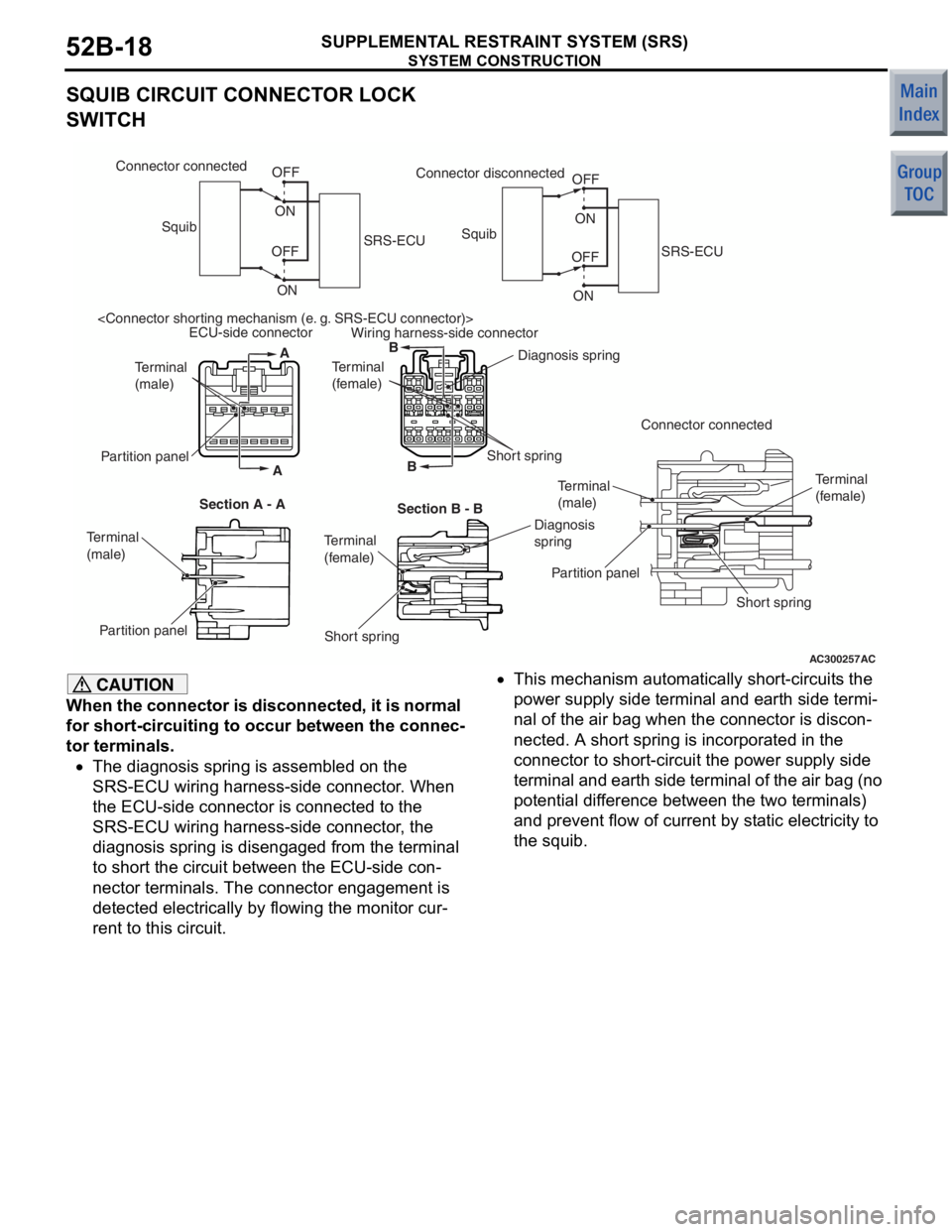
•The diagnosis spring is assembled on the
SRS-ECU wiring harness-side connector. When
the ECU-side connector is connected to the
SRS-ECU wiring harness-side connector, the
diagnosis spring is disengaged from the terminal
to short the circuit between the ECU-side con
-
nector terminals. The connector engagement is
detected electrically by flowing the monitor cur
-
rent to this circuit.
•This mechanism automatically short-circuits the
power supply side terminal and earth side termi
-
nal of the air bag when the connector is discon-
nected. A short spring is incorporated in the
connector to short-circuit the power supply side
terminal and earth side terminal of the air bag (no
potential difference between the two terminals)
and prevent flow of current by static electricity to
the squib.
Page 342 of 364

GENERAL INFORMATION
BASIC BRAKE SYSTEM35A-2
GENERAL INFORMATION
M2350000100848
FEATURES
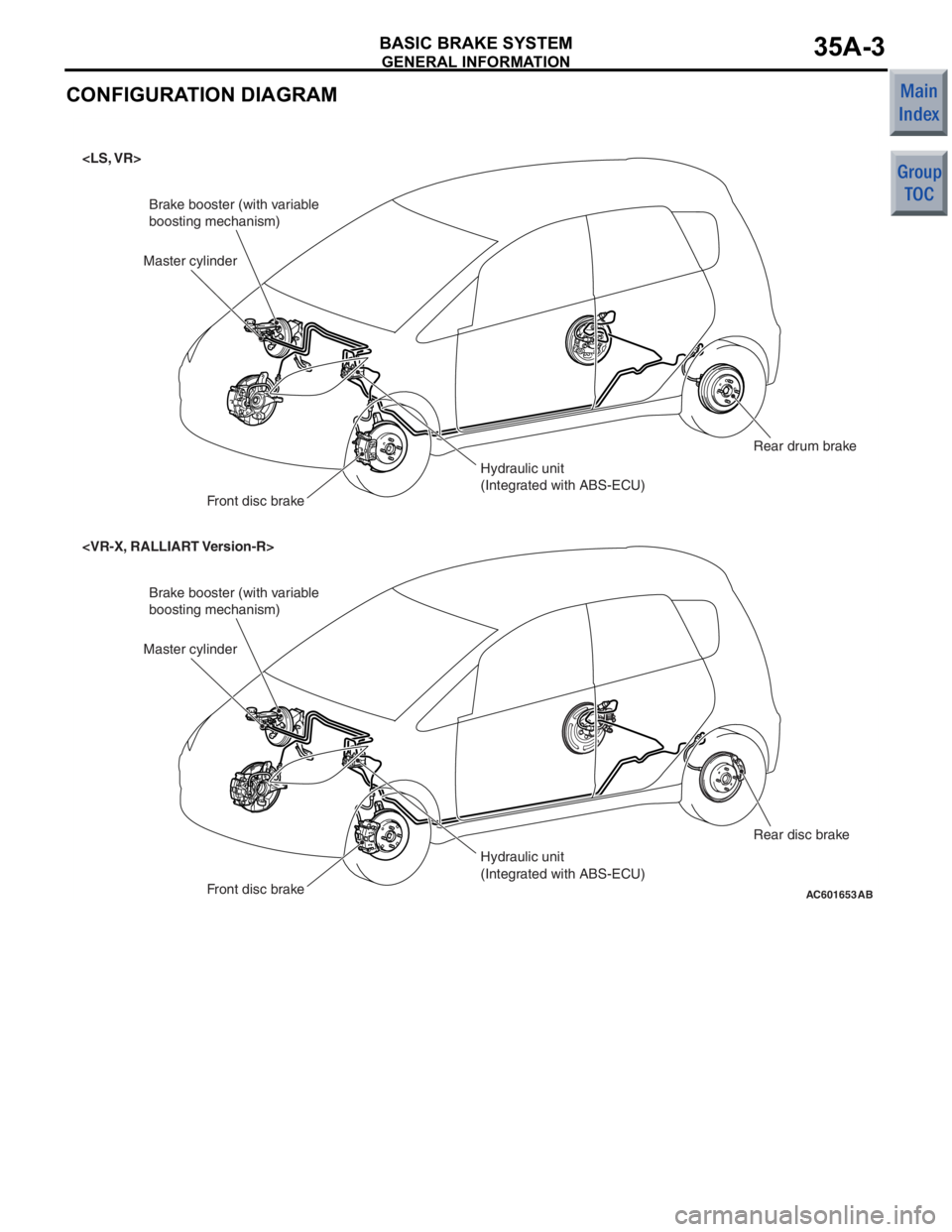
Brake system with high reliability and durability have
achieved distinguished braking performance.
BRAKING PERFORMANCE
•Brake booster with 9-inch variable amplification
ratio mechanism by which greater braking force
can be obtained with a less pedal pressure has
been installed (with brake assist function).
•14-inch disc brake is installed on the front
wheels.
•15-inch disc brake is installed on the front
wheels.
•8-inch leading trailing type drum brake is installed
on the rear wheels.
•14-inch disc brake is installed on the rear wheels.
STABILITY
•4-wheel anti-lock braking system (4ABS) is
adopted to prevent slipping caused by the vehicle
wheels locking up, in order to maintain appropri
-
ate braking distance, and also to maintain vehicle
stability and steering function.
•Electronic brake-force distribution (EBD) is
adopted to maintain the maximum amount of rear
braking force even when the vehicle's load is var
-
ied.
•Diagonal split (X-type) brake fluid line is adopted.
•Ventilated discs have been adopted to front
brakes to improve anti-fading performance.
•A brake pedal retraction suppression structure
that restrains the retraction of the brake pedal
and reduces the shock to the feet of the driver in
the event of a frontal collision has been adopted.
SERVICEABILITY
•Diagnosis function is adopted for the ABS system
in order to make inspection easier.
•For the front disc brakes, brake disc separated
front hub is adapted to make removal and instal
-
lation easier.
•ABS-ECU and hydraulic unit have been inte-
grated to make them more compact and lighter.
Page 343 of 364
GENERAL INFORMATION
BASIC BRAKE SYSTEM35A-3
CONFIGURATION DIAGRAM
AC601653
Brake booster (with variable
boosting mechanism)
Hydraulic unit
(Integrated with ABS-ECU)
Master cylinder
Front disc brake Rear drum brake
Brake booster (with variable
boosting mechanism)
Hydraulic unit
(Integrated with ABS-ECU)
Master cylinder
Front disc brake Rear disc brake
AB
Page 344 of 364

GENERAL INFORMATION
BASIC BRAKE SYSTEM35A-4
SPECIFICATIONS
ItemSpecifications
Master cylinderTy p eTandem type
I.D. mmLS, VR20.6
VR-X22.2
RALLIART Version-R23.8
Brake boosterTy p eVacuum type, single
Effective dia. of power cylinder mm230
Boosting ratioLS, VR, VR-X6.0 (pedal pressure: 116 N)
7.0 (pedal pressure: 159 N)
RALLIART Version-R6.0 (pedal pressure: 87 N)
7.0 (pedal pressure: 125 N)
Rear wheel hydraulic control methodElectronic brake-force
distribution (EBD)
Front brakesTy p eLS, VRFloating caliper, 1 piston,
ventilated disc (V4-S51)
VR-X, RALLIART Version-RFloating caliper, 1 piston,
ventilated disc (V5-S54)
Disc effective dia. ×
thickness mmLS, VR206 × 20
VR-X226 × 24
RALLIART Version-R232 × 25.8
Cylinder I.D. mmLS, VR50.8
VR-X, RALLIART Version-R54.0
Pad thickness mmLS, VR, VR-X10
RALLIART Version-R10.5
Clearance adjustmentAutomatic
Rear disc brakes
Ty p eVR-XFloating caliper, 1 piston,
solid disc (S4-S30P)
RALLIART Version-RFloating caliper, 1 piston,
solid disc (S4-S34P)
Disc effective dia. ×
thickness mmVR-X224 × 10
RALLIART Version-R200.6 × 10
Cylinder I.D. mmVR-X30.2
RALLIART Version-R34.0
Pad thickness mmVR-X9.5
RALLIART Version-R10.0
Clearance adjustmentAutomatic
Rear drum brakes
Ty p eLeading trailing drum
Drum I.D. mm203
Cylinder I.D. mm19.0
Lining thickness mm4.0
Clearance adjustmentAutomatic
Brake fluidDOT3 or DOT4
Page 345 of 364
CONSTRUCTION DESCRIPTION
BASIC BRAKE SYSTEM35A-5
CONSTRUCTION DESCRIPTION
MASTER CYLINDERM2350001000509
AC505737ABMaster cylinder
Reserve tank
Primary piston
Secondary piston
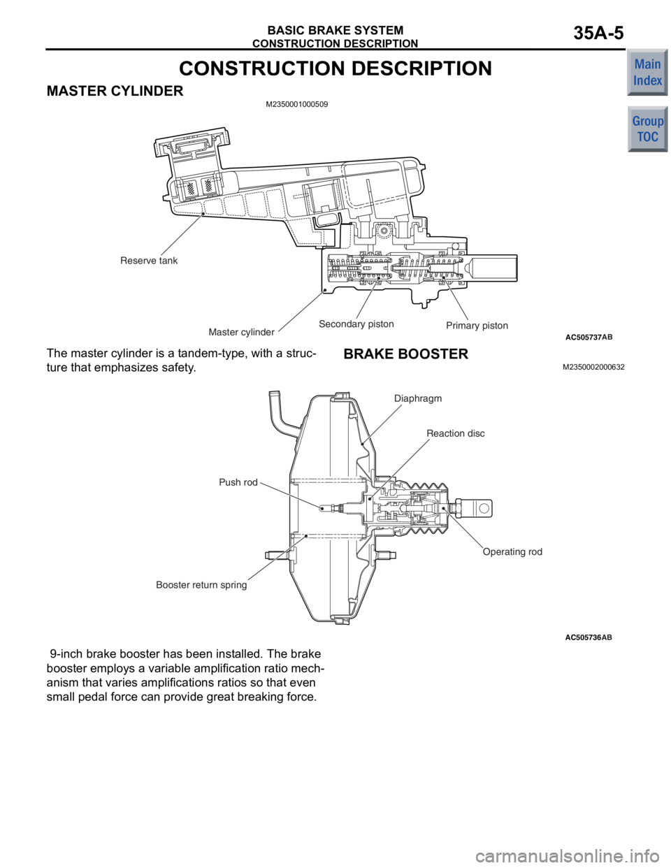
The master
cylind e r is a t andem-typ e, with a stru c-
ture that emp hasizes sa fety .
BRAKE BOOSTER
M23500020 0063 2
AC505736AB
Reaction disc
Booster return spring Push rod
Diaphragm
Operating rod
9-inch brake booste r has been inst alled. T he brake
booster employs a
variable amplification ratio mech
-
anism that va ries amplifications ratios so that e v en
sma
ll p edal force can provide gre a t brea kin g force.
Page 347 of 364
CONSTRUCTION DESCRIPTION
BASIC BRAKE SYSTEM35A-7
FRONT BRAKE
M2350003000538
AC403189AE
14-inch disc brake
15-inch disc brake
Brake disk
Wear indicator When new When worn
Conventional structure
Caliper support
bracket Knuckle
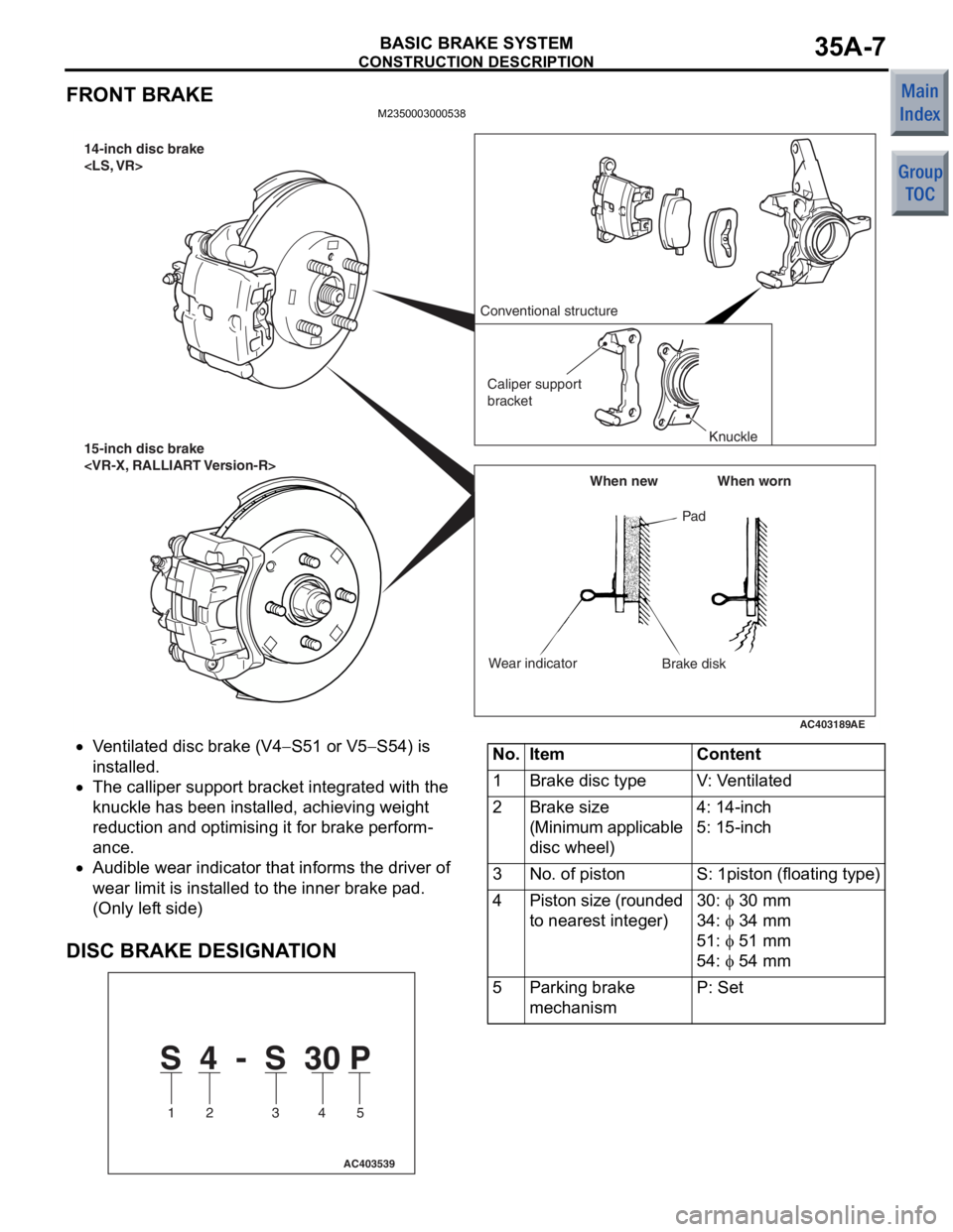
•Ventilate d disc b r ake (V4−S51 or V5−S54) is
in
st
alled.
•The callipe r sup port bra c ket int egrated with the
kn
uckle h a s be en in st alled, achie v in g weigh t
redu
ction and optimising it for b r ake perform
-
ance.
•Audible wear indicat o r that informs th e driver of
wear limit is inst
alle d to th e inn e r brake p ad.
(Only lef
t side)
DISC BRAKE DESIGNA T ION
S 4 - S 30 P
1 2 3 4 5
AC403539
No.ItemContent
1Brake disc typeV: Ventilated
2Brake size
(Minimum applicable
disc wheel)4: 14-inch
5: 15-inch
3No. of pistonS: 1piston (floating type)
4Piston size (rounded
to nearest integer)30: φ 30 mm
34: φ 34 mm
51: φ 51 mm
54: φ 54 mm
5Parking brake
mechanismP: Set
Page 348 of 364
CONSTRUCTION DESCRIPTION
BASIC BRAKE SYSTEM35A-8
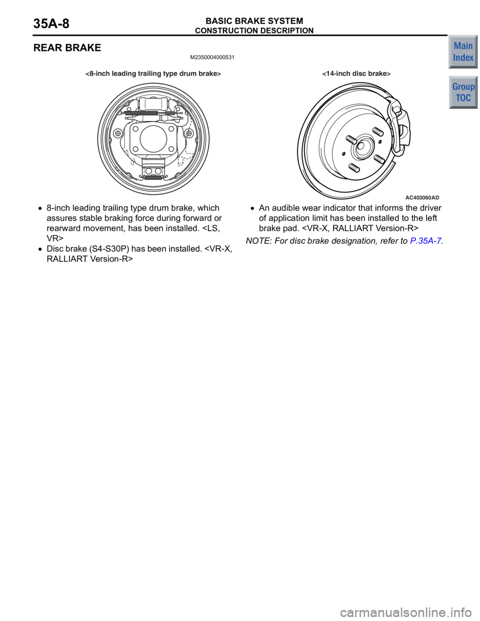
REAR BRAKE
M2350004000531
AC403060AD
<8-inch leading trailing type drum brake> <14-inch disc brake>
•8-inch leading tra iling type drum brake, which
assure
s st ab le bra k in g force during forward or
rearward
movement, ha s bee n inst alle d.
•Disc brake (S4 - S3 0 P ) ha s be en in st a l le d.
T V e rsion - R>
•An audible wear indicator th at in forms the d r ive r
of a
pplication limit has been inst a lled to the lef t
brake p
ad.
NOTE: For d i sc brake de sign ation , refer t o P.35A-7.
Page 351 of 364
CVT
CONTINUOUSLY VARIABLE TRANSMISSION (CVT)23-3
ELECTRONIC CONTROL SYSTEM
EEPROM
M2231012000024
Because EEPROM has been used, even if the bat-
tery terminals or control unit connectors are discon-
nected, the necessary learned values are stored in
the engine-CVT-ECU to prevent a loss of shift qual
-
ity. (Initialisation is available by M.U.T.-III).
CONTROLLER AREA NETWORK (CAN)
COMMUNICATION
M2231017000018
CAN* communication has been adopted for commu-
nication with other ECUs in order to decrease the
number of wires and ensure information transmis
-
sion. For CVT control, the engine-CVT-ECU receives
the following signals.
CAN COMMUNICATION INPUT SIGNAL TABLE
Input signalTransmitter ECU
Average vehicle speed signal from drive wheelsABS-ECU
Motor current signalEPS-ECU
EPS warning lamp illumination request signal
Compressor signalMeter and A/C-ECU
NOTE: *: For more information about CAN (Control-
ler Area Network), refer to GROUP 54C P.54C-2.
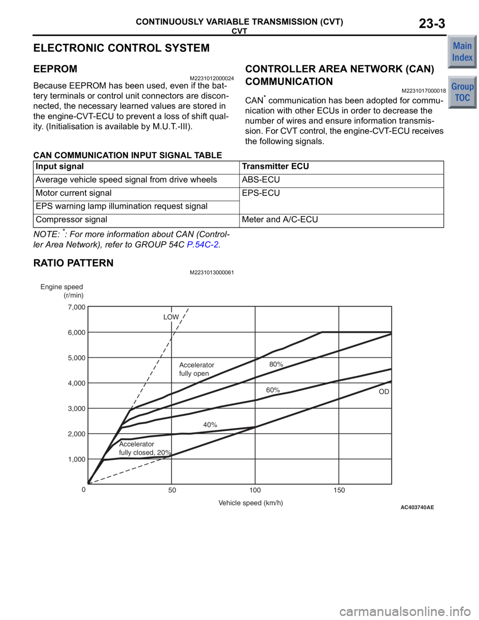
RATIO PATTERN
M2231013000061
AC403740
AE
Engine speed
(r/min)
Vehicle speed (km/h)
0
100 150
50
1,000 2,000 4,000
3,000 5,000
7,000
6,000
OD
LOW
Accelerator
fully closed, 20% 40%
Accelerator
fully open
60%80%