drive MITSUBISHI COLT 2006 Service Repair Manual
[x] Cancel search | Manufacturer: MITSUBISHI, Model Year: 2006, Model line: COLT, Model: MITSUBISHI COLT 2006Pages: 364, PDF Size: 11.65 MB
Page 2 of 364
GENERAL INFORMATION
ANTI-SKID BRAKE SYSTEM (ABS)35B-2
GENERAL INFORMATION
M2351000100409
FEATURES
The ABS ensures directional stability and controlla-
bility during hard braking.
For vehicles with this type of ABS, 4 sensors (4
channels) are installed on front and rear wheels
allowing independent left and right control.
The system has the following features:
•EBD (Electronic Brake-force Distribution system)
control has been added to provide the ideal brak
-
ing force for the rear wheels.
•Magnetic encoder for wheel speed detection has
been installed as a sensing device instead of the
rotor.
•For wiring harness saving and secure data com-
munication, CAN* bus has been adopted as a
tool of communication with another ECU.
NOTE: *: For more information about CAN (Control-
ler Area Network), refer to Group 54C, General Infor-
mation P.54C-2.
EBD CONTROL
In ABS, electronic control is used so the rear wheel
brake hydraulic pressure during braking is regulated
by rear wheel control solenoid valves in accordance
with the vehicle's rate of deceleration, and the front
and rear wheel slippage which are calculated from
the signals received from the various wheel speed
sensors. EBD control provides a high level of control
for both vehicle braking force and vehicle stability.
The system has the following features:
•Because the system provides the optimum rear
wheel braking force regardless of vehicle load
condition and the condition of the road surface,
the system reduces the required pedal depres
-
sion force, particularly when the vehicle is heavily
loaded or driven on road surfaces with high fric
-
tional coefficients.
•Because the duty placed on the front brakes is
reduced, the increase in pad temperature can be
controlled during brakes application to improve
the wear resistance characteristics of the pad.
•Control valves such as the proportioning valve
are not required.
SPECIFICATIONS
ItemSpecification
ABS control method4-sensor, 4-channel
Wheel speed
sensorMagnetic encoderFront86 (N pole:43 S pole:43)
Rear86 (N pole:43 S pole:43)
Ty p eSemiconductor
Page 3 of 364
GENERAL INFORMATION
ANTI-SKID BRAKE SYSTEM (ABS)35B-3
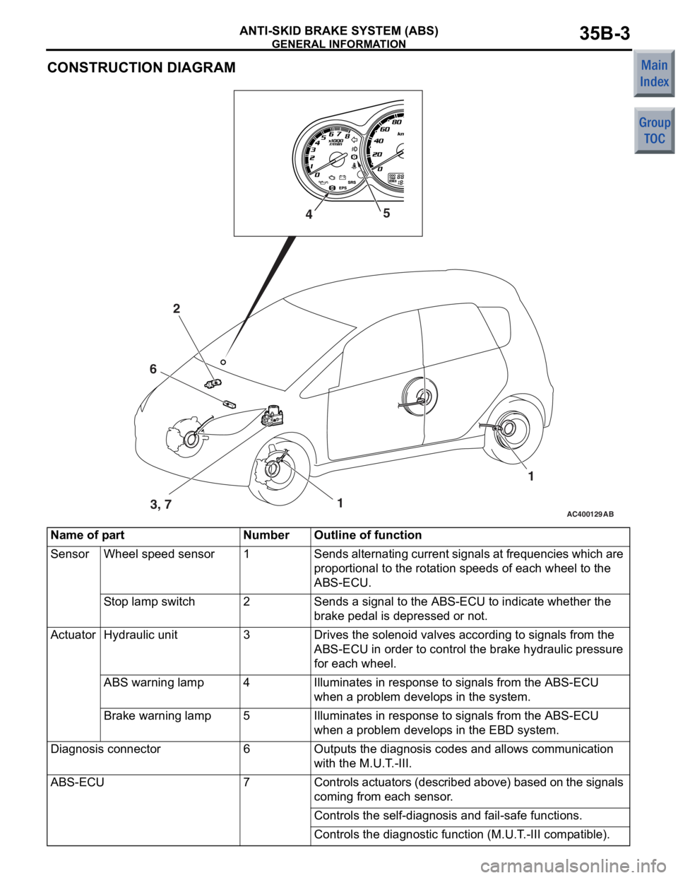
CONSTRUCTION DIAGRAM
AC400129AB1
2
3, 7 1
4
5
6
Name of partNumberOutline of function
SensorWheel speed sensor1Sends alternating current signals at frequencies which are
proportional to the rotation speeds of each wheel to the
ABS-ECU.
Stop lamp switch2Sends a signal to the ABS-ECU to indicate whether the
brake pedal is depressed or not.
ActuatorHydraulic unit3Drives the solenoid valves according to signals from the
ABS-ECU in order to control the brake hydraulic pressure
for each wheel.
ABS warning lamp4Illuminates in response to signals from the ABS-ECU
when a problem develops in the system.
Brake warning lamp5Illuminates in response to signals from the ABS-ECU
when a problem develops in the EBD system.
Diagnosis connector6Outputs the diagnosis codes and allows communication
with the M.U.T.-III.
ABS-ECU7Controls actuators (described above) based on the signals
coming from each sensor.
Controls the self-diagnosis and fail-safe functions.
Controls the diagnostic function (M.U.T.-III compatible).
Page 12 of 364
CONSTRUCTION DESCRIPTION
ANTI-SKID BRAKE SYSTEM (ABS)35B-12
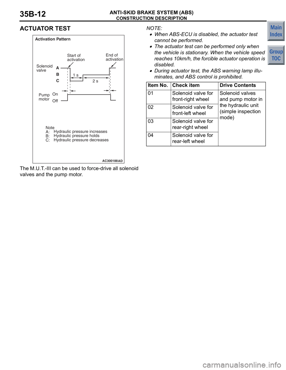
ACTUATOR TEST
AC300188AD
Activation PatternAB
C Start of
activation
1 s 2 s
On
Off
Note
A:
B:
C: Hydraulic pressure increases
Hydraulic pressure holds
Hydraulic pressure decreases End of
activation
Solenoid
valve
Pump
motor
The M.U.T . -III can be u s ed to force-drive a ll sole noid
valves and th
e pump mo tor .
NOTE: .
•Whe n ABS-ECU is disabled, the actu ator te st
cannot b
e perfo rmed.
•The actu ator test can be p e rformed on ly whe n
the
veh i cle is st a t iona ry . Whe n the ve hicle speed
rea
c h e s 10km/h, the f o rcible a c t uator operation is
disabled.
•During actuator test, the ABS warning lamp illu-
minates , an d ABS contro l is proh ibit ed.
Item No.Check itemDrive Contents
01Solenoid valve for
front-right wheelSolenoid valves
and pump motor in
the hydraulic unit
(simple inspection
mode)
02Solenoid valve for
front-left wheel
03Solenoid valve for
rear-right wheel
04Solenoid valve for
rear-left wheel
Page 22 of 364
AC206998AB
Wiper blade (RH)
(650 mm)Wiper blade (LH)
(300 mm)
WIPE
R AN D W A SHER
EXTERIOR51-10
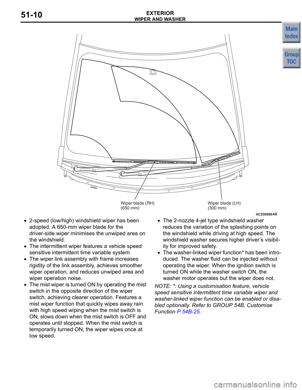
•2-speed (low/high) wind shield wip e r has been
ado
pted. A 6 50-mm wipe r blad e for th e
driver-side
wiper minimises the unwiped are a on
the
windshield.
•The intermitte nt wipe r feature s a vehicle spe ed
se
nsitive inte rmit tent time varia b le system.
•The wiper link assemb ly with frame in creases
rig
i dit y of t he link a s sembly , achieves smo o ther
wipe
r operat ion, a nd red u ces unwip ed area and
wipe
r operat ion n o ise.
•The mist wip e r is tu rned ON by o pera t ing the mist
switch in the
opposite direction of the wiper
switch,
achieving cleare r operat ion. F eatures a
mist wiper fun
c tio n that quickly wipe s away rain
with
high spee d wiping when t he mist switch is
ON,
slows down whe n th e mist switch is OFF and
ope
rates until sto pped. When th e mist switch is
temporarily turned
ON, the wiper wip e s o n ce a t
lo
w speed .
•The 2-nozzle 4-je t type windshield wash er
redu
ces the varia t ion of the spla shing point s on
the
windshield while dr iving at high speed. The
wind
shield washer secu res h i gher driver ’ s visibil
-
ity for impro v ed safe ty .
•The washer-linke d wiper function * has b een int r o-
duced. The wash er flu i d can be injected withou t
ope
rating the wip e r . Whe n the ignition switch is
turn
ed ON while t he wash er switch ON, the
washer mo
tor ope rates but th e wiper d oes not.
NOTE: *: Using a cust omisation fea t ure, vehicle
spee
d sen s it ive intermitte nt time variab le wip e r and
wa
sher
-lin ked wiper fun c tio n ca n be e nable d or disa
-
bled optio nally . Refer to GROUP 54 B, Cu stomise
Funct
i on
P.54B-25.
Page 35 of 364
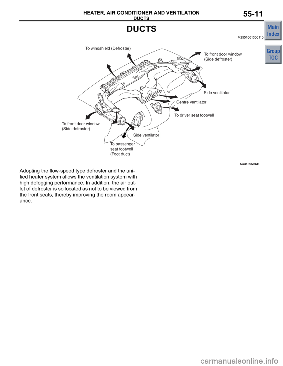
DUCTS
HEATER, AIR CONDITIONER AND VENTILATION55-11
DUCTS
M2551001300110
AC313959AB
To windshield (Defroster)To front door window
(Side defroster)
Side ventilator
Side ventilator Centre ventilator
To passenger
seat footwell
(Foot duct)
To front door window
(Side defroster)
To driver seat footwell
Ad
optin g the f l ow-sp eed type de froste r and th e uni-
fied heate r syst em allows th e ventilation system with
high
defogg ing p e rformance . In ad dition, the air ou t
-
let of defroster is so located as no t to be vie w e d from
the fron
t sea t s, there b y impro v ing the ro om ap pear
-
ance.
Page 57 of 364
BASE ENGINE
ENGINE MECHANICAL <4A9>11A-9
CRANKSHAFT
AK305068AD
Oil pump drive
gear shaft
Crankshaft
sprocket
Crankshaft sensing ring
CrankshaftOil hole
Oil hole
Balance weightBalance weightBalance weight
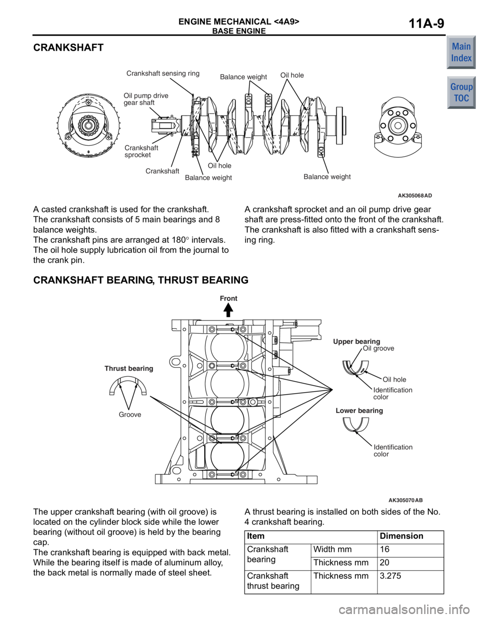
A casted crankshaf
t is used for t he cr ankshaf t.
The crankshaft consist s o f 5 ma in be aring s an d 8
balan
ce weight s.
The crankshaft pins a r e arrang ed at 1 8 0° inte rval s.
The oil hole supply lu brication oil from t he jo urnal to
the crank p
i n.
A cranksha f t sprocket and an oil pump drive gea r
shaf
t are press-fit t ed on to the f r ont of the crankshaf t.
The crankshaft is also fitt ed with a crankshaf t sens-
ing ring.
CRANKSHAFT BEARING, THRUST BEARING
AK305070
Upper bearingOil groove
Oil hole
Identification
color
Lower bearing
Identification
color
AB
Thrust bearing
Groove
Front
The upp er cra n kshaf t bea ring (with oil groove) is
loca
ted on the cylinder block side wh ile the lo we r
bearin
g (witho ut oil groo ve) is he ld by the b earin g
cap.
The crankshaft bea ring is e quipp ed with back me t a l.
While the b
earin g it self is ma de of a l uminum alloy ,
the back met
a l is no rmally made of steel sheet .
A thrust bearing is inst alle d on b o th sides of th e No.
4 cran
kshaf t bearing.
ItemDimension
Crankshaft
bearingWidth mm16
Thickness mm20
Crankshaft
thrust bearingThickness mm3.275
Page 58 of 364
BASE ENGINE
ENGINE MECHANICAL <4A9>11A-10
CRANKSHAFT PULLEY
AK305072AD
Timing markDamper
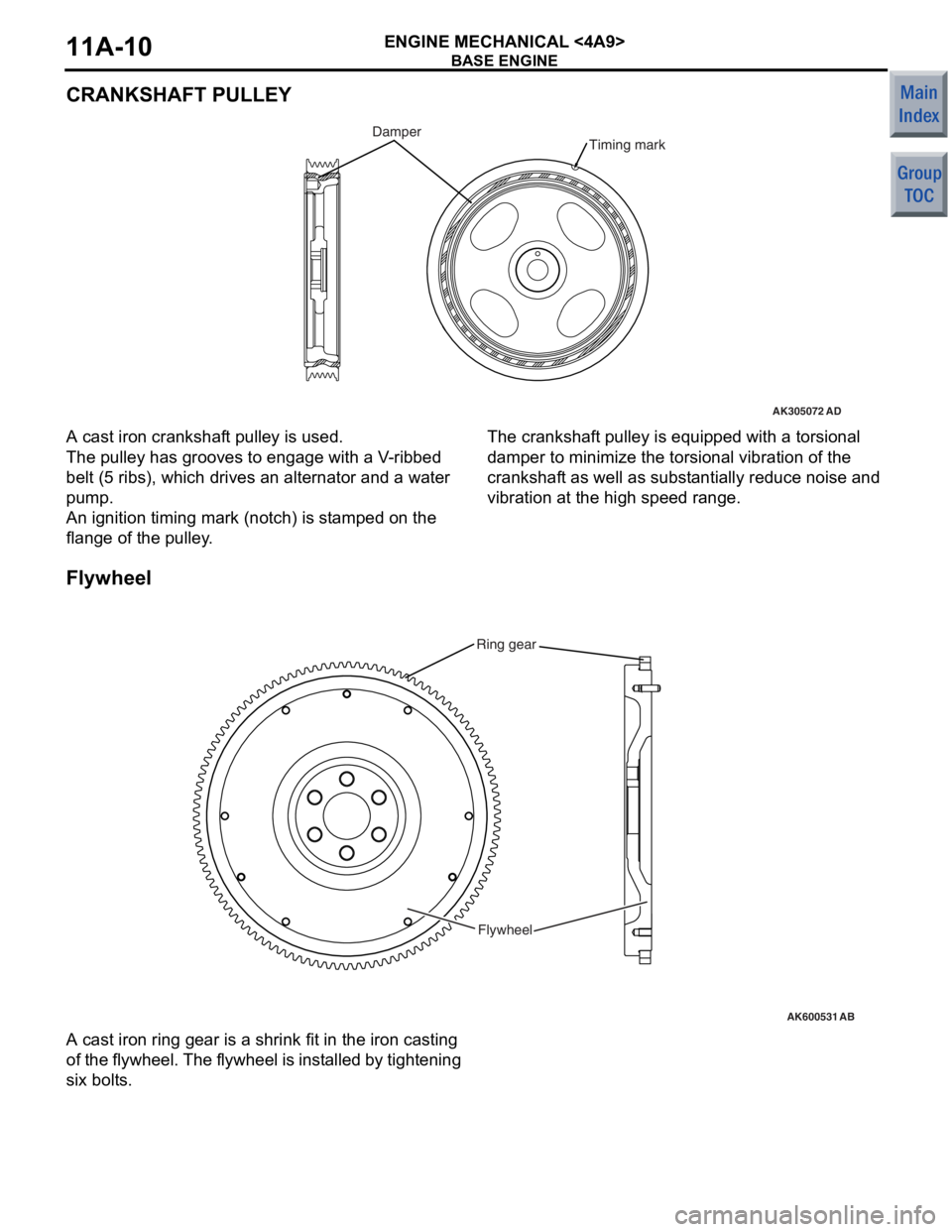
A cast iron cranksh af t pulley is used.
The pulley has grooves to eng age with a V -rib bed
belt (5
ribs), which drives an alternat or and a water
pump
.
An ignition timing mark (notch) is st amp ed on the
flang
e of the pulley .
The crankshaft pulley is equipped with a to rsio nal
damp
e r to minimize the torsional vibratio n of th e
cranksha
f t as well as sub s t antia lly redu ce no ise and
vib
r ation at the high spee d rang e.
Flyw he el
AK600531
Ring gear
Flywheel
AB
A cast iron ring g ear is a shrink fit in th e iron casting
of
t h e f l yw he el. T h e f l yw he el is in st a l le d by tigh t e n i n g
six bolt
s .
Page 59 of 364
BASE ENGINE
ENGINE MECHANICAL <4A9>11A-11
DRIVE PLATE
AK401856Ring gearDrive plateAB
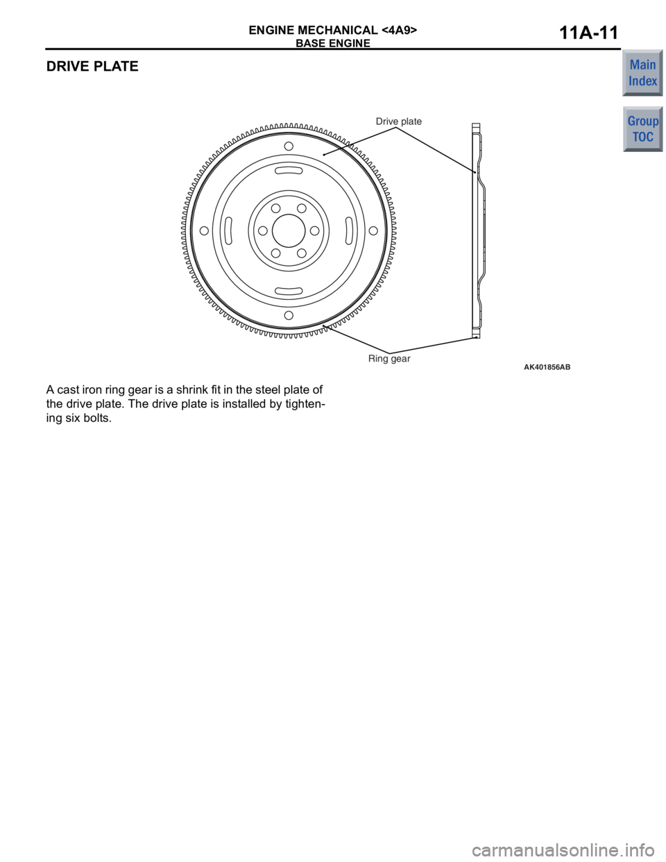
A cast iron
ring g ear is a shrin k fit in th e ste e l plate o f
the drive p
l ate. The drive p l ate is inst alled b y tighten
-
ing six bolts .
Page 60 of 364
BASE ENGINE
ENGINE MECHANICAL <4A9>11A-12
TIMING CHAIN TRAIN
AK305075
V.V.T. sprocket
AB
V.V.T. sprocket
timing mark
Timing chain mark
link plate (bule)
Camshaft sprocket
Camshaft sprocket
timing mark Timing chain mark
link plate (bule)
Timing chain mark
link plate (bule)
Crankshaft
sprocket
timing mark
Crankshaft sprocket
Timing mark
Timing chain
tensioner
Tensioner lever
Chain guide
Timing mark
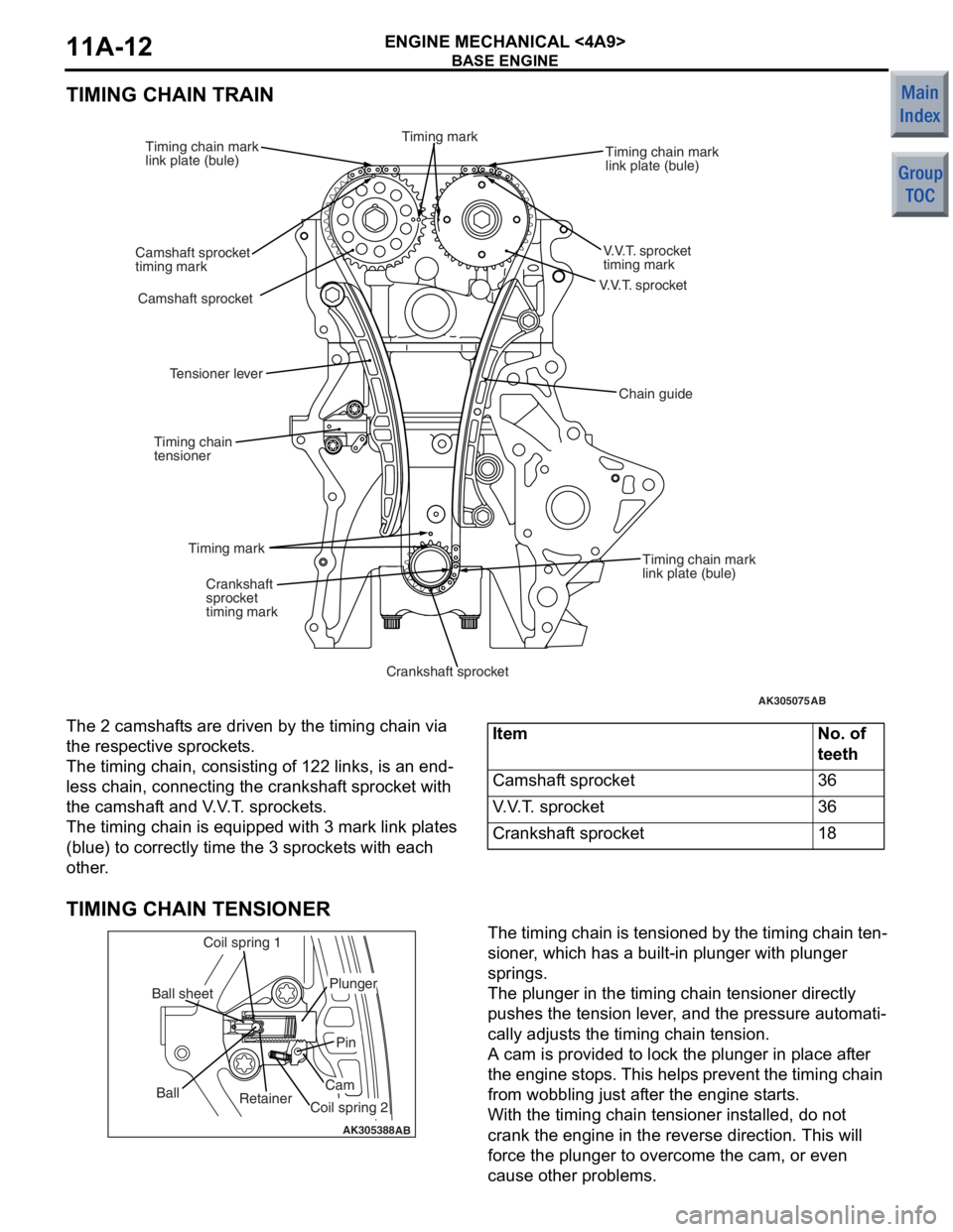
The 2 camshaf
t s are driven by the t i ming chain via
the res
pec tive spro cke t s .
The timing cha i n, consist i ng o f 122 links, is an end-
less chain, conn ecting the cran ksh af t spro cke t with
the camshaf
t and V . V . T . spro cke t s .
The timing cha i n is eq uippe d with 3 mark link p l ates
(blue)
to co rrectly time t he 3 sprocket s with each
other
.
ItemNo. of
teeth
Camshaft sprocket36
V.V.T. sprocket36
Crankshaft sprocket18
TIMING CHAIN TENSIONER
AK305388AB
Retainer
Ball
Coil spring 1
Ball sheet
Coil spring 2
Cam
Pin
Plunger
The timing chain is tensione
d by th e timing chain te n-
sioner , which ha s a b u ilt-in plunge r with plunge r
springs.
The plunger in the timing chain tension e r dire ctly
push
e s th e tension lever , and the pre s sure aut omati
-
cally ad just s the timing chain tension.
A cam is provided t o lock th e plu nger in pla c e a f te r
the eng
ine stop s. This help s prevent the timing chain
from wob
b lin g just af ter th e eng ine st a r t s .
With the timing cha i n ten s io ner in st alled, do not
crank the
engin e in the reverse directio n. This will
force
the plunger to overcome the cam, or e v en
cause oth
e r problems.
Page 73 of 364
BASE ENGINE
ENGINE MECHANICAL <4A9>11A-25
CRANKSHAFT
AK305068AD
Oil pump drive
gear shaft
Crankshaft
sprocket
Crankshaft sensing ring
CrankshaftOil hole
Oil hole
Balance weightBalance weightBalance weight
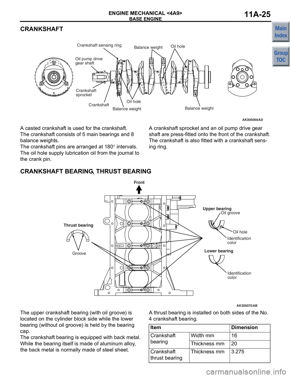
A casted crankshaf
t is used for t he cr ankshaf t.
The crankshaft consist s o f 5 ma in be aring s an d 8
balan
ce weight s.
The crankshaft pins a r e arrang ed at 1 8 0° inte rval s.
The oil hole supply lu brication oil from t he jo urnal to
the crank p
i n.
A cranksha f t sprocket and an oil pump drive gea r
shaf
t are press-fit t ed on to the f r ont of the crankshaf t.
The crankshaft is also fitt ed with a crankshaf t sens-
ing ring.
CRANKSHAFT BEARING, THRUST BEARING
AK305070
Upper bearingOil groove
Oil hole
Identification
color
Lower bearing
Identification
color
AB
Thrust bearing
Groove
Front
The upp er cra n kshaf t bea ring (with oil groove) is
loca
ted on the cylinder block side wh ile the lo we r
bearin
g (witho ut oil groo ve) is he ld by the b earin g
cap.
The crankshaft bea ring is e quipp ed with back me t a l.
While the b
earin g it self is ma de of a l uminum alloy ,
the back met
a l is no rmally made of steel sheet .
A thrust bearing is inst alle d on b o th sides of th e No.
4 cran
kshaf t bearing.
ItemDimension
Crankshaft
bearingWidth mm16
Thickness mm20
Crankshaft
thrust bearingThickness mm3.275