fuel pump MITSUBISHI COLT 2006 Service Repair Manual
[x] Cancel search | Manufacturer: MITSUBISHI, Model Year: 2006, Model line: COLT, Model: MITSUBISHI COLT 2006Pages: 364, PDF Size: 11.65 MB
Page 97 of 364
GENERAL INFORMATION
MULTIPOINT FUEL INJECTION (MPI) <4A9>13A-3
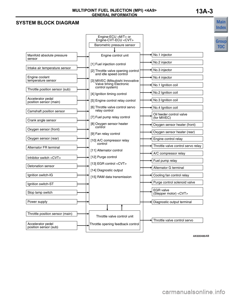
SYSTEM BLOCK DIAGRAM
AK600486
Barometric pressure sensorThrottle valve control servo
Manifold absolute pressure
sensor
Engine coolant
temperature sensor
No.1 injector
No.2 injector
No.3 injector
No.4 injector
No.1 Ignition coil
No.2 Ignition coil
No.3 Ignition coil
No.4 Ignition coil
Engine control relay
Throttle valve control servo relay
A/C compressor relay
Fuel pump relay
Alternator G terminal
Cooling fan control relay
Purge control solenoid valve
Diagnostic output terminal
Intake air temperature sensor
Accelerator pedal
position sensor (main) Throttle position sensor (sub)
Camshaft position sensor
Crank angle sensor
Oxygen sensor (front)
Oxygen sensor (rear)
Alternator FR terminal
Inhibitor switch
Detonation sensor
Ignition switch-IG
Ignition switch-ST
Stop lamp switch
Power supply
Accelerator pedel
position sensor (sub) Throttle position sensor (main)
Throttle valve control unitEngine control unit
Engine-ECU
Engine-CVT-ECU
Throttle opening feedback control Oxygen sensor heater (front)
Oxygen sensor heater (rear)
[1] Fuel injection control
[2] Throttle valve opening control
and idle speed control
[3] MIVEC (Mitsubishi Innovative
Valve timing Electronic
control system)
[4] Ignition timing control
[5] Engine control relay control
[6] Throttle valve control servo
relay control
[7] Fuel pump relay control
[8] Oxygen sensor heater
control
[9] Fan relay control
[10] A/C compressor relay
control
[11] Alternator control
[12] Purge control
[13] EGR control
[14] Diagnostic output
[15] RAM data transmission
Oil feeder control valve
(for MIVEC)
EGR valve
(Stepper motor)
AB
Page 98 of 364
GENERAL INFORMATION
MULTIPOINT FUEL INJECTION (MPI) <4A9>13A-4
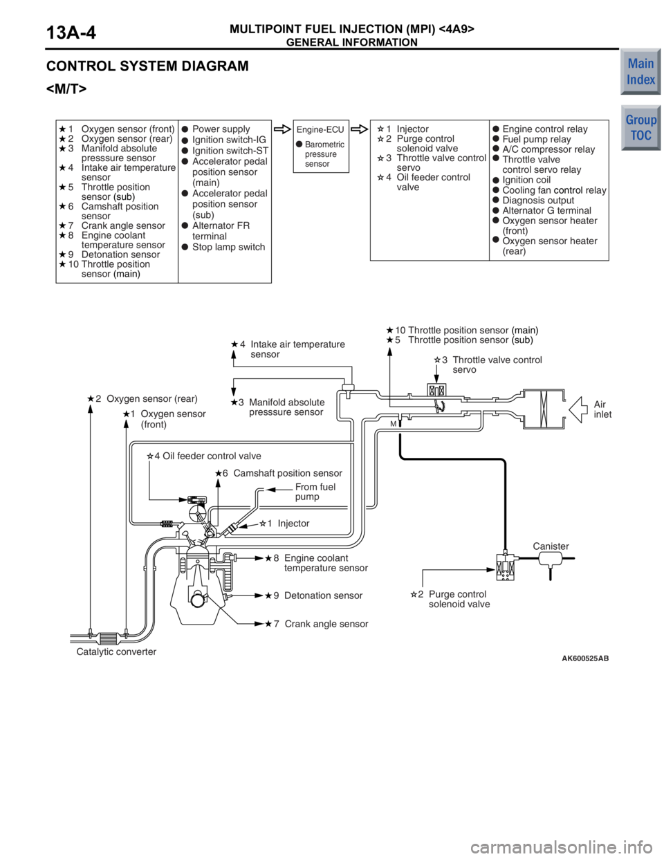
CONTROL SYSTEM DIAGRAM
AK600525
1 Oxygen sensor
(front)4 Intake air temperature
sensor
3 Manifold absolute
presssure sensor
2 Oxygen sensor (rear) 3 Throttle valve control
servo
10 Throttle position sensor
(main)
2 Purge control
solenoid valve
8 Engine coolant
temperature sensor
9 Detonation sensor
7 Crank angle sensor
6 Camshaft position sensor
4 Oil feeder control valve
1 Injector
AB
M
1 Oxygen sensor (front)
2 Oxygen sensor (rear)
3 Manifold absolute
presssure sensor
4 Intake air temperature
sensor
5 Throttle position
sensor
(sub)
6 Camshaft position
sensor
7 Crank angle sensor
8 Engine coolant
temperature sensor
9 Detonation sensor
10 Throttle position
sensor (main) 1 Injector
2 Purge control
solenoid valve
3 Throttle valve control
servo
4 Oil feeder control
valve
Power supply
Ignition switch-IG
Ignition switch-ST
Accelerator pedal
position sensor
(main)
Accelerator pedal
position sensor
(sub)
Alternator FR
terminal
Stop lamp switchEngine-ECUEngine control relay
Fuel pump relay
A/C compressor relay
Throttle valve
control servo relay
Ignition coil
Cooling fan
control relay
Diagnosis output
Alternator G terminal
Oxygen sensor heater
(front)
Oxygen sensor heater
(rear)
Canister Air
inlet
Catalytic converter From fuel
pump
5 Throttle position sensor
(sub)
Barometric
pressure
sensor
Page 99 of 364
GENERAL INFORMATION
MULTIPOINT FUEL INJECTION (MPI) <4A9>13A-5
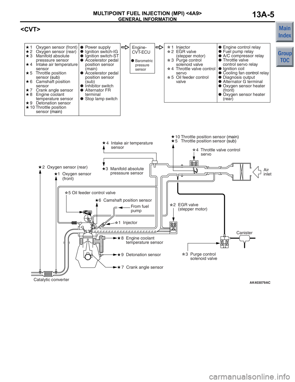
AK403079
1 Oxygen sensor
(front)4 Intake air temperature
sensor
3 Manifold absolute
presssure sensor
2 Oxygen sensor (rear) 4 Throttle valve control
servo
10 Throttle position sensor
(main)
2 EGR valve
(stepper motor) 3 Purge control
solenoid valve
8 Engine coolant
temperature sensor
9 Detonation sensor
7 Crank angle sensor
6 Camshaft position sensor
5 Oil feeder control valve
1 Injector
AC
1 Oxygen sensor (front)
2 Oxygen sensor (rear)
3 Manifold absolute
presssure sensor
4 Intake air temperature
sensor
5 Throttle position
sensor (sub)
6 Camshaft position
sensor
7 Crank angle sensor
8 Engine coolant
temperature sensor
9 Detonation sensor
10 Throttle position
sensor (main) 1 Injector
2 EGR valve
(stepper motor)
3 Purge control
solenoid valve
4 Throttle valve control
servo
5 Oil feeder control
valve
Power supply
Ignition switch-IG
Ignition switch-ST
Accelerator pedal
position sensor
(main)
Accelerator pedal
position sensor
(sub)
Inhibitor switch
Alternator FR
terminal
Stop lamp switchEngine-
CVT-ECUEngine control relay
Fuel pump relay
A/C compressor relay
Throttle valve
control servo relay
Ignition coil
Cooling fan
control relay
Diagnosis output
Alternator G terminal
Oxygen sensor heater
(front)
Oxygen sensor heater
(rear)
Canister Air
inlet
Catalytic converter From fuel
pump
5 Throttle position sensor
(sub)
Barometric
pressure
sensor
Page 102 of 364

GENERAL INFORMATION
MULTIPOINT FUEL INJECTION (MPI) <4A9>13A-8
Fuel pump relayControls the power supplied to the fuel pump in
accordance with the signals received from the
engine-ECU
A/C compressor relayControls the operation of the A/C compressor in
accordance with the signals received from the
engine-ECU
Purge control solenoid valveControls the flow rate of the purge air introduced into
the inlet manifold in accordance with the signals
received from the engine-ECU
engine-CVT-ECU
EGR valve (stepper motor)
signals received from the engine-CVT-ECU.
Alternator G terminalControls the amount of current generated by the
alternator in accordance with the signals received
from the engine-ECU
Cooling fan control relayControls the rotation of cooling the fan in accordance
with the signals received from the engine-ECU
Throttle valve control servoControls the throttle valve position in accordance with
the signals received from the engine-ECU
engine-CVT-ECU
Oil feeder control valveThe oil feeder control valve, which is actuated by the
signals received from the engine-ECU
engine-CVT-ECU
Oxygen sensor heater
in accordance with the signals received from the
engine-ECU
Name Function
Page 103 of 364
FUEL INJECTION CONTROL
MULTIPOINT FUEL INJECTION (MPI) <4A9>13A-9
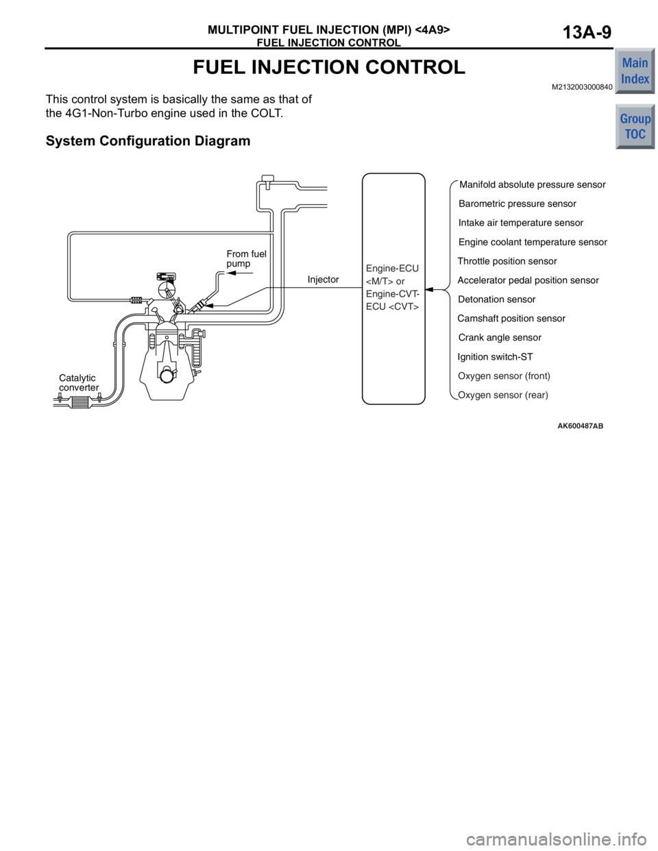
FUEL INJECTION CONTROL
M2132003000840
This control system is basically the same as that of
the 4G1-Non-Turbo engine used in the COLT.
System Configuration Diagram
AK600487
Catalytic
converterInjector
From fuel
pump
AB
Manifold absolute pressure sensor
Engine-ECU
Engine-CVT-
ECU
Intake air temperature sensor
Engine coolant temperature sensor
Throttle position sensor
Accelerator pedal position sensor Detonation sensor
Camshaft position sensor Crank angle sensor
Ignition switch-ST Oxygen sensor (front)
Oxygen sensor (rear)
Page 105 of 364
IGNITION TIMING AND DISTRIBUTION CONTROL
MULTIPOINT FUEL INJECTION (MPI) <4A9>13A-11
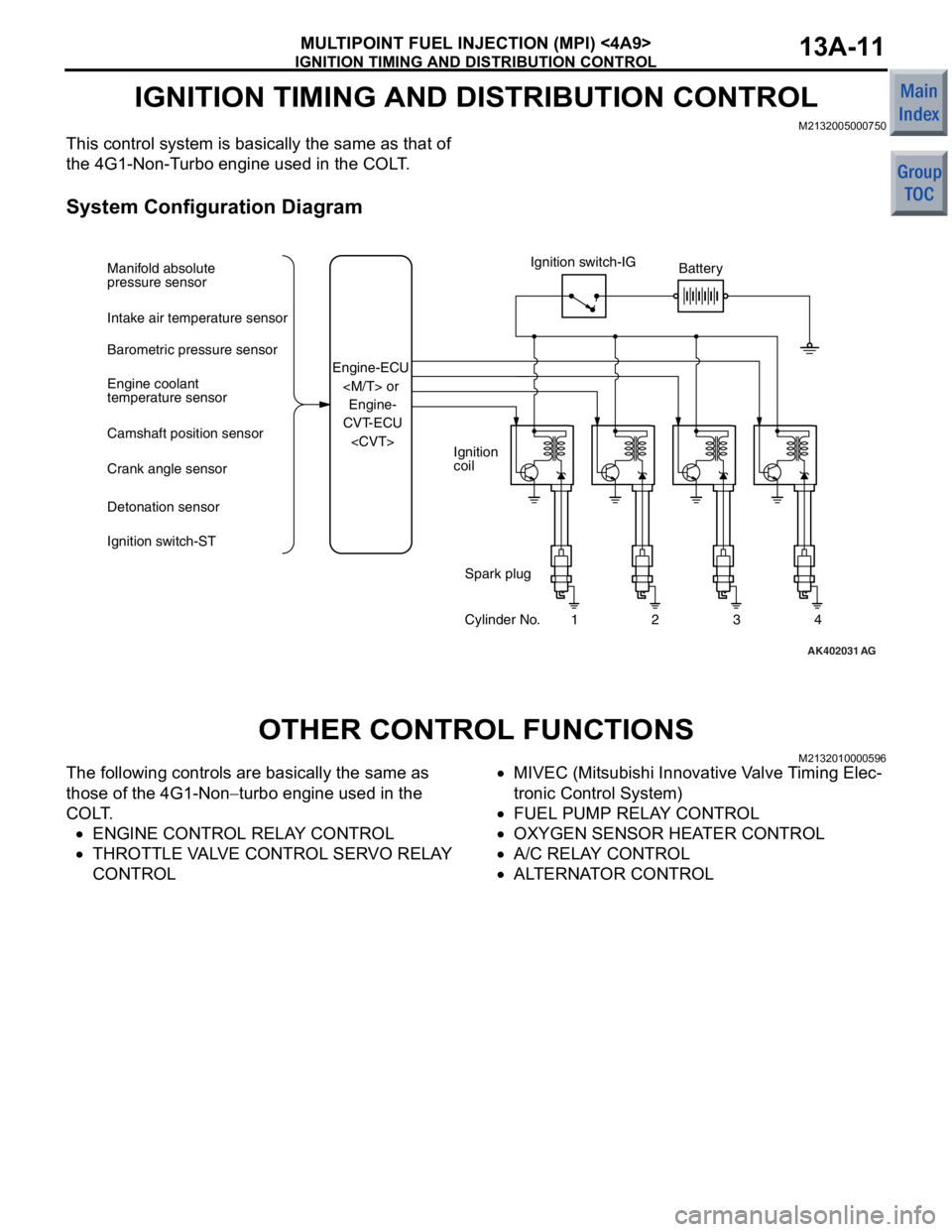
IGNITION TIMING AND DISTRIBUTION CONTROL
M2132005000750
This control system is basically the same as that of
the 4G1-Non-Turbo engine used in the COLT.
System Configuration Diagram
AK402031
Ignition switch-IG
Ignition
coil Battery
Spark plug
Cylinder No. 1 2 3 4
Manifold absolute
pressure sensor
Intake air temperature sensor
Barometric pressure sensor
Engine coolant
temperature sensor
Camshaft position sensor
Crank angle sensor
Detonation sensor
Ignition switch-ST
Engine-ECU
CVT-ECU
AG
OTHER CONTROL FUNCTI O NS
M21320100 0059 6
The following co ntrols are b a sically t he sa me a s
those
of the 4G1 - No n
−turbo eng ine u s ed in the
CO
L
T
.
•ENGINE CONTROL RELA Y CONTROL
•THROTTLE VA L V E C O NTROL SER VO R E LA Y
CONTROL
•MIVEC (Mitsub i sh i Inno vative V a lve T i ming Elec-
tronic Con t rol System)
•FUEL PUMP RELA Y CONTROL
•OXYGEN S E NSOR HEA T E R CONTR O L
•A/C RELAY CONTROL
•ALTER N A T OR CONTROL
Page 114 of 364

DIAGNOSIS SYSTEM
MULTIPOINT FUEL INJECTION (MPI) <4A9>13A-20
ACTUATOR TEST FUNCTION
The actuator test items are given in the table below
Item No.Inspection itemDrive contents
01InjectorsCut fuel to No.1 injector
02Cut fuel to No.2 injector
03Cut fuel to No.3 injector
04Cut fuel to No.4 injector
07Fuel pumpFuel pump operates
08Purge control solenoid valveSolenoid valve turns from OFF to ON
17Basic ignition timingSet to ignition adjustment mode
20Cooling fan control relayDrive the fan motor
34Throttle valve control servoStop the throttle valve control servo
Page 117 of 364
![MITSUBISHI COLT 2006 Service Repair Manual
GENERAL INFORMATION
MULTIPOINT FUEL INJECTION (MPI) <4G1>13B-3
SYSTEM BLOCK DIAGRAM
AK600528
Barometric pressure sensorEngine control unitEngine-ECU
[1] Fuel injection control
[2] Throttle valve open MITSUBISHI COLT 2006 Service Repair Manual
GENERAL INFORMATION
MULTIPOINT FUEL INJECTION (MPI) <4G1>13B-3
SYSTEM BLOCK DIAGRAM
AK600528
Barometric pressure sensorEngine control unitEngine-ECU
[1] Fuel injection control
[2] Throttle valve open](/img/19/57093/w960_57093-116.png)
GENERAL INFORMATION
MULTIPOINT FUEL INJECTION (MPI) <4G1>13B-3
SYSTEM BLOCK DIAGRAM
AK600528
Barometric pressure sensorEngine control unitEngine-ECU
[1] Fuel injection control
[2] Throttle valve opening control
and idle speed control
[3] MIVEC (Mitsubishi Innovative
Valve timing Electronic
control system)
[4] Ignition timing control
[5] Engine control relay control
[6] Throttle valve control servo
relay control
[7] Fuel pump relay control
[8] Oxygen sensor (front) heater
control
[9] Oxygen sensor (rear) heater
control
[10] Fuel pressure control
[11] Waste gate control
[12] Fan relay control
[13] A/C compressor relay
control
[14] Alternator control
[15] Purge control
[16] Diagnostic output
[17] RAM data transmission Throttle valve control unit
Throttle opening feedback control
Engine coolant
temperature sensor Intake air temperature sensor Air flow sensor
Accelerator pedal
position sensor (main) Throttle position sensor (sub)
Camshaft position sensor
Crank angle sensor
Oxygen sensor (front)
Oxygen sensor (rear)
Alternator FR terminal
Clutch switch
Detonation sensor
Ignition switch-IG
Ignition switch-ST
Stop lamp switch
Power supply
Throttle position sensor (main)
Accelerator pedel
position sensor (sub)
Throttle valve control servo No.1 injector
No.2 injector
No.3 injector
No.4 injector
No.1 Ignition coil
No.2 Ignition coil
No.3 Ignition coil
No.4 Ignition coil
Engine control relay
Throttle valve control servo relay
Waste gate solenoid valve
A/C compressor relay
Fuel pump relay
Alternator G terminal
Cooling fan control relay (Hi, Lo)
Purge control solenoid valve
Diagnostic output terminal
Oxygen sensor (front) heater
Oxygen sensor (rear) heater Oil feeder control valve
(for MIVEC)
Fuel pressure control
solenoid valve
AB
Page 118 of 364
GENERAL INFORMATION
MULTIPOINT FUEL INJECTION (MPI) <4G1>13B-4
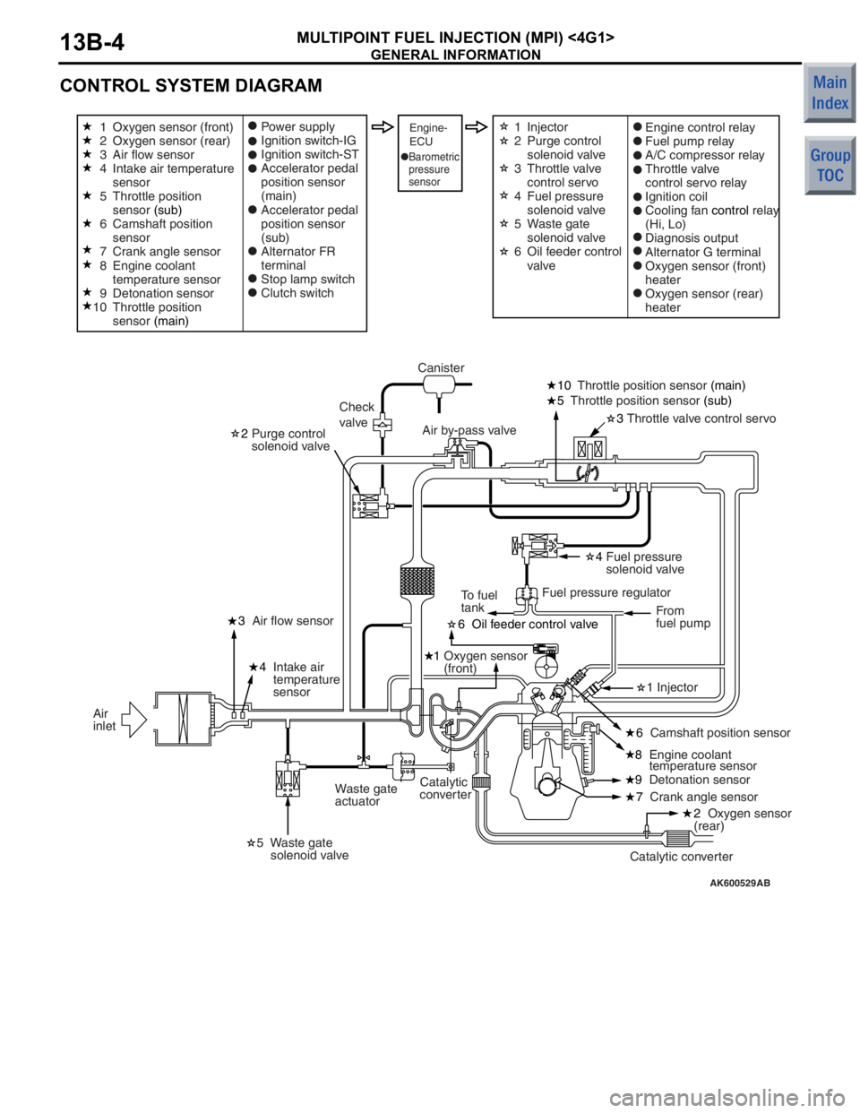
CONTROL SYSTEM DIAGRAM
AK600529AB
6 Oil feeder control valve
1 Oxygen sensor
(front)
8 Engine coolant
temperature sensor
3
Throttle valve control servo
10
Throttle position sensor (main)
5 Throttle position sensor (sub)
2 Purge control
solenoid valve
4 Fuel pressure
solenoid valve
7 Crank angle sensor
9
Detonation sensor
4
Intake air
temperature
sensor
3
Air flow sensor
Waste gate
actuator Canister
Check
valve Air by-pass valve
Fuel pressure regulatorFrom
fuel pump
To fuel
tank
Catalytic converter
Catalytic
converter
Air
inlet
Oxygen sensor (front)
Oxygen sensor (rear)
Air flow sensor
Intake air temperature
sensor
Throttle position
sensor
(sub)
Camshaft position
sensor
Crank angle sensor
Engine coolant
temperature sensor
Detonation sensor
Throttle position
sensor (main) Power supply
Ignition switch-IG
Ignition switch-ST
Accelerator pedal
position sensor
(main)
Accelerator pedal
position sensor
(sub)
Alternator FR
terminal
Stop lamp switch
Clutch switchEngine-
ECUEngine control relay
Fuel pump relay
A/C compressor relay
Throttle valve
control servo relay
Ignition coil
Cooling fan
control relay
(Hi, Lo)
Diagnosis output
Alternator G terminal
Oxygen sensor (front)
heater
Oxygen sensor (rear)
heater
Barometric
pressure
sensor
1 Injector
5 Waste gate
solenoid valve
2 Oxygen sensor
(rear)
6 Camshaft position sensor
1
2
3
4
5
6
7
8
9
10 Injector
Purge control
solenoid valve
Throttle valve
control servo
Fuel pressure
solenoid valve
Waste gate
solenoid valve
Oil feeder control
valve
1
2
3
4
5
6
Page 120 of 364

GENERAL INFORMATION
MULTIPOINT FUEL INJECTION (MPI) <4G1>13B-6
Camshaft position sensorThis sensor detects the top-dead-center (TDC) of the
compression stroke of each cylinder.
Crank angle sensorThis sensor detects the crank angle and inputs it into
the engine-ECU. The engine-ECU effects injector
control and other controls in accordance with the
signals received from this sensor.
Detonation sensorThis sensor, which contains a piezoelectric element,
detects the vibration of the cylinder block that results
from knocking. The engine-ECU detects only the
knocking of the engine from these vibrations, in order
to retard the ignition timing in accordance with the
strength of the knocks.
Alternator FR terminalThis terminal is used for detecting the duty cycle ratio
that energizes the alternator field coil.
Stop lamp switchThis is a contact point type switch that detects how
the brake pedal is depressed.
Actuators
Engine control relayThis relay turns ON and OFF the engine-ECU power
circuit.
Throttle valve control servo relayThis relay turns ON and OFF the actuation power
circuit for the throttle valve control servo in the
engine-ECU.
InjectorThe injectors inject fuel in accordance with the
injection signals received from the engine-ECU.
Ignition coil (with power transistor)Applies ignition coil primary current intermittently in
accordance with the ignition signals received from
the engine-ECU, in order to generate high voltage for
ignition.
Fuel pump relayControls the power supplied to the fuel pump in
accordance with the signals received from the
engine-ECU.
A/C compressor relayControls the operation of the A/C compressor in
accordance with the signals received from the
engine-ECU.
Purge control solenoid valveControls the flow rate of the purge air introduced into
the inlet manifold in accordance with the signals
received from the engine-ECU.
Alternator G terminalControls the amount of current generated by the
alternator in accordance with the signals received
from the engine-ECU.
Cooling fan control relayControls the speed of the cooling fan in accordance
with the signals received from the engine-ECU.
Throttle valve control servoControls the throttle valve position in accordance with
the signals received from the engine-ECU.
ECU
Name Function