relay MITSUBISHI COLT 2006 Service Repair Manual
[x] Cancel search | Manufacturer: MITSUBISHI, Model Year: 2006, Model line: COLT, Model: MITSUBISHI COLT 2006Pages: 364, PDF Size: 11.65 MB
Page 7 of 364
CONSTRUCTION DESCRIPTION
ANTI-SKID BRAKE SYSTEM (ABS)35B-7
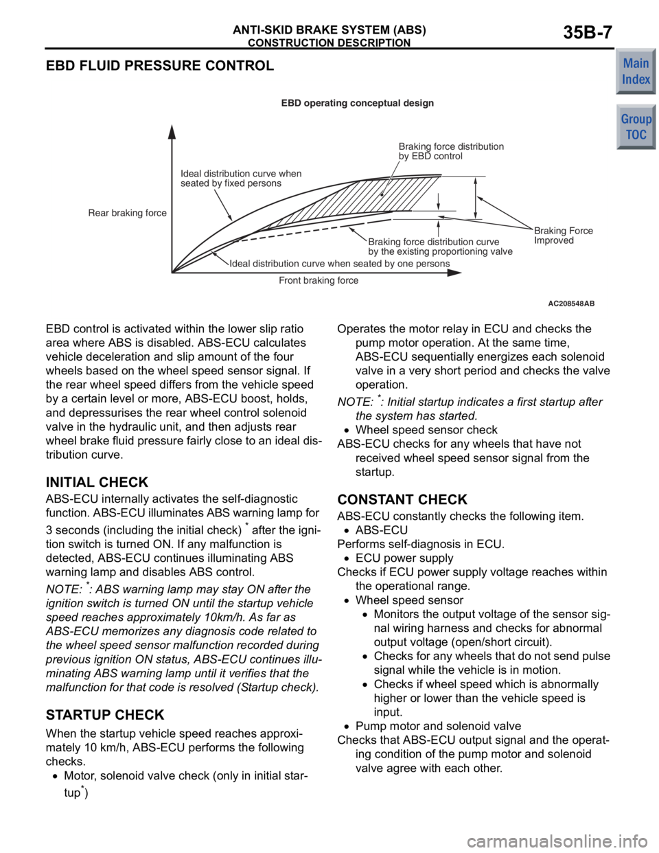
EBD FLUID PRESSURE CONTROL
AC208548AB
Ideal distribution curve when
seated by fixed personsEBD operating conceptual design
Rear braking force
Ideal distribution curve when seated by one persons Braking force distribution curve
by the existing proportioning valveBraking force distribution
by EBD control
Front braking force
Braking Force
Improved
EBD control is
activate d within the lower slip ratio
area where
ABS is disab l ed. ABS-ECU calculates
vehicle
decelera t ion a nd slip amou nt of th e four
whe
e ls based on the wheel sp eed senso r signal. If
the rear
wh eel speed dif f ers f r om th e ve hicle speed
by a
cert ain level or more, ABS-ECU boost, holds,
and de
pressurises the rea r wh eel contro l so leno id
valve in the h
y drau lic unit, and then a d just s rear
whe
e l b r ake fluid pressure fa ir ly close to an ideal dis
-
tribution curve.
INITIAL CHECK
ABS-ECU inter nally activates the self-d iagno stic
function. ABS-ECU illuminates
ABS warning l a mp for
3 seconds (in
c lu ding the in itia l check)
* after th e ign i-
tion switch is turned ON. If a n y malf unction is
detected, ABS-ECU cont
inues illuminating ABS
war
n ing lamp and disables ABS cont rol.
NOTE: *: ABS warning lamp may st ay ON af ter the
ignition
switch is turned ON un til t he st artu p ve hicle
spee
d reaches approximately 10km/h . As far as
ABS-ECU memorizes any d i agn osis code related t o
the
whee l speed sen s or malfunct i on record ed d u ring
previous ignition ON st atus, ABS-ECU continues illu
-
mina ting ABS warn ing lamp until it verif i es that th e
malfunct
i on for tha t co de is resolved (S t a rtup che ck).
STARTUP CHECK
When th e st artup veh i cle sp eed re ache s app roxi-
mately 10 km/h, ABS-ECU performs the following
checks.
•Motor, solen o id valve check (onl y i n ini t ial st ar-
tup*)
Operat es the motor relay in ECU and checks the
pump motor op eratio n. At the same time,
ABS-ECU sequentially e nergizes each solenoid
valve in a ve ry sh ort perio d and ch ecks the valve
ope ration .
NOTE: *: Initia l st artu p ind i ca tes a first st artup af ter
the
system has st arted .
•Whee l speed sensor check
ABS-ECU che cks for a n y whee ls that ha ve no t
received whee l sp eed sens or signal from the
st artu p.
CONSTANT CHECK
ABS-ECU con s t antly ch ecks th e following item.
•ABS-ECU
Performs se lf-diagnosis in ECU.
•ECU power supply
Checks if ECU po we r sup p ly volt ag e reaches within
the operat ional range .
•Whee l speed sensor
•Monitors the ou tput volt age of the sensor sig-
nal wiring ha rness an d che c ks for a bnormal
output
volt ag e (ope n/sho r t circuit).
•Checks fo r any wheels tha t do n o t send pu lse
sig
nal while th e ve hicle is in motion.
•Checks if wheel spee d which is abno rmally
high
er or lo we r than the vehicle speed is
inpu
t.
•Pump mo tor and solenoid valve
Checks tha t ABS-ECU outp u t signal and t he ope rat-
ing co ndition of the pump motor an d so leno id
valve agree
with ea ch ot her .
Page 9 of 364

CONSTRUCTION DESCRIPTION
ANTI-SKID BRAKE SYSTEM (ABS)35B-9
C1226Control solenoid
valve (FR) pressure
holding system ProhibitedProhibitedOutput
permittedONON
C1231Control solenoid
valve (FR)
decompressing
system
C1236Control solenoid
valve (FL) pressure
holding system
C1241Control solenoid
valve (FL) pressure
reducing system
C1246Control solenoid
valve (RR)
pressure holding
system
C1251Control solenoid
valve (RR)
pressure reducing
system
C1256Control solenoid
valve (RL) pressure
holding system
C1261Control solenoid
valve (RL)
decompressing
system
C1266Motor system
(stuck)ProhibitedEnabledOutput
permittedOFFON
C1273Motor relay stuck
off
C1274Motor relay stuck
on
C1276Valve relay systemSystem
shut-downSystem
shut-downOutput
permittedONON
C1278Valve relay system
stuck offSystem
shut-downSystem
shut-downOutput
permittedONON
C1279Valve relay system
stuck onProhibitedEnabledOutput
permittedOFFON
Diagnosis
code No.Item Action during fail-safe operation
ABS control EBD control CAN output Brake
warning
lampABS
warning
lamp
Page 95 of 364
GROUP 13A
MULTIPOINT FUEL INJECTION (MPI)
<4A9>
CONTENTS
GENERAL INFORMATIO N . . . . . . . .13A-2
FUEL INJECTION CONTROL . . . . . .13A-9
THROTTLE VALVE OPENING
ANGLE CONTROL AND IDLE
SPEED CONTROL . . . . . . . . . . . . . . .13A-10
IGNITION TIMING AND
DISTRIBUTION CONTROL . . . . . . . .13A-11
OTHER CONTROL FUNCTIONS . . . .13A-11
FAN RELAY CONTROL . . . . . . . . . . .13A-12
CONTROLLER AREA NETWORK
(CAN) . . . . . . . . . . . . . . . . . . . . . . . . .13A-13
DIAGNOSIS SYSTEM. . . . . . . . . . . . .13A-14
Page 96 of 364

GENERAL INFORMATION
MULTIPOINT FUEL INJECTION (MPI) <4A9>13A-2
GENERAL INFORMATION
M2132000100990
Although the control systems are basically the same
as those of the 4G1-Non-Turbo engine used in the
COLT, the following improvements have been added.
ImprovementRemark
Dual oxygen sensor is used Higher reliability of air-fuel ratio control
Fan relay control is changedAbolish the two stage control of the fan rotating speed.
Page 97 of 364
GENERAL INFORMATION
MULTIPOINT FUEL INJECTION (MPI) <4A9>13A-3
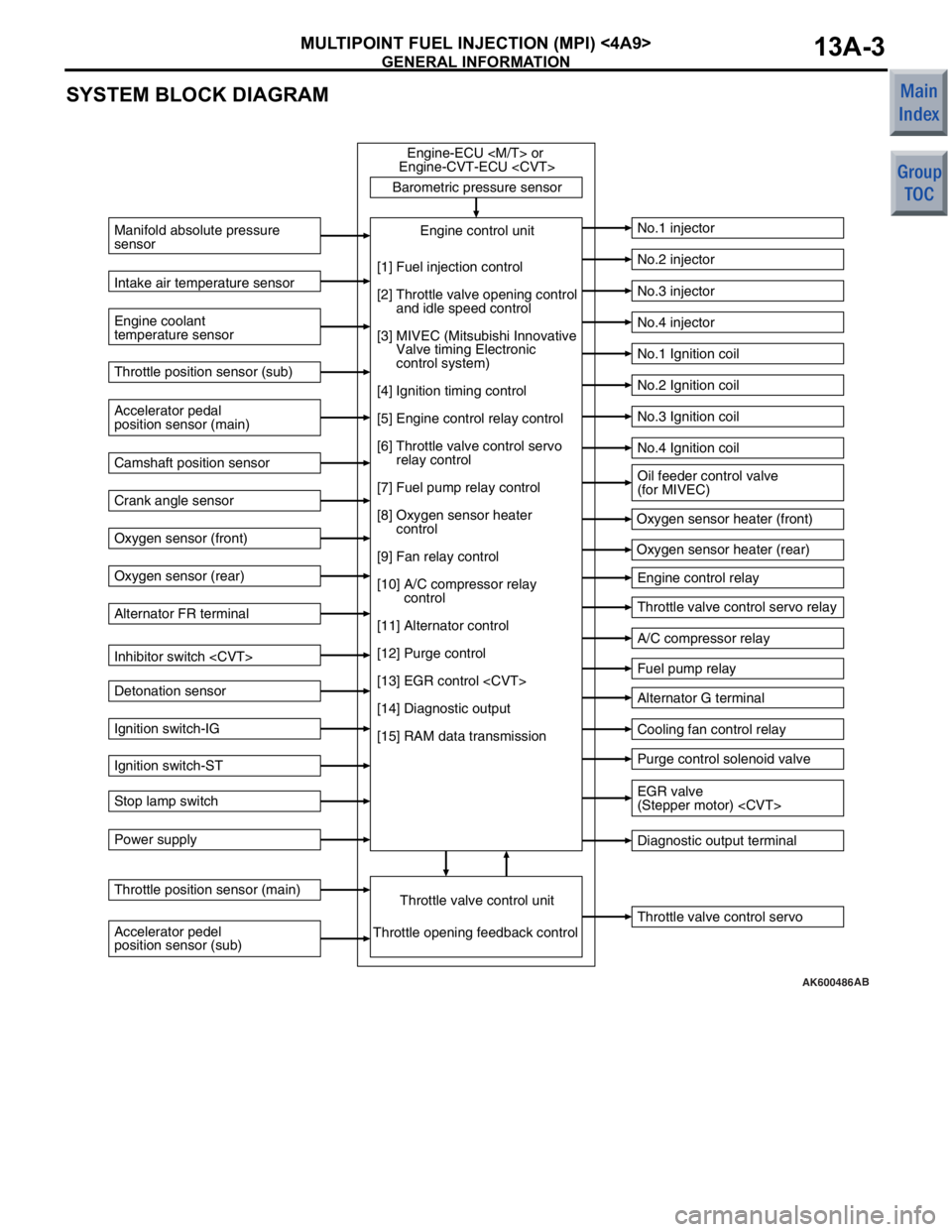
SYSTEM BLOCK DIAGRAM
AK600486
Barometric pressure sensorThrottle valve control servo
Manifold absolute pressure
sensor
Engine coolant
temperature sensor
No.1 injector
No.2 injector
No.3 injector
No.4 injector
No.1 Ignition coil
No.2 Ignition coil
No.3 Ignition coil
No.4 Ignition coil
Engine control relay
Throttle valve control servo relay
A/C compressor relay
Fuel pump relay
Alternator G terminal
Cooling fan control relay
Purge control solenoid valve
Diagnostic output terminal
Intake air temperature sensor
Accelerator pedal
position sensor (main) Throttle position sensor (sub)
Camshaft position sensor
Crank angle sensor
Oxygen sensor (front)
Oxygen sensor (rear)
Alternator FR terminal
Inhibitor switch
Detonation sensor
Ignition switch-IG
Ignition switch-ST
Stop lamp switch
Power supply
Accelerator pedel
position sensor (sub) Throttle position sensor (main)
Throttle valve control unitEngine control unit
Engine-ECU
Engine-CVT-ECU
Throttle opening feedback control Oxygen sensor heater (front)
Oxygen sensor heater (rear)
[1] Fuel injection control
[2] Throttle valve opening control
and idle speed control
[3] MIVEC (Mitsubishi Innovative
Valve timing Electronic
control system)
[4] Ignition timing control
[5] Engine control relay control
[6] Throttle valve control servo
relay control
[7] Fuel pump relay control
[8] Oxygen sensor heater
control
[9] Fan relay control
[10] A/C compressor relay
control
[11] Alternator control
[12] Purge control
[13] EGR control
[14] Diagnostic output
[15] RAM data transmission
Oil feeder control valve
(for MIVEC)
EGR valve
(Stepper motor)
AB
Page 98 of 364
GENERAL INFORMATION
MULTIPOINT FUEL INJECTION (MPI) <4A9>13A-4
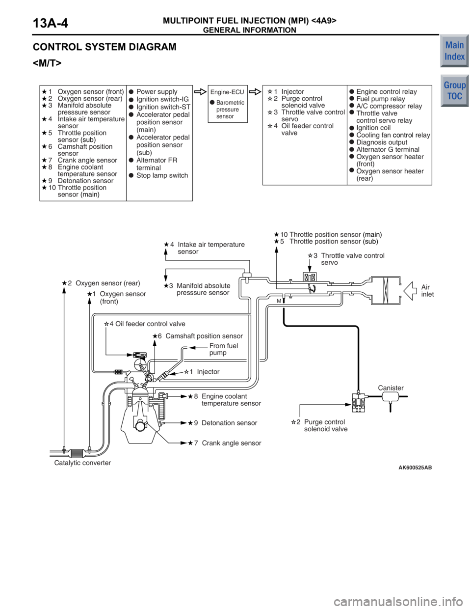
CONTROL SYSTEM DIAGRAM
AK600525
1 Oxygen sensor
(front)4 Intake air temperature
sensor
3 Manifold absolute
presssure sensor
2 Oxygen sensor (rear) 3 Throttle valve control
servo
10 Throttle position sensor
(main)
2 Purge control
solenoid valve
8 Engine coolant
temperature sensor
9 Detonation sensor
7 Crank angle sensor
6 Camshaft position sensor
4 Oil feeder control valve
1 Injector
AB
M
1 Oxygen sensor (front)
2 Oxygen sensor (rear)
3 Manifold absolute
presssure sensor
4 Intake air temperature
sensor
5 Throttle position
sensor
(sub)
6 Camshaft position
sensor
7 Crank angle sensor
8 Engine coolant
temperature sensor
9 Detonation sensor
10 Throttle position
sensor (main) 1 Injector
2 Purge control
solenoid valve
3 Throttle valve control
servo
4 Oil feeder control
valve
Power supply
Ignition switch-IG
Ignition switch-ST
Accelerator pedal
position sensor
(main)
Accelerator pedal
position sensor
(sub)
Alternator FR
terminal
Stop lamp switchEngine-ECUEngine control relay
Fuel pump relay
A/C compressor relay
Throttle valve
control servo relay
Ignition coil
Cooling fan
control relay
Diagnosis output
Alternator G terminal
Oxygen sensor heater
(front)
Oxygen sensor heater
(rear)
Canister Air
inlet
Catalytic converter From fuel
pump
5 Throttle position sensor
(sub)
Barometric
pressure
sensor
Page 99 of 364
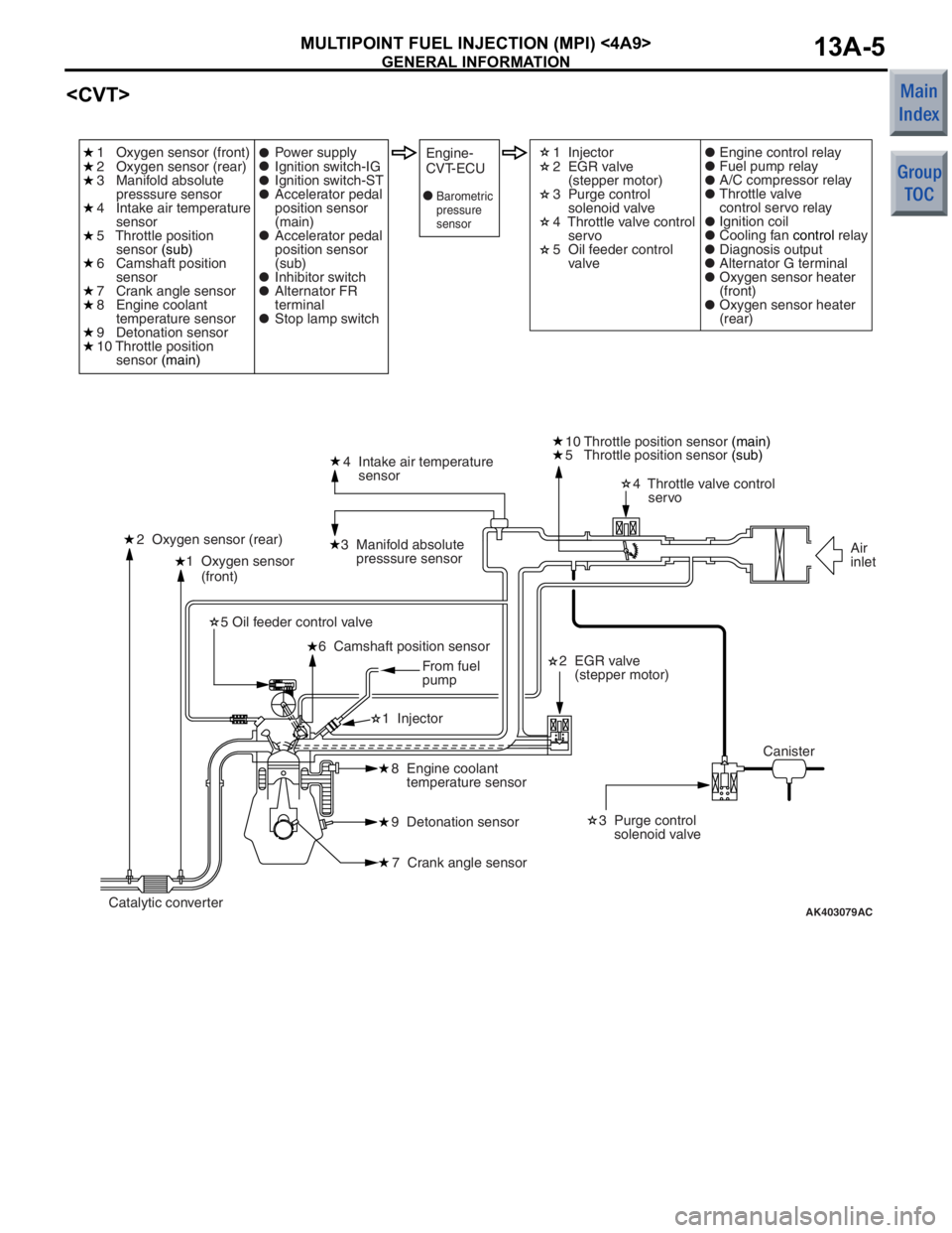
GENERAL INFORMATION
MULTIPOINT FUEL INJECTION (MPI) <4A9>13A-5
AK403079
1 Oxygen sensor
(front)4 Intake air temperature
sensor
3 Manifold absolute
presssure sensor
2 Oxygen sensor (rear) 4 Throttle valve control
servo
10 Throttle position sensor
(main)
2 EGR valve
(stepper motor) 3 Purge control
solenoid valve
8 Engine coolant
temperature sensor
9 Detonation sensor
7 Crank angle sensor
6 Camshaft position sensor
5 Oil feeder control valve
1 Injector
AC
1 Oxygen sensor (front)
2 Oxygen sensor (rear)
3 Manifold absolute
presssure sensor
4 Intake air temperature
sensor
5 Throttle position
sensor (sub)
6 Camshaft position
sensor
7 Crank angle sensor
8 Engine coolant
temperature sensor
9 Detonation sensor
10 Throttle position
sensor (main) 1 Injector
2 EGR valve
(stepper motor)
3 Purge control
solenoid valve
4 Throttle valve control
servo
5 Oil feeder control
valve
Power supply
Ignition switch-IG
Ignition switch-ST
Accelerator pedal
position sensor
(main)
Accelerator pedal
position sensor
(sub)
Inhibitor switch
Alternator FR
terminal
Stop lamp switchEngine-
CVT-ECUEngine control relay
Fuel pump relay
A/C compressor relay
Throttle valve
control servo relay
Ignition coil
Cooling fan
control relay
Diagnosis output
Alternator G terminal
Oxygen sensor heater
(front)
Oxygen sensor heater
(rear)
Canister Air
inlet
Catalytic converter From fuel
pump
5 Throttle position sensor
(sub)
Barometric
pressure
sensor
Page 101 of 364

GENERAL INFORMATION
MULTIPOINT FUEL INJECTION (MPI) <4A9>13A-7
Throttle position sensor
and inputs it into the engine-ECU
engine-CVT-ECU
is output by this sensor, the engine-ECU
engine-CVT-ECU
feedback control.
Accelerator pedal position sensor
and inputs it into the engine-ECU
engine-CVT-ECU
is output by this sensor, which determines the
accelerator position (and the intention of the driver),
the engine-ECU
effects appropriate fuel injection and throttle valve
position controls.
Camshaft position sensorThis sensor detects the top-dead-center (TDC) of the
compression stroke of each cylinder.
Crank angle sensorThis sensor detects the crank angle and inputs it into
the engine-ECU
The engine-ECU
effects injector control and other controls in
accordance with the signals received from this
sensor.
Detonation sensorThis sensor, which contains a piezoelectric element,
detects the vibration of the cylinder block that results
from knocking. The engine-ECU
engine-CVT-ECU
of the engine from these vibrations, in order to retard
the ignition timing in accordance with the strength of
the knocks.
Alternator FR terminalThis terminal is used for detecting the duty cycle ratio
that energizes the alternator field coil.
Inhibitor switch
into the engine-CVT-ECU to determine whether the
shift lever is in the neutral position.
Stop lamp switchThis is a contact point type switch that detects how
the brake pedal is depressed.
Actuators
Engine control relayThis relay turns ON and OFF the engine-ECU
or engine-CVT-ECU
Throttle valve control servo relayThis relay turns ON and OFF the actuation power
circuit for the throttle valve control servo in the
engine-ECU
InjectorThe injectors inject fuel in accordance with the
injection signals received from the engine-ECU
Ignition coil (with power transistor)Applies ignition coil primary current intermittently in
accordance with the ignition signals received from
the engine-ECU
in order to generate high voltage for ignition.
Name Function
Page 102 of 364

GENERAL INFORMATION
MULTIPOINT FUEL INJECTION (MPI) <4A9>13A-8
Fuel pump relayControls the power supplied to the fuel pump in
accordance with the signals received from the
engine-ECU
A/C compressor relayControls the operation of the A/C compressor in
accordance with the signals received from the
engine-ECU
Purge control solenoid valveControls the flow rate of the purge air introduced into
the inlet manifold in accordance with the signals
received from the engine-ECU
engine-CVT-ECU
EGR valve (stepper motor)
signals received from the engine-CVT-ECU.
Alternator G terminalControls the amount of current generated by the
alternator in accordance with the signals received
from the engine-ECU
Cooling fan control relayControls the rotation of cooling the fan in accordance
with the signals received from the engine-ECU
Throttle valve control servoControls the throttle valve position in accordance with
the signals received from the engine-ECU
engine-CVT-ECU
Oil feeder control valveThe oil feeder control valve, which is actuated by the
signals received from the engine-ECU
engine-CVT-ECU
Oxygen sensor heater
in accordance with the signals received from the
engine-ECU
Name Function
Page 104 of 364
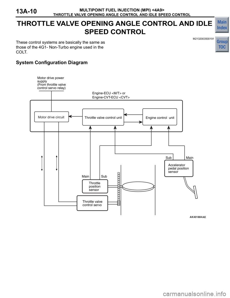
THROTTLE VALVE OPENING ANGLE CONTROL AND IDLE SPEED CONTROL
MULTIPOINT FUEL INJECTION (MPI) <4A9>13A-10
THROTTLE VALVE OPENING ANGLE CONTROL AND IDLE
SPEED CONTROL
M2132003500191
These control systems are basically the same as
those of the 4G1- Non-Turbo engine used in the
COLT.
System Configuration Diagram
AK401884AE
Motor drive power
supply
(From throttle valve
control servo relay)
Engine-ECU
Engine-CVT-ECU
Throttle
position
sensor
Main Sub Sub Main
Throttle valve
control servo Accelerator
pedal position
sensor
Throttle valve control unit
Engine control unit
Motor drive circuit