lamp MITSUBISHI COLT 2009 10.G Owner's Manual
[x] Cancel search | Manufacturer: MITSUBISHI, Model Year: 2009, Model line: COLT, Model: MITSUBISHI COLT 2009 10.GPages: 273, PDF Size: 17.28 MB
Page 34 of 273
Downloaded from www.Manualslib.com manuals search engine Central door locksE00300801445
NOTE l Each of the doors can be locked or unlocked
independently by using the inside lock knob.
l Repeated continuous operation between lock
and unlock could activate the central door
locking systems built-in protection circuit
and prevent the system from operating.
If this occurs, wait about 1 minute before op-
erating the inside lock knob or the key.
All of the doors and the tailgate can be locked and
unlocked as described hereafter.
Front doors with key (LHD vehicles on-
ly)
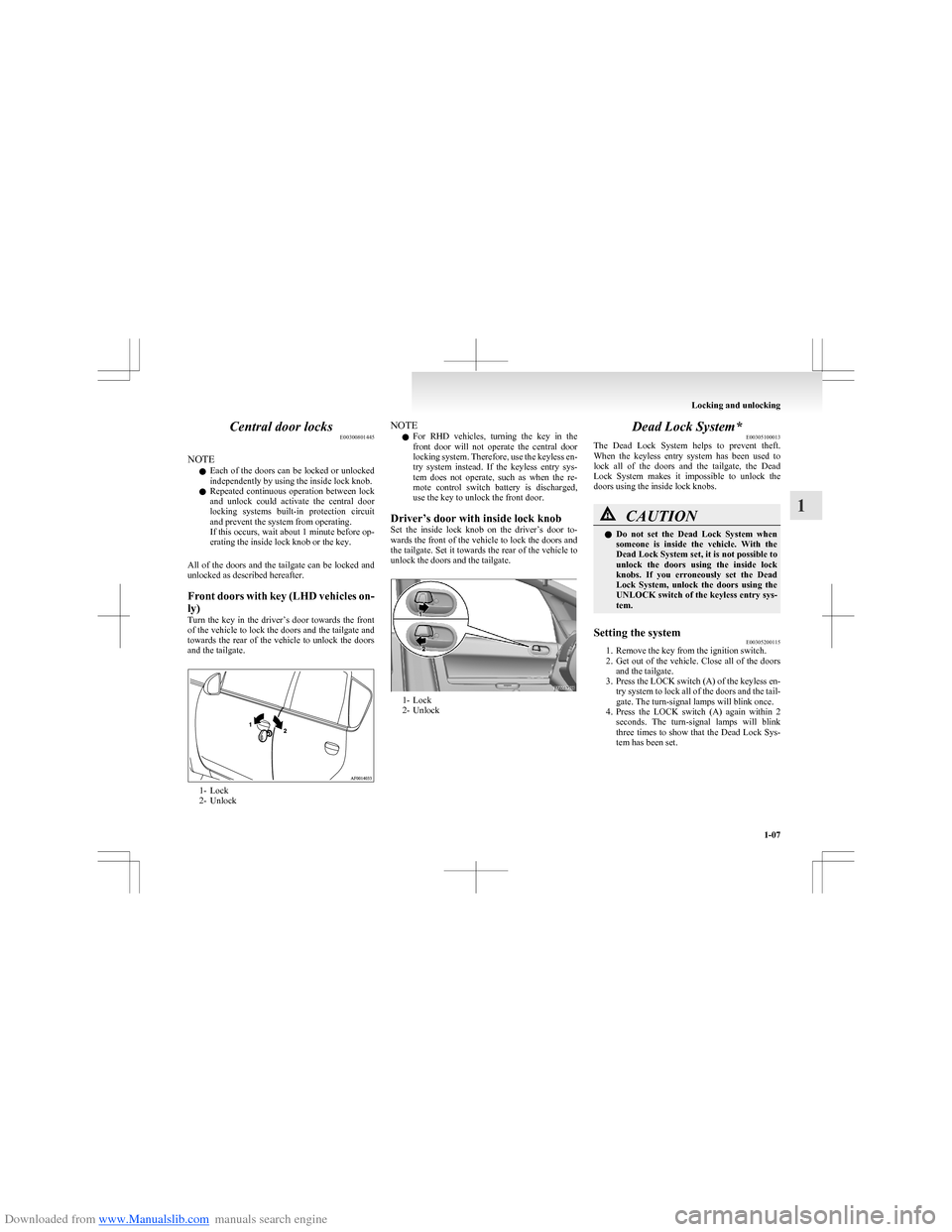
Turn the key in the driver’s door towards the front
of the vehicle to lock the doors and the tailgate and
towards the rear of the vehicle to unlock the doors
and the tailgate.
1- Lock
2- Unlock
NOTE
l For RHD vehicles, turning the key in the
front door will not operate the central door
locking system. Therefore, use the keyless en-
try system instead. If the keyless entry sys-
tem does not operate, such as when the re-
mote control switch battery is discharged,
use the key to unlock the front door.
Driver’s door with inside lock knob
Set the inside lock knob on the driver’s door to-
wards the front of the vehicle to lock the doors and
the tailgate. Set it towards the rear of the vehicle to
unlock the doors and the tailgate.
1- Lock
2- Unlock
Dead Lock System* E00305100013
The Dead Lock System helps to prevent theft.
When the keyless entry system has been used to
lock all of the doors and the tailgate, the Dead
Lock System makes it impossible to unlock the
doors using the inside lock knobs.CAUTIONl Do not set the Dead Lock System when
someone is inside the vehicle. With the
Dead Lock System set, it is not possible to
unlock the doors using the inside lock
knobs. If you erroneously set the Dead
Lock System, unlock the doors using the
UNLOCK switch of the keyless entry sys-
tem.Setting the system E00305200115
1. Remove the key from the ignition switch.
2. Get out of the vehicle. Close all of the doors
and the tailgate.
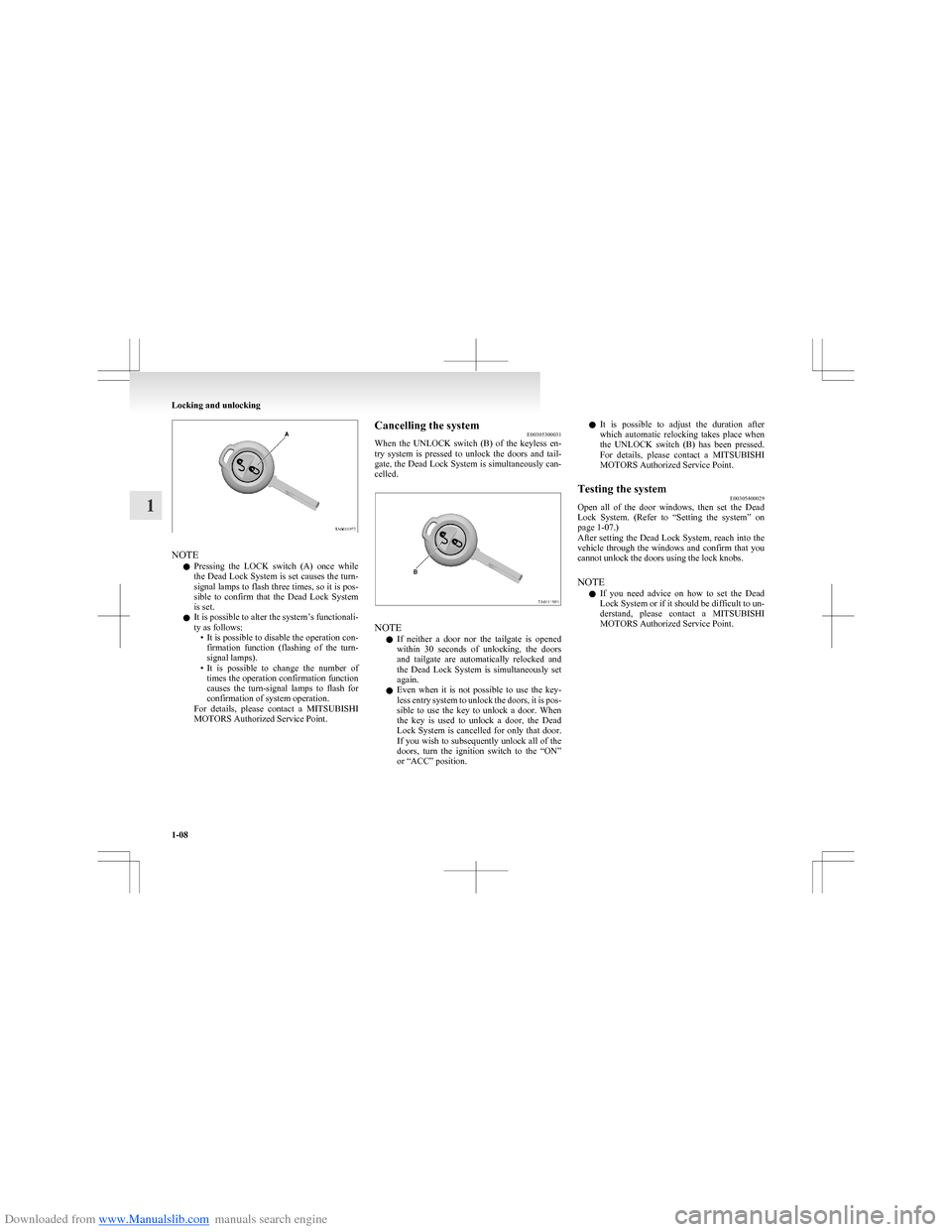
3. Press the LOCK switch (A) of the keyless en-
try system to lock all of the doors and the tail-
gate. The turn-signal lamps will blink once.
4. Press the LOCK switch (A) again within 2
seconds. The turn-signal lamps will blink
three times to show that the Dead Lock Sys-
tem has been set.
Locking and unlocking
1-07
1
Page 35 of 273
Downloaded from www.Manualslib.com manuals search engine NOTEl Pressing the LOCK switch (A) once while
the Dead Lock System is set causes the turn-
signal lamps to flash three times, so it is pos-
sible to confirm that the Dead Lock System
is set.
l It is possible to alter the system’s functionali-
ty as follows: •It is possible to disable the operation con-
firmation function (flashing of the turn-
signal lamps).
• It is possible to change the number of
times the operation confirmation function
causes the turn-signal lamps to flash for
confirmation of system operation.
For details, please contact a MITSUBISHI
MOTORS Authorized Service Point.
Cancelling the system E00305300031
When the UNLOCK switch (B) of the keyless en-
try system is pressed to unlock the doors and tail-
gate, the Dead Lock System is simultaneously can-
celled.
NOTE
l If neither a door nor the tailgate is opened
within 30 seconds of unlocking, the doors
and tailgate are automatically relocked and
the Dead Lock System is simultaneously set
again.
l Even when it is not possible to use the key-
less entry system to unlock the doors, it is pos-
sible to use the key to unlock a door. When
the key is used to unlock a door, the Dead
Lock System is cancelled for only that door.
If you wish to subsequently unlock all of the
doors, turn the ignition switch to the “ON”
or “ACC” position.
l It is possible to adjust the duration after
which automatic relocking takes place when
the UNLOCK switch (B) has been pressed.
For details, please contact a MITSUBISHI
MOTORS Authorized Service Point.Testing the system E00305400029
Open all of the door windows, then set the Dead
Lock System. (Refer to “Setting the system” on
page 1-07.)
After setting the Dead Lock System, reach into the
vehicle through the windows and confirm that you
cannot unlock the doors using the lock knobs.
NOTE l If you need advice on how to set the Dead
Lock System or if it should be difficult to un-
derstand, please contact a MITSUBISHI
MOTORS Authorized Service Point.
Locking and unlocking
1-08
1
Page 45 of 273
Downloaded from www.Manualslib.com manuals search engine Heated seats*E00401100625
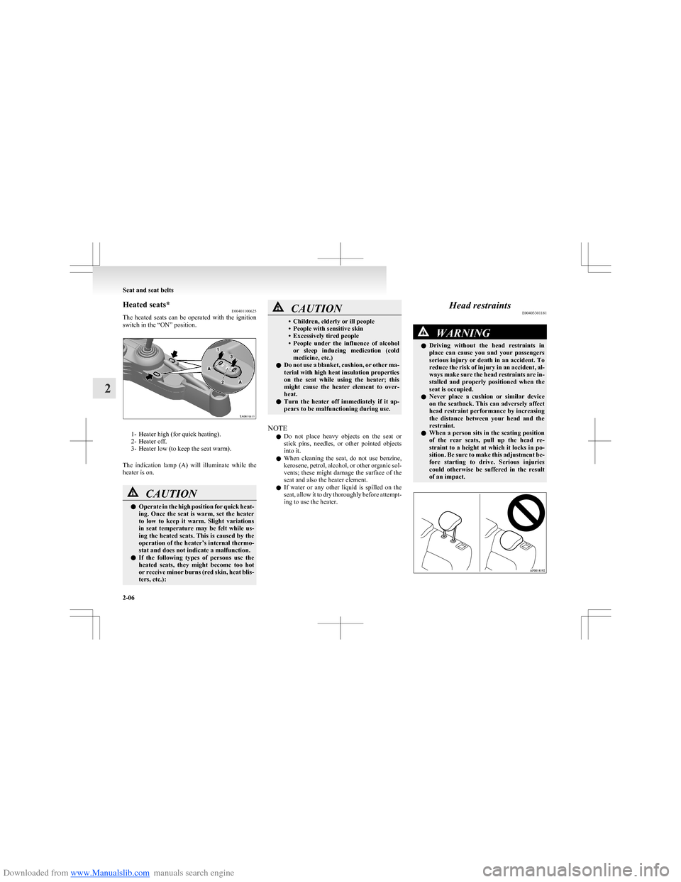
The heated seats can be operated with the ignition
switch in the “ON” position.
1- Heater high (for quick heating).
2- Heater off.
3- Heater low (to keep the seat warm).
The indication lamp (A) will illuminate while the
heater is on.
CAUTIONl Operate in the high position for quick heat-
ing. Once the seat is warm, set the heater
to low to keep it warm. Slight variations
in seat temperature may be felt while us-
ing the heated seats. This is caused by the
operation of the heater’s internal thermo-
stat and does not indicate a malfunction.
l If the following types of persons use the
heated seats, they might become too hot
or receive minor burns (red skin, heat blis-
ters, etc.):CAUTION• Children, elderly or ill people
• People with sensitive skin
• Excessively tired people
• People under the influence of alcohol
or sleep inducing medication (cold
medicine, etc.)
l Do not use a blanket, cushion, or other ma-
terial with high heat insulation properties
on the seat while using the heater; this
might cause the heater element to over-
heat.
l Turn the heater off immediately if it ap-
pears to be malfunctioning during use.
NOTE
l Do not place heavy objects on the seat or
stick pins, needles, or other pointed objects
into it.
l When cleaning the seat, do not use benzine,
kerosene, petrol, alcohol, or other organic sol-
vents; these might damage the surface of the
seat and also the heater element.
l If water or any other liquid is spilled on the
seat, allow it to dry thoroughly before attempt-
ing to use the heater.
Head restraints E00403301181WARNINGlDriving without the head restraints in
place can cause you and your passengers
serious injury or death in an accident. To
reduce the risk of injury in an accident, al-
ways make sure the head restraints are in-
stalled and properly positioned when the
seat is occupied.
l Never place a cushion or similar device
on the seatback. This can adversely affect
head restraint performance by increasing
the distance between your head and the
restraint.
l When a person sits in the seating position
of the rear seats, pull up the head re-
straint to a height at which it locks in po-
sition. Be sure to make this adjustment be-
fore starting to drive. Serious injuries
could otherwise be suffered in the result
of an impact.
Seat and seat belts
2-06
2
Page 50 of 273
Downloaded from www.Manualslib.com manuals search engine CAUTIONlThe seat belts must not be twisted when
worn.
3. Pull the belt slightly to adjust slackness as de-
sired.
To unfasten
Hold the latch plate and push the button on the buck-
le.
NOTE
l As the belt retracts automatically, keep hold-
ing the latch plate while retracting so that the
belt stows slowly. Failure to do this could
damage the vehicle.
Seat belt reminder/warning lamp E00409800497
A tone and warning lamp are used to remind the
driver and front passenger to fasten the seat belt.
NOTE
l For the front passenger seat, the warning func-
tion works only while a person is sitting on
the seat.
When the ignition key is turned to the “ON” posi-
tion, the warning lamp will come on and a tone
will sound for about 6 seconds. If the front seat belt
remains unfastened approximately 1 minute later,
the warning lamp will flash and the tone sound in-
termittently (each 12 times) when the vehicle is driv-
en. If the passenger subsequently unfastens the seat
belt while driving, the warning lamp and tone will
issue further warnings. And if the seat belt remains
unfastened, the warning lamp and tone will issue
further warnings each time the vehicle starts mov-
ing from a stop. When the seat belt is fastened, the
warnings will stop.
WARNINGl In order to reduce the risk of serious or fa-
tal injury in an accident, always wear
your own seat belt. Do not allow anyone
to ride in your vehicle unless he or she is
also seated and wearing a seat belt. Chil-
dren should additionally be restrained in
a secure child restraint system.
NOTE
l When luggage is placed on the front passen-
ger seat, a sensor in the seat cushion may, de-
pending on the weight and position of the lug-
gage, cause the warning tone to sound and
the warning lamp to come on.
Adjustable seat belt anchor (front
seats) E00405000055
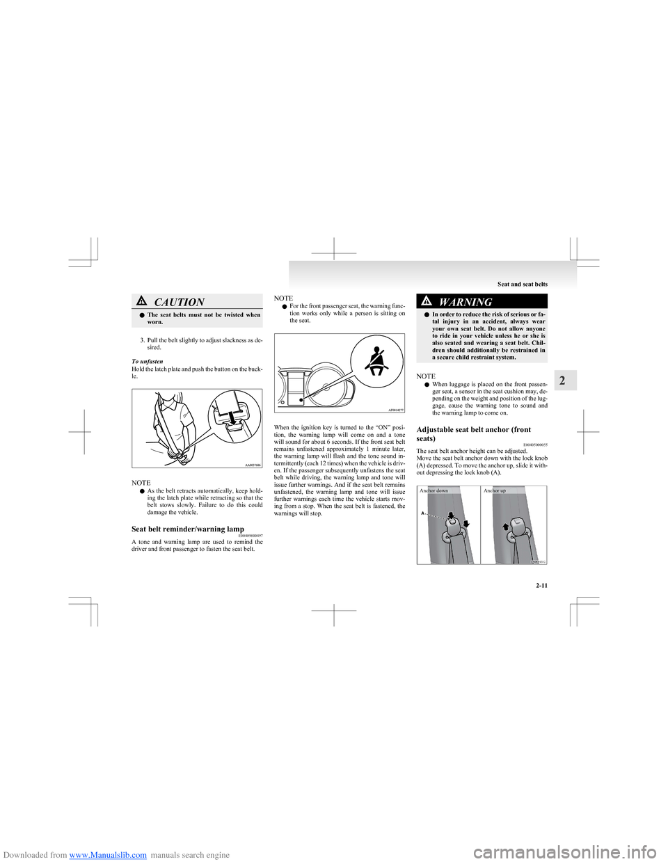
The seat belt anchor height can be adjusted.
Move the seat belt anchor down with the lock knob
(A) depressed. To move the anchor up, slide it with-
out depressing the lock knob (A).
Anchor downAnchor up
Seat and seat belts
2-11
2
Page 52 of 273
Downloaded from www.Manualslib.com manuals search engine Seat belt pretensioner system andforce limiter system E00405700010
The driver’s seat and front passenger’s seat each
have a seat belt equipped with a pretensioner system.Pretensioner system E00405801151
The pretensioner system will retract their respec-
tive seat belts instantaneously, thus maximizing the
seat belt’s effectiveness, if there is a frontal impact
severe enough to injure the driver and/or front pas-
senger and the ignition switch is in the “ON” or
“START” position.
WARNINGl To obtain the best results from your pre-
tensioner seat belt, make sure you do the
following: • Adjust the seat to the proper position.Refer to “Front seat” on page 2-04.
• Fasten your seat belt properly. Refer to “Seat belts” on page 2-10.CAUTIONl Installation of audio equipment or re-
pairs in the vicinity of the pretensioner
seat belts or floor console must be per-
formed in line with MITSUBISHI
MOTORS guidelines. It is important to
do so because the work could affect the
pretensioner systems.CAUTIONl If you need to scrap the vehicle, please con-
sult a MITSUBISHI MOTORS Author-
ized Service Point. It is important to do
so because unexpected activation of the
pretensioner seat belts could cause inju-
ries.
NOTE
l The pretensioner seat belts will be activated
if the vehicle suffers a severe frontal impact,
even if the seat belts are not worn.
l The pretensioner seat belts are designed to
work only once. After the pretensioner seat
belts have been activated, we recommend
you have them replaced by a MITSUBISHI
MOTORS Authorized Service Point.
SRS warning lamp E00405900038
This warning lamp is shared by the SRS airbags
and the pretensioner seat belts. Refer to “SRS warn-
ing lamp” on page 2-33.
Force limiter system E00406000049
In the event of a collision, each force limiter sys-
tem will effectively absorb the load applied to the
seat belt so as to minimize the impact to the passen-
ger.
Child restraint E00406401473
When transporting children in your vehicle, some
type of child restraint system should always be
used according to the size of the child. This is re-
quired by law in most countries.
The regulations concerning driving with children in
the front seat may differ from country to country.
You are advised to comply with the relevant regula-
tions.WARNINGl When possible, put children in the rear
seat. Accident statistics indicate that chil-
dren of all sizes and ages are safer when
properly restrained in the rear seat rath-
er than in the front seat.
l Holding a child in your arms is no substi-
tute for a restraint system. Failure to use
a proper restraint system can result in se-
vere or fatal injury to your child.
l Each child restraint device or fixing is to
be used only by one child.
l When attaching a child restraint to the
rear seat, place the front seatbacks in the
upright position.
Otherwise, the child could be seriously in-
jured in the event of hard braking or a col-
lision.
Seat and seat belts
2-13
2
Page 64 of 273
Downloaded from www.Manualslib.com manuals search engine How the Supplemental Restraint Sys-
tem works E00407301583
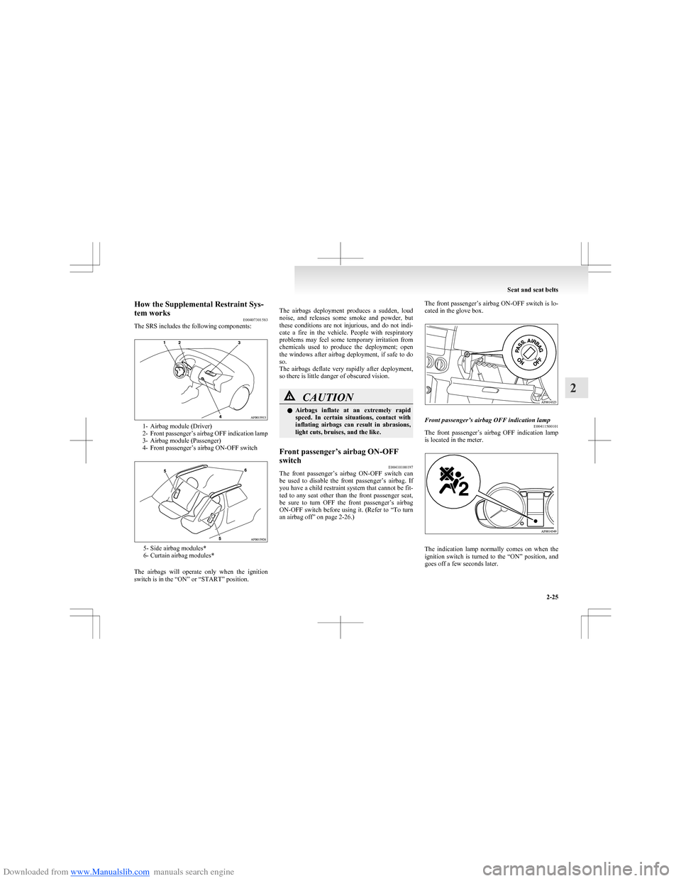
The SRS includes the following components:
1- Airbag module (Driver)
2- Front passenger’s airbag OFF indication lamp
3- Airbag module (Passenger)
4- Front passenger’s airbag ON-OFF switch
5- Side airbag modules*
6- Curtain airbag modules*
The airbags will operate only when the ignition
switch is in the “ON” or “START” position.
The airbags deployment produces a sudden, loud
noise, and releases some smoke and powder, but
these conditions are not injurious, and do not indi-
cate a fire in the vehicle. People with respiratory
problems may feel some temporary irritation from
chemicals used to produce the deployment; open
the windows after airbag deployment, if safe to do
so.
The airbags deflate very rapidly after deployment,
so there is little danger of obscured vision.CAUTIONl Airbags inflate at an extremely rapid
speed. In certain situations, contact with
inflating airbags can result in abrasions,
light cuts, bruises, and the like.Front passenger’s airbag ON-OFF
switch E00410100197
The front passenger’s airbag ON-OFF switch can
be used to disable the front passenger’s airbag. If
you have a child restraint system that cannot be fit-
ted to any seat other than the front passenger seat,
be sure to turn OFF the front passenger’s airbag
ON-OFF switch before using it. (Refer to “To turn
an airbag off” on page 2-26.)
The front passenger’s airbag ON-OFF switch is lo-
cated in the glove box.Front passenger’s airbag OFF indication lamp E00411500101
The front passenger’s airbag OFF indication lamp
is located in the meter.
The indication lamp normally comes on when the
ignition switch is turned to the “ON” position, and
goes off a few seconds later.
Seat and seat belts
2-25
2
Page 65 of 273
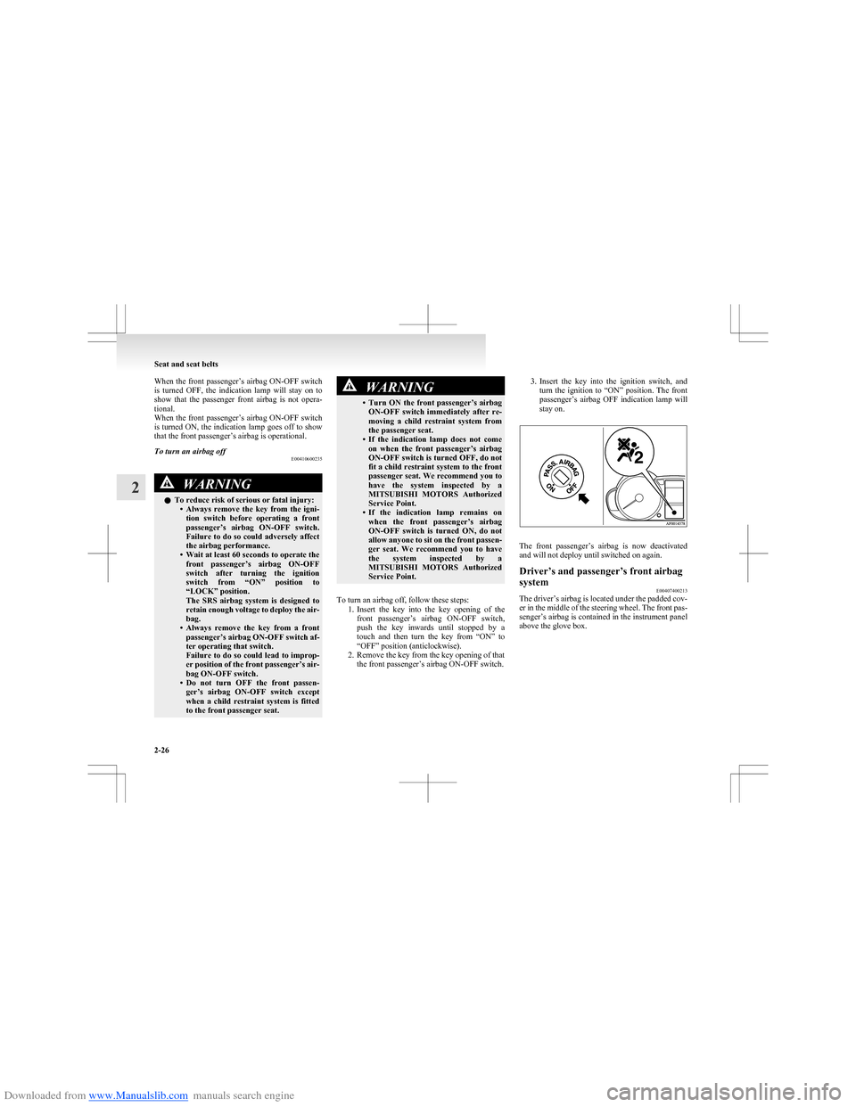
Downloaded from www.Manualslib.com manuals search engine When the front passenger’s airbag ON-OFF switch
is turned OFF, the indication lamp will stay on to
show that the passenger front airbag is not opera-
tional.
When the front passenger’s airbag ON-OFF switch
is turned ON, the indication lamp goes off to show
that the front passenger’s airbag is operational.To turn an airbag off E00410600235WARNINGlTo reduce risk of serious or fatal injury:
•Always remove the key from the igni-
tion switch before operating a front
passenger’s airbag ON-OFF switch.
Failure to do so could adversely affect
the airbag performance.
• Wait at least 60 seconds to operate the
front passenger’s airbag ON-OFF
switch after turning the ignition
switch from “ON” position to
“LOCK” position.
The SRS airbag system is designed to
retain enough voltage to deploy the air-
bag.
• Always remove the key from a front
passenger’s airbag ON-OFF switch af-
ter operating that switch.
Failure to do so could lead to improp-
er position of the front passenger’s air-
bag ON-OFF switch.
• Do not turn OFF the front passen-
ger’s airbag ON-OFF switch except
when a child restraint system is fitted
to the front passenger seat.WARNING• Turn ON the front passenger’s airbag
ON-OFF switch immediately after re-
moving a child restraint system from
the passenger seat.
• If the indication lamp does not come
on when the front passenger’s airbag
ON-OFF switch is turned OFF, do not
fit a child restraint system to the front
passenger seat. We recommend you to
have the system inspected by a
MITSUBISHI MOTORS Authorized
Service Point.
• If the indication lamp remains on
when the front passenger’s airbag
ON-OFF switch is turned ON, do not
allow anyone to sit on the front passen-
ger seat. We recommend you to have
the system inspected by a
MITSUBISHI MOTORS Authorized
Service Point.
To turn an airbag off, follow these steps: 1.Insert the key into the key opening of the
front passenger’s airbag ON-OFF switch,
push the key inwards until stopped by a
touch and then turn the key from “ON” to
“OFF” position (anticlockwise).
2. Remove the key from the key opening of that the front passenger’s airbag ON-OFF switch.
3.Insert the key into the ignition switch, and
turn the ignition to “ON” position. The front
passenger’s airbag OFF indication lamp will
stay on.
The front passenger’s airbag is now deactivated
and will not deploy until switched on again.
Driver’s and passenger’s front airbag
system E00407400213
The driver’s airbag is located under the padded cov-
er in the middle of the steering wheel. The front pas-
senger’s airbag is contained in the instrument panel
above the glove box.
Seat and seat belts
2-26
2
Page 72 of 273
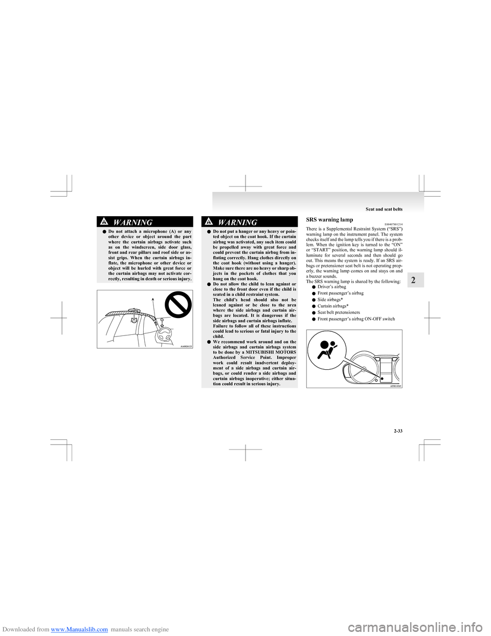
Downloaded from www.Manualslib.com manuals search engine WARNINGlDo not attach a microphone (A) or any
other device or object around the part
where the curtain airbags activate such
as on the windscreen, side door glass,
front and rear pillars and roof side or as-
sist grips. When the curtain airbags in-
flate, the microphone or other device or
object will be hurled with great force or
the curtain airbags may not activate cor-
rectly, resulting in death or serious injury.WARNINGl Do not put a hanger or any heavy or poin-
ted object on the coat hook. If the curtain
airbag was activated, any such item could
be propelled away with great force and
could prevent the curtain airbag from in-
flating correctly. Hang clothes directly on
the coat hook (without using a hanger).
Make sure there are no heavy or sharp ob-
jects in the pockets of clothes that you
hang on the coat hook.
l Do not allow the child to lean against or
close to the front door even if the child is
seated in a child restraint system.
The child’s head should also not be
leaned against or be close to the area
where the side airbags and curtain air-
bags are located. It is dangerous if the
side airbags and curtain airbags inflate.
Failure to follow all of these instructions
could lead to serious or fatal injury to the
child.
l We recommend work around and on the
side airbags and curtain airbags system
to be done by a MITSUBISHI MOTORS
Authorized Service Point. Improper
work could result inadvertent deploy-
ment of a side airbags and curtain air-
bags, or could render a side airbags and
curtain airbags inoperative; either situa-
tion could result in serious injury.SRS warning lamp E00407801214
There is a Supplemental Restraint System (“SRS”)
warning lamp on the instrument panel. The system
checks itself and the lamp tells you if there is a prob-
lem. When the ignition key is turned to the “ON”
or “START” position, the warning lamp should il-
luminate for several seconds and then should go
out. This means the system is ready. If an SRS air-
bags or pretensioner seat belt is not operating prop-
erly, the warning lamp comes on and stays on and
a buzzer sounds.
The SRS warning lamp is shared by the following:
l Driver’s airbag
l Front passenger’s airbag
l Side airbags*
l Curtain airbags*
l Seat belt pretensioners
l Front passenger’s airbag ON-OFF switch
Seat and seat belts
2-33
2
Page 73 of 273
Downloaded from www.Manualslib.com manuals search engine WARNINGlIf any of the following conditions occurs,
the SRS and/or seat belt pretensioners
are not working properly, and we recom-
mend you to have it inspected by a
MITSUBISHI MOTORS Authorized
Service Point immediately. •The SRS warning lamp does not illu-
minate when you start the vehicle.
• The SRS warning lamp does not go
out after several seconds.
• The SRS warning lamp illuminates
while driving.SRS servicing E00407900784WARNINGlWe recommend any maintenance per-
formed on or near the components of the
SRS to be performed by a MITSUBISHI
MOTORS Authorized Service Point.
Improper work on the SRS components
or wiring could result in inadvertent de-
ployment of the airbags, or could render
the SRS inoperative; either situation
could result in serious injury.
l Do not modify your steering wheel, seat
belt retractor or any other SRS compo-
nents. For example, replacement of the
steering wheel, or modifications to the
front bumper or body structure can ad-
versely affect SRS performance and lead
to possible injury.WARNINGl If your vehicle has received any damage,
we recommend you to have the SRS in-
spected to ensure it is in proper working
order.
l On vehicles with the side airbags, do not
modify your front seats, centre pillar and
centre console.
It can adversely affect SRS performance
and lead to possible injury.
Also, if you have found any tear or open
seam in the seat fabric at the portion near
the side airbag, we recommend you to
have the seat inspected.
l On vehicles with the curtain airbags, if
you have found any scratch, crack or dam-
age to the portion of the front and rear pil-
lars and roof side rail, we recommend
you to have the SRS inspected by a
MITSUBISHI MOTORS Authorized
Service Point.
NOTE
l When you transfer ownership of the vehicle
to some other person, we urge you to alert
the new owner that it is equipped with the
SRS and refer that owner to the applicable
section in this owner’s manual.
l If you junk or scrap the vehicle, we urge you
to first take the vehicle to a MITSUBISHI
MOTORS Authorized Service Point so that
the SRS can be rendered safe.
Seat and seat belts
2-34
2
Page 74 of 273
Downloaded from www.Manualslib.com manuals search engine Instruments................................................................................... 3-02
Multi-information display.............................................................3-04
Indication and warning lamps.......................................................3-16
Indication lamps ........................................................................... 3-17
Warning lamps .............................................................................. 3-17
Combination headlamps and dipper switch ..................................3-20
Headlamp levelling switch ........................................................... 3-22
Turn-signal lever...........................................................................3-23
Hazard warning flasher switch ..................................................... 3-23
Front fog lamp switch* ................................................................. 3-24
Rear fog lamp switch .................................................................... 3-24
Wiper and washer switch .............................................................. 3-25
Rear window demister switch.......................................................3-29
Horn switch...................................................................................3-30Instruments and controls3