tow MITSUBISHI COLT 2011 (in English) Owner's Guide
[x] Cancel search | Manufacturer: MITSUBISHI, Model Year: 2011, Model line: COLT, Model: MITSUBISHI COLT 2011Pages: 274, PDF Size: 17.88 MB
Page 203 of 274
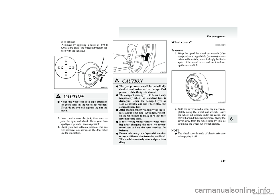
98 to 118 Nm
( Achieved by applying a force of 440 to
520 N at the end of the wheel nut wrench sup-
plied with the vehicle.)CAUTIONl Never use your foot or a pipe extension
for extra force in the wheel nut wrench.
If you do so, you will tighten the nut too
much.
13. Lower and remove the jack, then store the
jack, flat tyre, and chock. Have your dam-
aged tyre repaired as soon as possible.
14. Check your tyre inflation pressure. The cor-
rect pressures are shown on the door label.
See the illustration.
CAUTIONl The tyre pressure should be periodically
checked and maintained at the specified
pressure while the tyre is stowed.
l The compact spare tyre is to be used only
temporarily when the standard tyre is
damaged. Repair the damaged tyre as
soon as possible and use it to replace the
compact spare tyre.
l After changing the tyre and driving the ve-
hicle about 1,000 km (620 miles), retight-
en the wheel nuts to make sure that they
have not come loose.
l If the steering wheel vibrates when driv-
ing after changing the tyre, we recom-
mend you to have the tyres checked for
balance.
l Do not mix one type of tyre with another
or use a different size from the one listed.
This would cause early wear and poor han-
dling.Wheel covers* E00801300298
To remove 1.Wrap the tip of the wheel nut wrench (if so
equipped) or straight blade (or minus) screw-
driver with a cloth, insert it deeply behind a
spoke of the wheel cover, and use it to lever
up the cover a little.
2. With the cover raised a little, pry it off com-
pletely using the wheel nut wrench. Insert
the wheel nut wrench under the cover, and
move it around the circumference, prying the
cover away from the wheel little by little as
you move the wheel nut wrench around.
NOTE l The wheel cover is made of plastic; take care
when prying it off.
For emergencies
6-17
6
Page 204 of 274
CAUTIONlUse the wheel nut wrench until the wheel
cover comes completely off. If you try to
use your hands, they may be hurt by the
edge of the wheel cover.
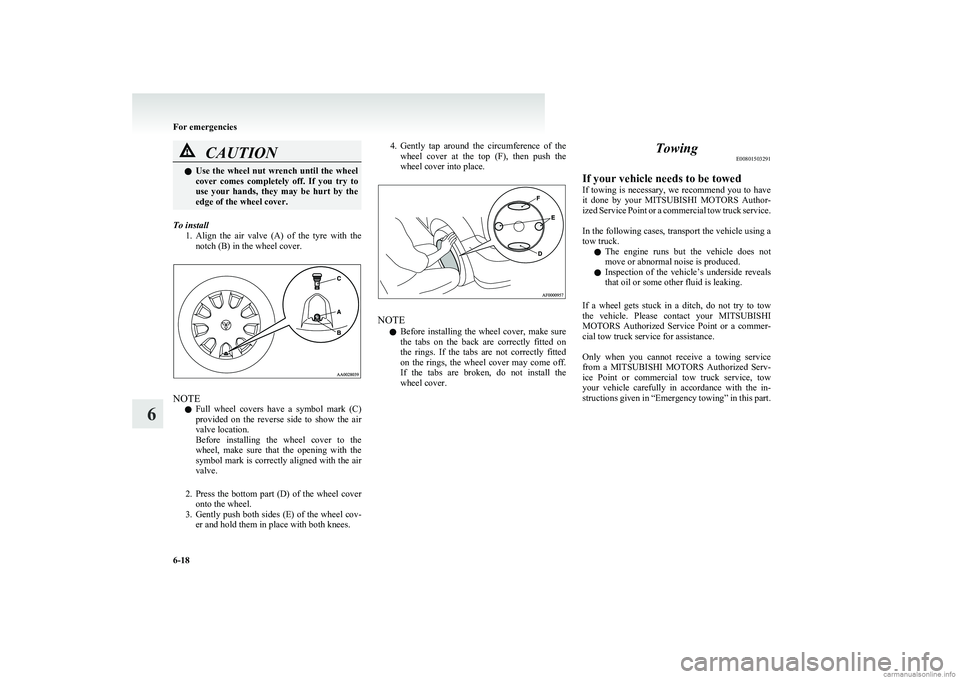
To install
1.Align the air valve (A) of the tyre with the
notch (B) in the wheel cover.
NOTE
l Full wheel covers have a symbol mark (C)
provided on the reverse side to show the air
valve location.
Before installing the wheel cover to the
wheel, make sure that the opening with the
symbol mark is correctly aligned with the air
valve.
2. Press the bottom part (D) of the wheel cover
onto the wheel.
3. Gently push both sides (E) of the wheel cov-
er and hold them in place with both knees.
4. Gently tap around the circumference of the
wheel cover at the top (F), then push the
wheel cover into place.
NOTE
l Before installing the wheel cover, make sure
the tabs on the back are correctly fitted on
the rings. If the tabs are not correctly fitted
on the rings, the wheel cover may come off.
If the tabs are broken, do not install the
wheel cover.
Towing E00801503291
If your vehicle needs to be towed
If towing is necessary, we recommend you to have
it done by your MITSUBISHI MOTORS Author-
ized Service Point or a commercial tow truck service.
In the following cases, transport the vehicle using a
tow truck.
l The engine runs but the vehicle does not
move or abnormal noise is produced.
l Inspection of the vehicle’s underside reveals
that oil or some other fluid is leaking.
If a wheel gets stuck in a ditch, do not try to tow
the vehicle. Please contact your MITSUBISHI
MOTORS Authorized Service Point or a commer-
cial tow truck service for assistance.
Only when you cannot receive a towing service
from a MITSUBISHI MOTORS Authorized Serv-
ice Point or commercial tow truck service, tow
your vehicle carefully in accordance with the in-
structions given in “Emergency towing” in this part.
For emergencies
6-18
6
Page 205 of 274
The regulations concerning towing may differ from
country to country. It is recommended that you
obey the regulations of the area where you are driv-
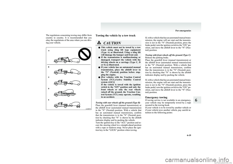
ing your vehicle.Towing the vehicle by a tow truckCAUTIONl This vehicle must not be towed by a tow
truck using sling lift type equipment
(Type A) as illustrated. Using a sling lift
will damage the bumper and front end.
l If the transmission is malfunctioning or
damaged, transport the vehicle with the
driving wheels on a carriage (Type C, D
or E) as illustrated.
l If your vehicle has an automated manual
transmission, place the allshift lever in
the “N” (Neutral) position before stop-
ping the engine.
l [
For vehicles with the Traction Control
System (TCL)/Active Stability Control
system (ASC)]
If the vehicle is towed with the ignition
switch in the “ON” position and only the
front wheels or only the rear wheels
raised off the ground, the Traction Con-
trol System (TCL) may operate, resulting
in an accident.
Towing with rear wheels off the ground (Type B)
Place the gearshift lever (manual transmission) or
the allshift lever (automated manual transmission)
in the “N” (Neutral) position. With a vehicle that
has an automated manual transmission, confirm
that the transmission is in the “N” (Neutral) posi-
tion by checking that “N” is shown by the allshift
indicator display and by pushing the vehicle.
Turn the ignition key to the “ACC” position and se-
cure the steering wheel in a straight-ahead position
with a rope or tiedown strap. Never place the igni-
tion key in the “LOCK” position when towing.
If, with a vehicle that has an automated manual trans-
mission, the engine will not start and the transmis-
sion is not in the “N” (Neutral) position, press the
brake pedal, turn the ignition switch to the “ON” po-
sition, and move the allshift lever to the “N” (Neu-
tral) position.
Towing with front wheels off the ground (Type C)
Release the parking brake.
Place the gearshift lever (manual transmission) or
the allshift lever (automated manual transmission)
in the “N” (Neutral) position. With a vehicle that
has an automated manual transmission, confirm
that the transmission is in the “N” (Neutral) posi-
tion by checking that “N” is shown by the allshift
indicator display and by pushing the vehicle.
If, with a vehicle that has an automated manual trans-
mission, the engine will not start and the transmis-
sion is not in the “N” (Neutral) position, press the
brake pedal, turn the ignition switch to the “ON” po-
sition, and move the allshift lever to the “N” (Neu-
tral) position.
Emergency towing
If towing service is not available in an emergency,
your vehicle may be temporarily towed by a rope
secured to the towing hook.
If your vehicle is to be towed by another vehicle or
if your vehicle tows another vehicle, pay careful at-
tention to the following points:
For emergencies
6-19
6
Page 206 of 274
CAUTIONlIf your vehicle has an automated manual
transmission, place the allshift lever in
the “N” (Neutral) position before stop-
ping the engine.
If your vehicle is to be towed by another vehicle
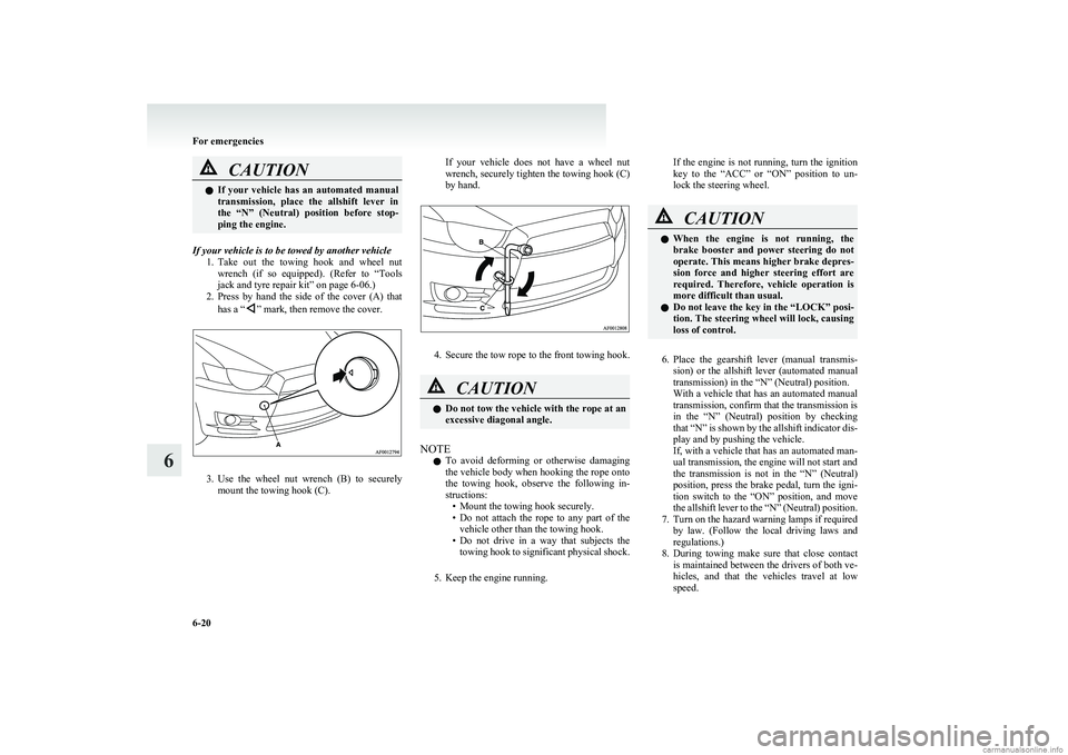
1.Take out the towing hook and wheel nut
wrench (if so equipped). (Refer to “Tools
jack and tyre repair kit” on page 6-06.)
2. Press by hand the side of the cover (A) that
has a “
” mark, then remove the cover.
3. Use the wheel nut wrench (B) to securely
mount the towing hook (C).
If your vehicle does not have a wheel nut
wrench, securely tighten the towing hook (C)
by hand.
4. Secure the tow rope to the front towing hook.
CAUTIONl Do not tow the vehicle with the rope at an
excessive diagonal angle.
NOTE
l To avoid deforming or otherwise damaging
the vehicle body when hooking the rope onto
the towing hook, observe the following in-
structions: • Mount the towing hook securely.
• Do not attach the rope to any part of the
vehicle other than the towing hook.
• Do not drive in a way that subjects the
towing hook to significant physical shock.
5. Keep the engine running.
If the engine is not running, turn the ignition
key to the “ACC” or “ON” position to un-
lock the steering wheel.CAUTIONl When the engine is not running, the
brake booster and power steering do not
operate. This means higher brake depres-
sion force and higher steering effort are
required. Therefore, vehicle operation is
more difficult than usual.
l Do not leave the key in the “LOCK” posi-
tion. The steering wheel will lock, causing
loss of control.
6. Place the gearshift lever (manual transmis-
sion) or the allshift lever (automated manual
transmission) in the “N” (Neutral) position.
With a vehicle that has an automated manual
transmission, confirm that the transmission is
in the “N” (Neutral) position by checking
that “N” is shown by the allshift indicator dis-
play and by pushing the vehicle.
If, with a vehicle that has an automated man-
ual transmission, the engine will not start and
the transmission is not in the “N” (Neutral)
position, press the brake pedal, turn the igni-
tion switch to the “ON” position, and move
the allshift lever to the “N” (Neutral) position.
7. Turn on the hazard warning lamps if required by law. (Follow the local driving laws and
regulations.)
8. During towing make sure that close contact
is maintained between the drivers of both ve-
hicles, and that the vehicles travel at low
speed.
For emergencies
6-20
6
Page 207 of 274
WARNINGlTo prevent entry of exhaust gas from the
towing vehicle, set your air selection
switch to the recirculation position.CAUTIONl The person in the vehicle being towed
must pay attention to the brake lamps of
the towing vehicle and make sure the
rope never becomes slack.
l Avoid sudden braking, sudden accelera-
tion and sharp turning; such operation
could cause damage to the towing hooks
or the tow rope.
People in the vicinity could be injured as
a result.
l When towing or being towed down a long
slope, the brakes may overheat reducing
the effectiveness. In this situation, have
your vehicle transported by a tow truck.
9. When finished towing, remove the towing
hook, and stow it in the specified location.
(Refer to “Tools jack and tyre repair kit” on
page 6-06.)
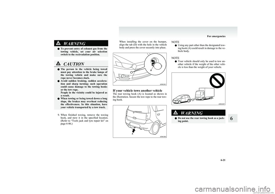
When installing the cover on the bumper,
align the tab (D) with the hole in the vehicle
body and press the cover securely into place.
If your vehicle tows another vehicle
The rear towing hook (A) is located as shown in
the illustration. Secure the tow rope to the rear tow-
ing hook.
NOTE
l Using any part other than the designated tow-
ing hook (A) could result in damage to the ve-
hicle body.
NOTE l Your vehicle should only be used to tow an-
other vehicle if the weight of the other vehi-
cle is less than the weight of your vehicle.WARNINGl Do not use the rear towing hook as a jack-
ing point.
For emergencies
6-21
6
Page 217 of 274
The catalytic converter itself gets hot quickly, and
may be damaged if overheated. The following
points should be noted in order to prevent the igni-
tion of unburned petrol within the catalytic convert-
er.
l Use UNLEADED PETROL ONLY of the
type recommended in “Fuel selection” on
page 02.
l Do not drive with an extremely low fuel lev-
el; running out of fuel could cause damage to
the catalytic converter.
l Do not attempt to start the engine by pushing
the vehicle. If the battery is weak or dis-
charged, use another battery to start the en-
gine.
l Do not idle the engine with any spark plug
wires disconnected or removed such as per-
forming diagnostic tests.
l Do not idle the engine for prolonged periods
during very rough idle or malfunctioning op-
erating conditions.
l Do not race the engine when turning off the
ignition switch. This will cause the catalytic
converter to be damaged due to contact with
unburnt fuel.
l Stop driving the vehicle if you think the per-
formance is noticeably low, or if the engine
has a malfunction such as with the ignition,
etc.
If it is impractical to stop driving immediate-
ly, reduce the speed and drive for only a
short time. We recommend you to have your
vehicle inspected as soon as possible.l In unusual situations involving grossly mal-
functioning engine operation, a burnt smell
may indicate severe and abnormal catalyst
overheating.
If this occurs, the vehicle should be stopped
in a safe place, the engine switched off and
the vehicle allowed to cool. Once the engine
is cool, a service, including a tune-up to man-
ufacturer’s specifications, should be obtained
immediately.Bonnet E01000302470
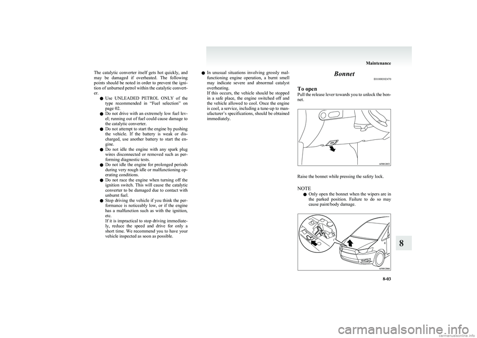
To open
Pull the release lever towards you to unlock the bon-
net.
Raise the bonnet while pressing the safety lock.
NOTE l Only open the bonnet when the wipers are in
the parked position. Failure to do so may
cause paint/body damage.
Maintenance
8-03
8
Page 226 of 274
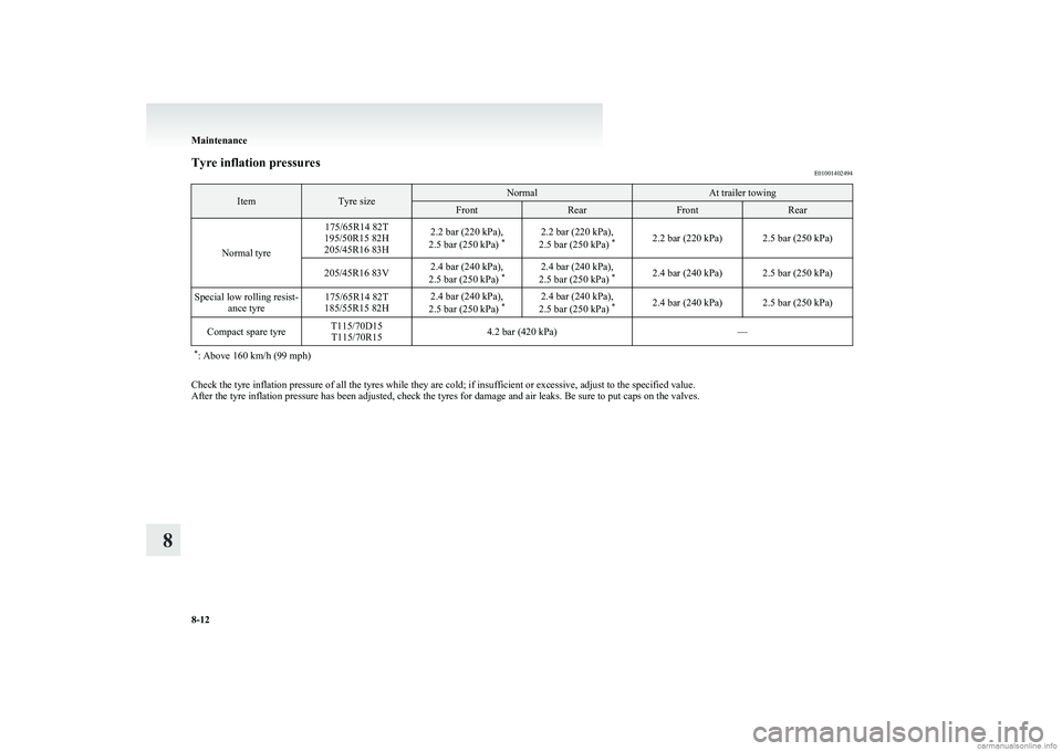
Tyre inflation pressuresE01001402494ItemTyre sizeNormalAt trailer towingFrontRearFrontRear
Normal tyre
175/65R14 82T
195/50R15 82H
205/45R16 83H2.2 bar (220 kPa),
2.5 bar (250 kPa) *2.2 bar (220 kPa),
2.5 bar (250 kPa) *2.2 bar (220 kPa)2.5 bar (250 kPa)205/45R16 83V2.4 bar (240 kPa),
2.5 bar (250 kPa) *2.4 bar (240 kPa),
2.5 bar (250 kPa) *2.4 bar (240 kPa)2.5 bar (250 kPa)Special low rolling resist-
ance tyre175/65R14 82T
185/55R15 82H2.4 bar (240 kPa),
2.5 bar (250 kPa) *2.4 bar (240 kPa),
2.5 bar (250 kPa) *2.4 bar (240 kPa)2.5 bar (250 kPa)Compact spare tyreT115/70D15
T115/70R154.2 bar (420 kPa)—* : Above 160 km/h (99 mph)
Check the tyre inflation pressure of all the tyres while they are cold; if insufficient or excessive, adjust to the specified value.
After the tyre inflation pressure has been adjusted, check the tyres for damage and air leaks. Be sure to put caps on the valves.
Maintenance
8-12
8
Page 253 of 274
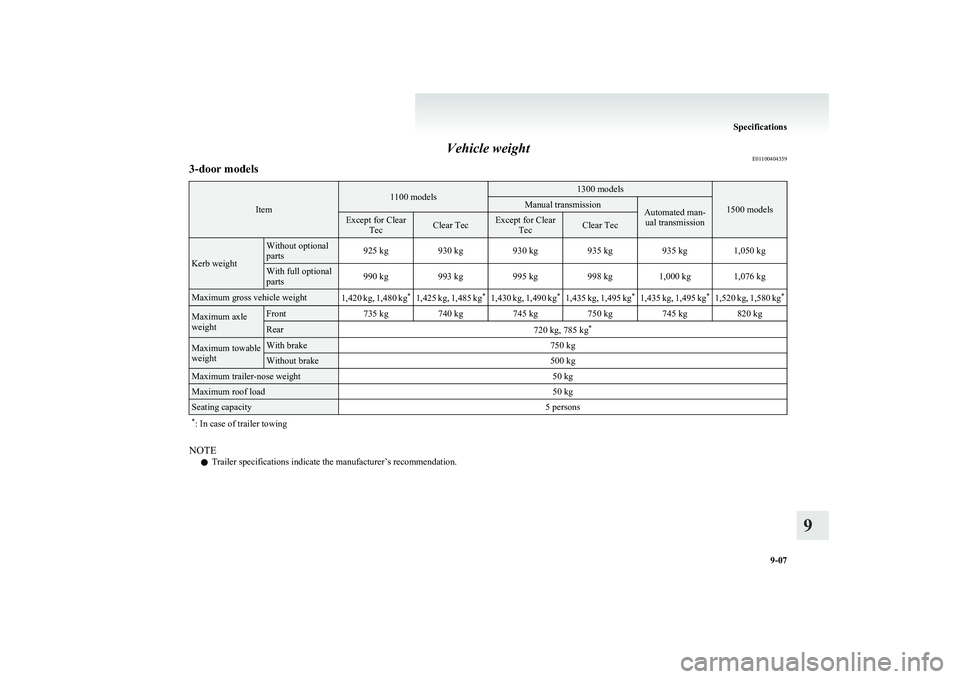
Vehicle weightE011004043593-door models
Item
1100 models1300 models
1500 models
Manual transmissionAutomated man-
ual transmissionExcept for Clear TecClear TecExcept for ClearTecClear Tec
Kerb weight
Without optional
parts925 kg930 kg930 kg935 kg935 kg1,050 kgWith full optional
parts990 kg993 kg995 kg998 kg1,000 kg1,076 kgMaximum gross vehicle weight1,420 kg, 1,480 kg *1,425 kg, 1,485 kg*1,430 kg, 1,490 kg*1,435 kg, 1,495 kg*1,435 kg, 1,495 kg*1,520 kg, 1,580 kg*Maximum axle
weightFront735 kg740 kg745 kg750 kg745 kg820 kgRear720 kg, 785 kg *Maximum towable
weightWith brake750 kgWithout brake500 kgMaximum trailer-nose weight50 kgMaximum roof load50 kgSeating capacity5 persons* : In case of trailer towing
NOTE
l Trailer specifications indicate the manufacturer’s recommendation.
Specifications
9-07
9
Page 254 of 274
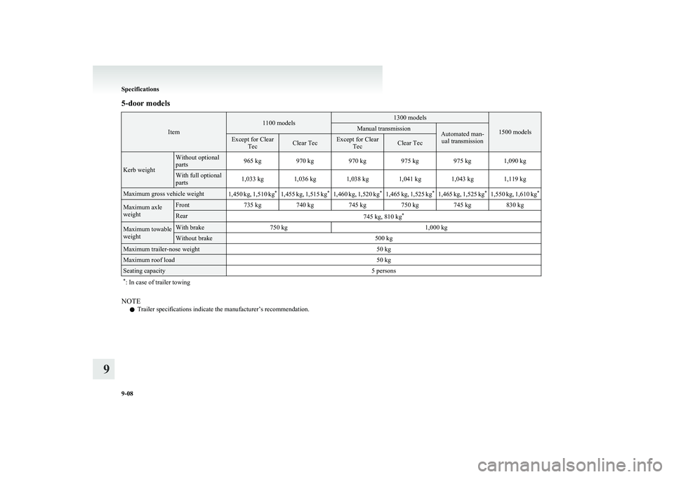
5-door models
Item
1100 models1300 models
1500 models
Manual transmissionAutomated man-ual transmissionExcept for Clear TecClear TecExcept for ClearTecClear Tec
Kerb weight
Without optional
parts965 kg970 kg970 kg975 kg975 kg1,090 kgWith full optional
parts1,033 kg1,036 kg1,038 kg1,041 kg1,043 kg1,119 kgMaximum gross vehicle weight1,450 kg, 1,510 kg *1,455 kg, 1,515 kg*1,460 kg, 1,520 kg*1,465 kg, 1,525 kg*1,465 kg, 1,525 kg*1,550 kg, 1,610 kg*Maximum axle
weightFront735 kg740 kg745 kg750 kg745 kg830 kgRear745 kg, 810 kg *Maximum towable
weightWith brake750 kg1,000 kgWithout brake500 kgMaximum trailer-nose weight50 kgMaximum roof load50 kgSeating capacity5 persons* : In case of trailer towing
NOTE
l Trailer specifications indicate the manufacturer’s recommendation.
Specifications
9-08
9
Page 268 of 274
Tailgate 1-09
Tank capacity 03
Tools 6-06 Storage 6-06
Towing 6-18
Traction control system (TCL) 4-30 Indication lamp 4-31
Trailer towing 4-36
Transmission Automated manual transmission 4-19
Manual transmission 4-16
Specifications 9-10
Turn-signal indication lamps 3-17
Turn-signal lever 3-23
Tyre repair kit 6-07
Tyres 8-11 How to change a tyre 6-15
Inflation pressures 8-12
Rotation 8-13
Size (tyre and wheel) 9-12
Snow tyres 8-14
Tyre chains 8-14
Wheel condition 8-13
U
Used engine oils safety instructions and disposal in-
formation 05
V
Vanity mirror 5-37
Vehicle care precautions 7-02
Vehicle information code plate 9-02
Vehicle labeling 9-02
Vehicle performance 9-06
Vehicle weight 9-07
Ventilators 5-02
W
Warning lamps 3-17
Washer Fluid 8-09,9-16
Switch 3-25,3-28,3-29
Washing 7-03
Waxing 7-04
Weatherstripping 8-18
Weight 9-07
Wheel Covers 6-17
Specification 9-12
Wiper Rain sensor 3-26
Rear window 3-29
Switch 3-25
Wiper blades 8-16Alphabetical index
4