door lock MITSUBISHI DIAMANTE 1900 Repair Manual
[x] Cancel search | Manufacturer: MITSUBISHI, Model Year: 1900, Model line: DIAMANTE, Model: MITSUBISHI DIAMANTE 1900Pages: 408, PDF Size: 71.03 MB
Page 5 of 408
1-6 GENERALINFORMATIONAND MAINTENANCE
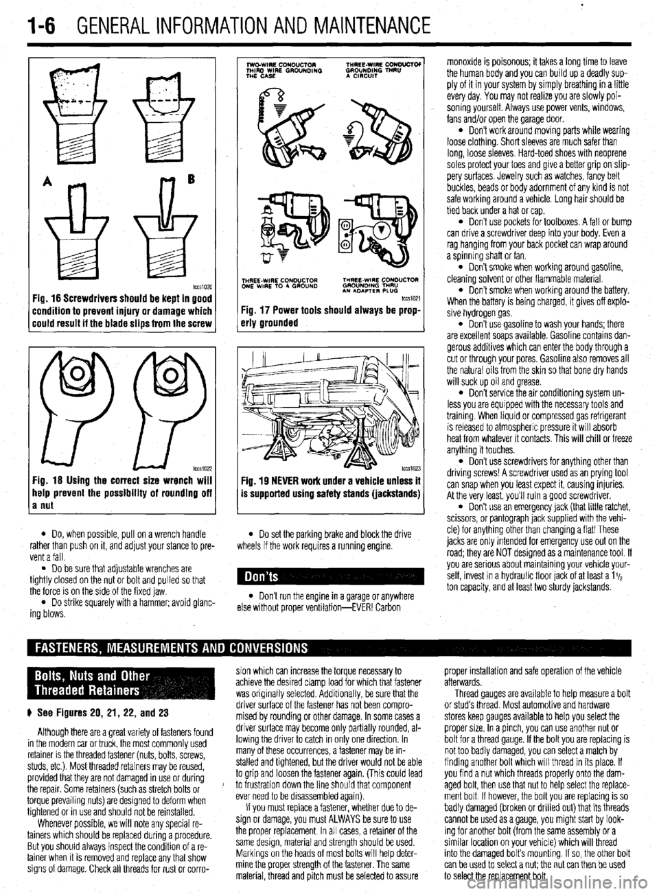
Fig. 16 Screwdrivers should be kept in good
:ondition to prevent injury or damage which
:ould result it the blade slips from the screw
0
0
PP tccs1022 Fig. 16 Using the correct size wrench will
help prevent the possibility of rounding off
a nut
7
lwo.WIRE CouDuClOR TMREE-WIRE CONO”CTOI
MIRD WIRE GROUNDING GROUNDING TNRU
THE CASE A CmxlIT
.
i$Y$$pQ
p-+
TNHREE-WIRE CONDUCTOR THREE-WIRE CONDUCTOR
ONE WIRE TO 4 GROUND GROUNOlNG TMRU
AN ADAPTER PLUG
tccm21
Fig. 17 Power tools should always be prop-
erly grounded
Fig. 19 NEVER work under a vehicle unless it
is supported using safety stands (jackstands)
l Do, when possible, pull on a wrench handle l Do set the parking brake and block the drive
rather than push on it, and adjust your stance to pre-
vent a fall. wheels if the work requires a running engine.
l Do be sure that adjustable wrenches are
tightly closed on the nut or bolt and pulled so that
the force is on the side of the fixed jaw.
l Do strike squarely with a hammer; avoid glanc-
ing blows. l Don’t run the engine in a garage or anywhere
else without proper ventilation-EVER! Carbon monoxide is poisonous; it takes a long time to leave
the human body and you can build up a deadly sup-
ply of it in your system by simply breathing in a !ittle
every day. You may not realize you are slowly poi-
soning yourself. Always use power vents, windows,
fans and/or open the garage door.
l Don’t work around moving parts while wearing
loose clothing. Short sleeves are much safer than
long, loose sleeves. Hard-toed shoes with neoprene
soles protect your toes and give a better grip on slip-
pery surfaces. Jewelry such as watches, fancy belt
buckles, beads or body adornment of any kind is not
safe working around a vehicle. Long hair should be
tied back under a hat or cap.
l Don’t use pockets for toolboxes. A fall or bump
can drive a screwdriver deep into your body. Even a
rag hanging from your back pocket can wrap around
a spinning shaft or fan.
l Don’t smoke when working around gasoline,
cleaning solvent or other flammable material.
l Don’t smoke when workrng around the battery.
When the battery is being charged, it gives off explo-
sive hydrogen gas.
l Don’t use gasoline to wash your hands; there
are excellent soaps available. Gasoline contains dan-
gerous additives which can enter the body through a
cut or through your pores. Gasoline also removes all
the natural oils from the skin so that bone dry hands
will suck up oil and grease.
l Don’t service the air conditioning system un-
less you are equipped with the necessary tools and
trainmg. When liquid or compressed gas refrigerant
is released to atmospheric pressure it will absorb
heat from whatever it contacts. This will chill or freeze
anything it touches.
l Don’t use screwdrivers for anything other than
driving screws! A screwdriver used as an prying tool
can snap when you least expect it, causing injuries.
At the very least, you’ll ruin a good screwdriver.
. Don’t use an emergency jack (that little ratchet,
scissors, or pantograph jack supplied with the vehi-
cle) for anything other than changing a flat! These
jacks are only Intended for emergency use out on the
road; they are NOT designed as a maintenance tool. If
you are serious about mamtaining your vehicle your-
self, invest in a hydraulic floor jack of at least a 1%
ton capacity, and at least two sturdy jackstands.
sion which can increase the torque necessary to proper installation and safe operation of the vehicle
achieve the desired clamp load for which that fastener afterwards.
was originally selected. Additionally, be sure that the Thread gauges are available to help measure a bolt
p See Figures 20, 21, 22, and 23 driver surface of the fastener has not been compro- or stud’s thread. Most automotive and hardware
mised by rounding or other damage. In some cases a stores keep gauges available to help you select the
Although there are a great variety of fasteners found driver surface may become only partially rounded, al- proper size. In a pinch, you can use another nut or
in the modern car or truck, the most commonly used lowing the driver to catch in only one direction. In bolt for a thread gauge. If the bolt you are replacing is
retainer is the threaded fastener (nuts, bolts, screws, many of these occurrences, a fastener may be in- not too badly damaged, you can select a match by
studs, etc.). Most threaded retainers may be reused, stalled and tightened, but the driver would not be able finding another bolt which will thread in its place. If
provided that they are not damaged in use or during to grip and loosen the fastener again. (This could lead you find a nut which threads properly onto the dam-
the repair. Some retainers (such as stretch bolts or J to frustration down the line should that component aged bolt, then use that nut to help select the replace-
torque prevailing nuts) are designed to deform when ever need to be disassembled again). ment bolt If however, the bolt you are replacing is so
tightened or in use and should not be reinstalled. If you must replace a fastener, whether due to de- badly damaged (broken or drilled out) that its threads
Whenever possible, we will note any special re- sign or damage, you must ALWAYS be sure to use cannot be used as a gauge, you might start by look-
tainers which should be replaced during a procedure. the proper replacement In all cases, a retainer of the ing for another bolt (from the same assembly or a
But you should always inspect the condition of a re- same design, material and strength should be used. similar location on your vehicle) which will thread
tainer when It is removed and replace any that show Markings on the heads of most bolts will help deter- into the damaged bolt’s mounting. If so, the other bolt
signs of damage. Check all threads for rust or corro- mine the proper strength of the fastener. The same
can be used to select a nut; the nut can then be used
material, thread and pitch must be selected to assure
to select the replacement bolt.
Page 9 of 408
.
l-10 GENERALINFORMATIONAND MAINTENANCE
which are available today will have two scales so the
The conversion factor chart is used by taking the
Standard or Metric measurements may easily be given specification and multiplying it by the neces-
taken. If any of the various measuring tools which are sary conversion factor. For instance, looking at the
available to you do not contain the same scale as first line, if you have a measurement in inches such
listed in the specifications, use the accompanying
as “free-play should be 2 in.” but your ruler reads
conversion factors to determine the proper value. only in millimeters, multiply 2 in. by the conversion factor of 25.4 to get the metric equivalent of 50.8mm.
Likewise, if the specification was given only in a Met-
ric measurement, for example in Newton Meters
(Nm), then look at the center column first. If the mea-
surement is 100 Nm, multiply it by the conversion
factor of 0.738 to get 73.8 ft. Ibs.
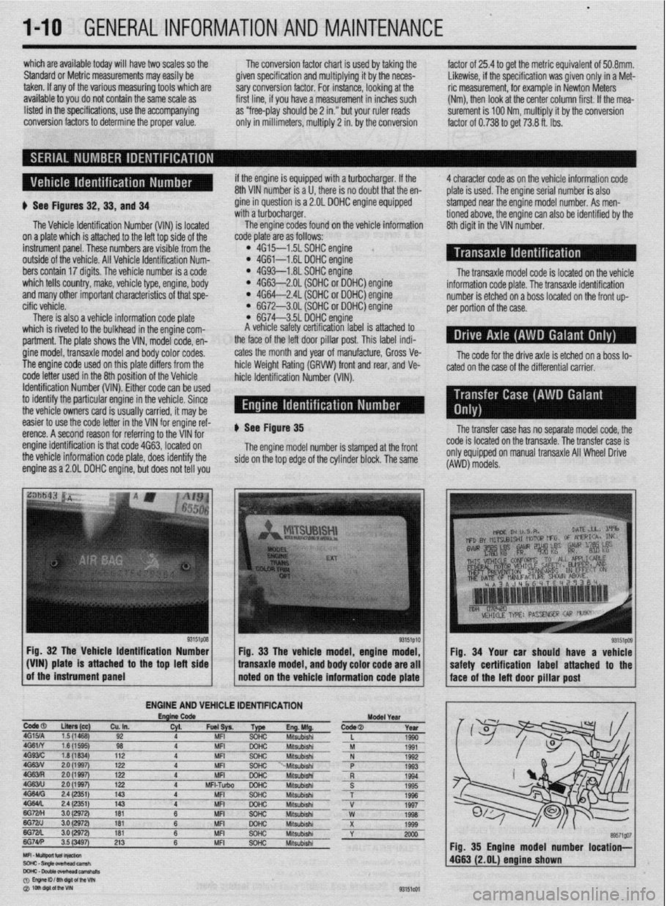
b See Figures 32,33, and 34
The Vehicle Identification Number (VIN) is located
on a plate which is attached to the left top side of the
instrument panel. These numbers are visible from the
outside of the vehicle. All Vehicle Identification Num-
bers contain 17 digits. The vehicle number is a code
which tells country, make, vehicle type, engine, body
and many other important characteristics of that spe-
cific vehicle.
There is also a vehicle information code plate
which is riveted to the bulkhead in the engine com-
partment. The plate shows the VIN, model code, en-
gine model, transaxle model and body color codes.
The engine code used on this plate differs from the
code letter used in the 8th position of the Vehicle
Identification Number (VIN). Either code can be used
to identify the particular engine in the vehicle. Since
the vehicle owners card is usually carried, it may be if the engine is equipped with a turbocharger. If the
8th VIN number is a U, there is no doubt that the en-
gine in question is a 2.OL DOHC engine equipped
with a turbocharger.
The engine codes found on the vehicle information
code plate are as follows:
l 4G15--1.5L SOHC engine l 4G61-1.6L DOHC engine l 4G93-1.8L SOHC engine l 4G63-2.OL (SOHC or DOHC) engine l 4G64-2.4L (SOHC or DOHC) engine l 6G72-3.OL (SOHC or DOHC) engine l 6G74-3.5L DOHC engine
A vehicle safety certification label is attached to
the face of the left door pillar post. This label indi-
cates the month and year of manufacture, Gross Ve-
hicle Weight Rating (GRVW) front and rear, and Ve-
hicle Identification Number (VIM). 4 character code as on the vehicle information code
plate is used. The engine serial number is also
stamped near the engine model number. As men-
tioned above, the engine can also be identified by the
8th digit in the VIN number.
The transaxle model code is located on the vehicle
information code plate. The transaxle identification
number is etched on a boss located on the front up-
per portion of the case.
The code for the drive axle is etched on a boss lo-
cated on the case of the differential carrier.
easier to use the code letter in the VIN for engine ref-
erence. A second reason for referring to the VIN for
engine identification is that code 4663, located on
the vehicle information code plate, does identify the
engine as a 2.OL DOHC engine, but does not tell you ) See Figure 35
The engine model number is stamped at the front
side on the top edge of the cylinder block. The same
Fig. 32 The Vehicle Identification Number
g3’51p’o of the instrument panel _I:^1 / Fig. 33 The vehicle model, engine model,
(VIN) plate is attached to the top left side
bansaxle model, and body color code are all
noted on the vehicle information code plate
ENGINE AND VEHiCLE IDENTlFlCATlON
EnglnCode
ModelYerr
todeal
LIten (cc)
Cu. In. W. Fuel+ Type m.hWg. Code@ Year ,G15JA 1.5 (1468) 92 4 MFI SOHC Mitsubishi
L 1990
IG61N 1.6(15QQ) 98 4 MFI DOHC
Mitsubishi M 1991
1G93lC 1.8 (1834) 112 4 MFI SOHC Mitsubishi N 1992
IG63N 2.0 (1997) 122 4 MFI SOHC “-Mitsubishi P
1993
!G63Fi 2.0 (1997) 122 4 MFI DOHC Mitsubishi
R 1994
,G63iU 2.0 (1997) 122 4 MFI-Tuibo DOHC Mitsubishi
S 1995
.GMffi 2.4 (2351) 143 4 MFI SOHC
Mitsubishi T 1996
iG64L 2.4 (2351) 143 4 MFI DOHC Mitsubishi V
lEzH 3.0 1997
(2972) 161 6 MFI SOHC Mitsubishi W 1998
;G7ZJ 3.0 (2Q72) 161 6 MFI GQHC Mitsubishi
~.. X 1999
iG7zL 3.0 (2972) 181
~ 6 MFI SOHC ___-___ Miisubishi
Y 2000
iG74lP 3.5 (3497) 213 6 MFI SOHC Miisubishi
The transfer case has no separate model code, the
code is located on the transaxle. The transfer case is
onlv eoUiODed on manual transaxle All Wheel Drive
(AWD)‘mbdels.
Fig. 34 Your car should have a vehicle
Fig. 35 Engine model number location-
4663 (2.OL) engine shown
Page 29 of 408
.
l-30 GENERAL'INFORMATIONAND MAINTENANCE
n Pylon@ inserts, the clip
be removed prior to siidi then the insert can be re
After installing the replacement
strip and pull up while twisting counterclockwise.
The backing strip will snap out of the retaining tab.
Do this for the remaining tabs until the refill is free of
the blade. The length of these refills is molded into
the end and they should be replaced with identical
types. cate the front end is out of alignment or that the tires
are out of balance.
TIRE ROTATION
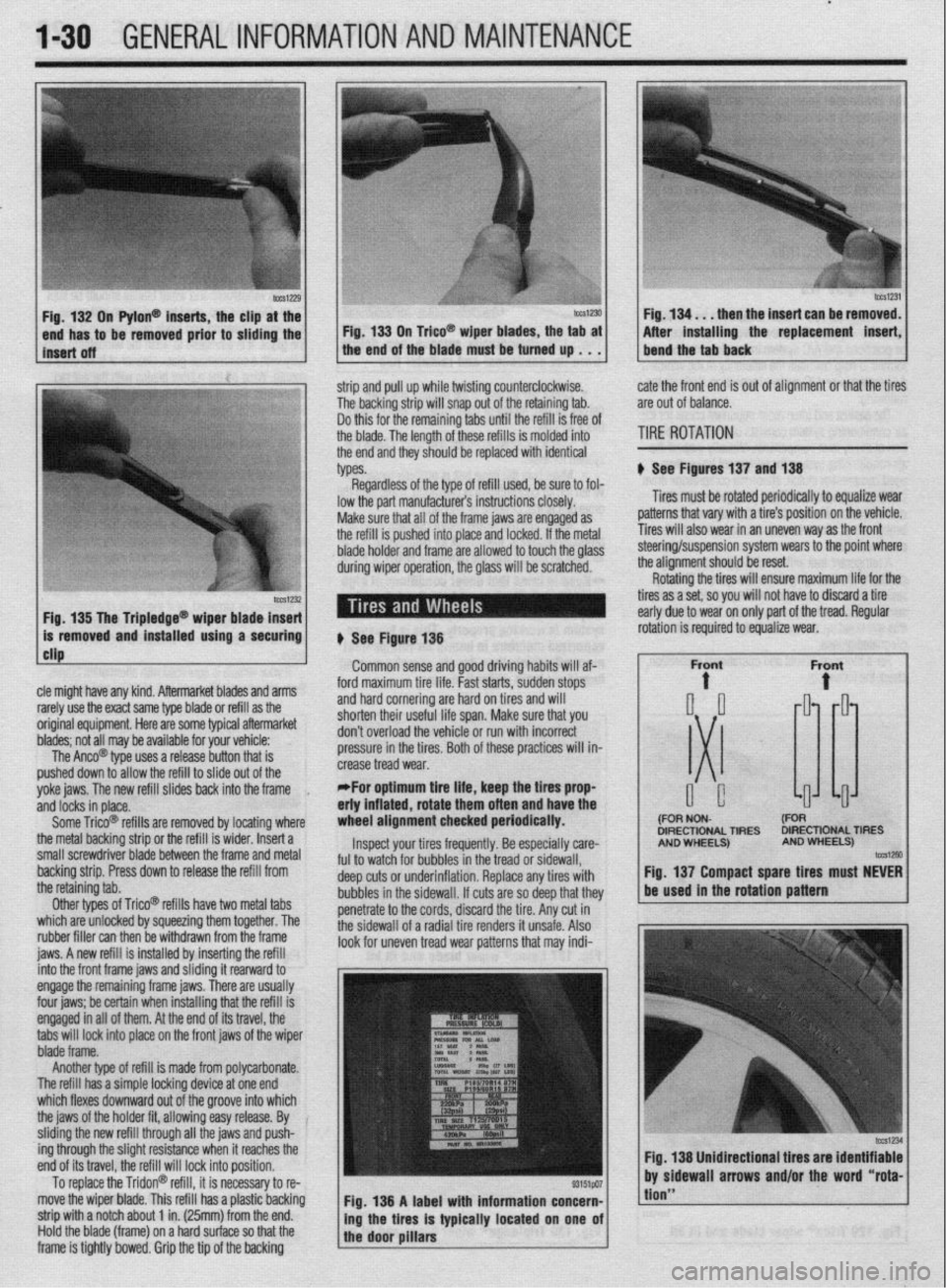
# See Figures 137 and 138
Tires must be rotated periodically to equalize wear
patterns that vary with a tire’s position on the vehicle.
Tires will also wear in an uneven way as the front
1 Fin 1% Tha Trinlarlna@
cle might have any kind. Aftermarket blades and arms
rarely use the exact same type blade or refill as the
original equipment. Here are some typiel aftermarket
blades; not all may be available for your vehicle:
The Anco@ type uses a release button that is
pushed down to allow the refill to slide out of the
yoke jaws. The new refill slides back into the frame
,
and locks in place.
Some Trico@ refills are removed by locating where
the metal backing strip or the refill is wider. Insert a
small screwdriver blade between the frame and metal
backing strip. Press down to release the refill from
the retaining tab.
Other types of Trico@’ refills have two metal tabs
which are unlocked by squeezing them together. The
rubber filler can then be withdrawn from the frame
iaws. A new refill is installed bv insertina the refill lowed to touch the olass steering/suspension system wears to the point where
the alianment should be reset.
# See Figure 138
Common sense and good driving habits will af-
ford maximum tire life. Fast starts, sudden stops
and hard cornering are hard on tires and will
shorten their useful life span. Make sure that you
don’t overload the vehicle or run with incorrect
pressure in the tires. Both of these practices will in-
crease tread wear.
*For optimum tire life, keep the fires prop
eriy inflated, rotate them often and have the
wheel alignment checked periodically.
Inspect your tires frequently. Be especially care-
ful to watch for bubbles in the tread or sidewall,
deep cuts or underinflation. Replace any tires with
bubbles in the sidewall. If cuts are so deep that they
penetrate to the cords, discard the tire. Any cut in
the sidewall of a radial tire renders it unsafe. Also
look for uneven tread wear patterns that may indi- Rotating the tires will ensure maximum life for the
tires as a set, so you will not have to discard a tire
early due to wear on only part of the tread. Regular
DIRECTIONAL TIRES DIRECTIONAL TIRES
jnto the front frame jaws and &ding it rearward to
engage the remaining frame jaws. There are usually
four jaws; be certain when installing that the refill is
engaged in all of them. At the end of its travel, the
tabs will lock into place on the front jaws of the wiper
blade frame.
Another type of refill is made from polycarbonate.
The refill has a simple locking device at one end
which flexes downward out of the groove into which
the jaws of the holder fit, allowing easy release. By
sliding the new refill through all the jaws and push-
ing through the slight resistance when it reaches the
end of its travel, the refill will lock into position.
To replace the Tridon@ refill, it is necessary to re-
move the wiper blade. This refill has a plastic backing
strip with a notch about 1 in. (25mm) from the end.
Hold the blade (frame) on a hard surface so that the
frame is tightly bowed. Grip the tip of the backing Fig. 138 A label with information concern-
ing the tires is typically located on one of
the door pillars
tion”
Page 42 of 408
GENERALINFORMATIONAND MAINTENANCE l-43
l Special car washing detergent is the best to
use. Liquid dishwashing detergent can remove wax
and leave the car’s paint unprotected and in addition
some liquid detergents contains abrasives which can
scratch the paint.
l Bird droppings should be removed from the
paintwork as soon as possible, otherwise the finish
may be permanently stained.
When the car is driven immediately after be-
ing washed, apply the brakes several times
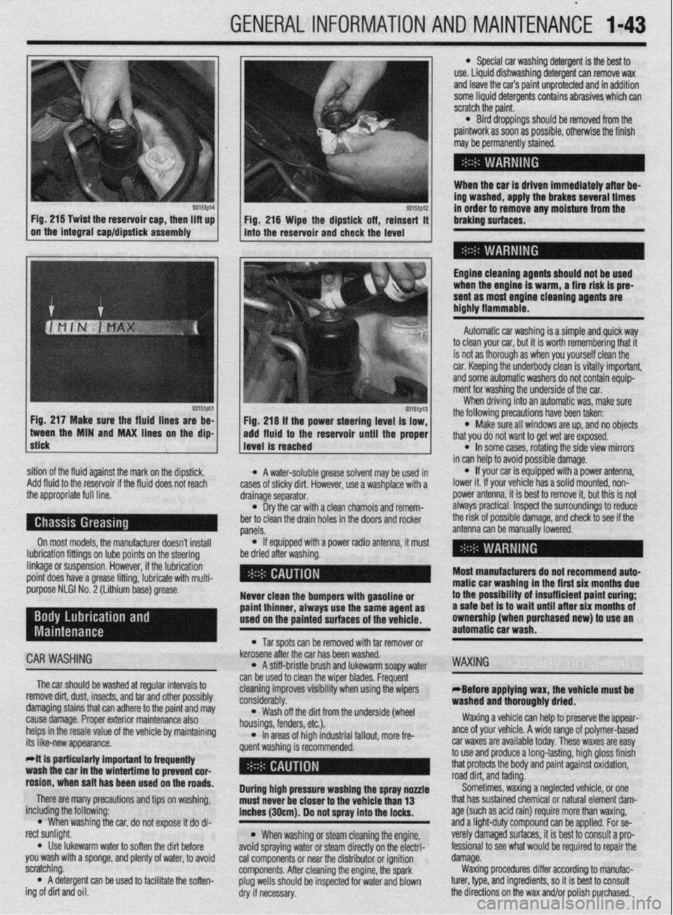
93151p14 93151p12 Fig. 215 Twist the reservoir cap, then lift up
I I
in order to remove any moisture from the
Fig. 216 Wipe the dipstick off, reinsert it braking surfaces.
on the integral cap/dipstick assembly
into the reservoir and check the level
I
Engine cleaning agents should not be used
when the engine is warm, a fire risk is pre-
sent as most engine cleaning agents are
highly flammable.
sition of the fluid against the mark on the dipstick,
Add fluid to the reservoir if the fluid does not reach
the appropriate full line.
On most models, the manufacturer doesn’t install
lubrication fittings on lube points on the steering
linkage or suspension. However, if the lubrication
point does have a grease fitting, lubricate with multi-
purpose NLGI No. 2 (Lithium base) grease.
CAR WASHING
The car should be washed at regular intervals to
remove dirt, dust, insects, and tar and other possibly
damaging stains that can adhere to the paint and may
cause damage. Proper exterior maintenance also
helps in the resale value of the vehicle by maintaining
its like-new appearance.
Mt is particularly important ta frequentiy
wash the car in the wintertime to prevent cor-
rosion, when salt has been used on the roads.
There are many precautions and tips on washing,
including the following:
l When washing the car, do not expose it do di-
rect sunlight.
. Use lukewarm water to soften the dirt before
you wash with a sponge, and plenty of water, to avoid
scratching.
l A detergent can be used to facilitate the soften-
ing of dirt and oil. * A water-soluble grease solvent may be used in
cases of sticky dirt. However, use a washplace with a
drainage separator.
l Dry the car with a clean chamois and remem-
ber to clean the drain holes in the doors and rocker
panels.
l If equipped with a power radio antenna, it must
be dried after washing.
Never clean the bumpers with gasoline or
paint thinner, always use the same agent as
used on the painted surfaces of the vehicle.
l Tar spots can be removed with tar remover or
kerosene after the car has been washed.
l A stiff-bristle brush and lukewarm soapy water
can be used to clean the wiper blades. Frequent
cleaning improves visibility when using the wipers
considerably.
l Wash off the did from the underside (wheel
housings, fenders, etc.).
l In areas of high industrial fallout, more fre-
quent washing is recommended.
During high pressure washing the spray nonle
must never be closer to the vehicle than 13
inches (30cm). Do not spray into the locks.
l When washing or steam cleaning the engine,
avoid spraying water or steam directly on the electri-
cal components or near the distributor or ignition
components. After cleaning the engine, the spark
plug wells should be inspected for water and blown
dry if necessary. Automatic car washing is a simple and quick way
to clean your car, but it is worth remembering that it
is not as thorough as when you yourself clean the
car. Keeping the underbody clean is vitally important,
and some automatic washers do not contain equip-
ment for washing the underside of the car.
When driving into an automatic was, make sure
the following precautions have been taken:
l Make sure all windows are up, and no objects
that you do not want to get wet are exposed.
l In some cases, rotating the side view mirrors
in can help to avoid possible damage.
l If your car is equipped with a power antenna,
lower it. If your vehicle has a solid mounted, non-
power antenna, it is best to remove it, but this is not
always practical. Inspect the surroundings to reduce
the risk of possible damage, and check to see if the
antenna can be manually lowered.
Most manufacturers do not recommend auto-
matic car washing in the first six months due
to the possibility of insufficient paint curing;
a safe bet is to wait until after six months of
ownership (when purchased new) to use an
automatic car wash.
WAXING
eBefore applying wax, the vehicle must be
washed and thoroughly dried.
Waxing a vehicle can help to preserve the appear-
ante of your vehicle. A wide range of polymer-based
car waxes are available today. These waxes are easy
to use and produce a long-lasting, high gloss finish
that protects the body and paint against oxidation,
road dirt, and fading.
Sometimes, waxing a neglected vehicle, or one
that has sustained chemical or natural element dam-
age (such as acid rain) require more than waxing,
and a light-duty compound can be applied. For se-
verely damaged surfaces, it is best to consult a pro-
fessional to see what would be required to repair the
damage.
Waxing procedures differ according to manufac-
turer, type, and ingredients, so it is best to consult
the directions on the wax and/or polish purchased.
Page 43 of 408
1-44 GENERALINFORMATIONAND MAINTENANCE
INTERIOR CLEANING
Upholstery
Fabric can usually be cleaned with soapy water or
a proper detergent. For more difficult spots caused by
oil, ice cream, soda, etc., use a fabric cleaner avail-
able at most parts stores. Be sure when purchasing
the cleaner to read the label to ensure it is safe to use
on your type of fabric. A safe method of testing the
cleaner is to apply a small amount to an area usually
unseen, such as under a seat, or other areas. Wart a
while, perhaps even a day to check the spot for fad-
ing, discoloring, etc., as some cleaners will only
cause these problems after they have dried
Leather upholstery requrres special care, it can be
cleaned with a mild soap and a soft cloth. It is recom-
mended that a special leather cleaner be used to
clean but also treat the leather surfaces in your vehi-
cle. Leather surfaces can age quickly and can crack if
not properly taken care of, so it is vital that the leather
surfaces be maintained.
Floor Mats and Carpet
The floor mats and carpet should be vacuumed or
brushed regularly. They can be cleaned with a mild
soap and water. Special cleaners are available to
clean the carpeted surfaces of your vehicle, but take
care in choosing them, and again it is best to test
them in a usually unseen spot.
Dashboard, Console, Door Panels, Etc.
The dashboard, console, door panels, and other
plastic, vinyl, or wood surfaces can be cleaned using
a mild soap and water. Caution must be taken to keep
water out of electronic accessories and controls to
avoid shorts or ruining the components Again spe-
cial cleaners are available to clean these surfaces, as
with other cleaners care must taken in purchasmg
and using such cleaners.
There are protectants available which can treat the
various surfaces in your car giving them a “shiny new
look”, however some of these protectants can cause
more harm than good in the long run. The shine that
is placed on your dashboard attracts sunlight accel-
erating the aging, fading and possibly even cracking
the surfaces. These protectants also attract more dust
to stick to the surfaces they treat, Increasing the cleaning you must do to maintain the appearance of
your vehicle. Personal discretion is advised here.
On most models covered by this manual, the
wheel bearmgs used are sealed units and do not re-
quire routine maintenance. However on some Galant
and Mirage models, the rear wheel bearing do require
periodic repacking. For removal and installation in-
structions, please refer to Section 7 (for rear bear-
ings) or Section 8 (for front bearings).
REPACKING
*Sodium based grease is not compatible
with lithium based grease. Read the package
labels and be careful not to mix the two
types. If there is any doubt as to the type of
grease used, completely clean the old
grease from the bearing and hub before re-
placing.
Before handling the bearings, there are a few
things that you should remember to do and not to do.
DO the following: l Remove all outside dirt from the housing be-
fore exposing the bearing.
l Treat a used bearing as gently as you would a
new one.
l Work with clean tools in clean surroundings. l Use clean, dry gloves, or at least clean, dry
hands.
l Clean solvents and flushing fluids are a must. l Use clean paper when laying out the bearings
to dry.
l Protect drsassembled bearings from rust and
dirt. Cover them up.
l Use clean, lint-free rags to wipe the bearings. l Keep the bearings in oil-proof paper when they
are to be stored or are not in use.
l Clean the inside of the housing before replac-
ing the bearin
Do NOT do he followino: El, l Do not work in dirty sirroundings. l Do not use dirty, chipped or damaged tools. l Do not work on wooden work benches or use
wooden mallets.
l Do not handle bearings with dirty or moist
hands.
l Do not use gasoline for cleaning. Use a safe
solvent.
l Do not spin dry bearings with compressed air.
They will be damaged.
l Do not use cotton waste or dirty cloths to wipe
bearings.
l Do not scratch or nick bearing surfaces. l Do not allow the bearina to come in contact
” with dirt or rust at any time.
The rear wheel bearinas on some Galant and Mi-
rage models require periodic maintenance. A pre-
mium high melting point grease meeting Grade
Multipurpose Grease NLGI Grade #2 or equivalent
must be used. Long fiber type greases must not be
used. This service is recommended every 30,000
miles (48,000 km).
*For information on Wheel Bearing removal
and installation, refer to Section 7 of this
manual.
1. Remove the wheel bearing.
2. Clean all parts in a non-flammable solvent and
let them air dry.
*Only use lint-free rags to dry the bearings.
Never spin-dry a bearing with compressed
air, as this will damage the rollers.
3. Check for excessive wear and damage. Replace
the bearing as necessary.
*Packina wheel bearinos with arease is
best accomplished by u&g a wheel bearing
packer (available at most automotive parts
stores).
4. If a wheel bearing packer is not available, the
bearings may be packed by hand.
a. Place a “healthy’ glob of grease in the
palm of one hand.
b. Force the edge of the bearing into the
grease so that the grease fills the space between
the rollers and the bearing cage.
c. Keep rotating the bearing while continuing
to push the grease through.
d. Continue until the grease is forced out the
other side of the bearing.
5. Place the packed bearing on a clean surface
and cover it until it is time for installation.
6. Install the wheel bearing.
# See Figures 219 and 220
To prevent the bumper from deforming, these vehi-
cles cannot be towed by a wrecker using sling-type
equipment. If these vehicles require towing, use a
wheel lift or flat bed equipment. It is recommended
that the vehicle be towed from the front If a flat bed is
not available.
Manual transaxle vehicles may be towed from the
rear provided that the transaxle is in Neutral and the
driveline has not been damaged. The steering wheel
must be clamped in the straight-ahead positron with a
steering wheel clamping device designed for towing
service use.
Do not use the steering column lock to secure
the front wheel uosition for towina.
Automatic transaxle vehicles may be towed on the
front wheels at speeds not to exceed 30 mph (50
km/h) for a distance not to exceed 18 miles (30 km).
If these limits can not be met, then the front wheels
must be placed on a tow dolly.
# See Figure 221
All Wheel Drive (AWD) vehicles should only be
towed with all 4 wheels on the ground or lifted from
the road surface. This means that the vehicle is to be
towed either with flatbed equipment, with all wheels
on dollies or flat towed. Damage to the viscous cou-
pling may result if the vehicle is towed with only 2
wheels on the ground.
p See Figure 222
Whenever a vehicle is jump started, precautions
must be followed In order to prevent the possibility of
Page 223 of 408
.
6-20 CHASSIS ELECTRICAL
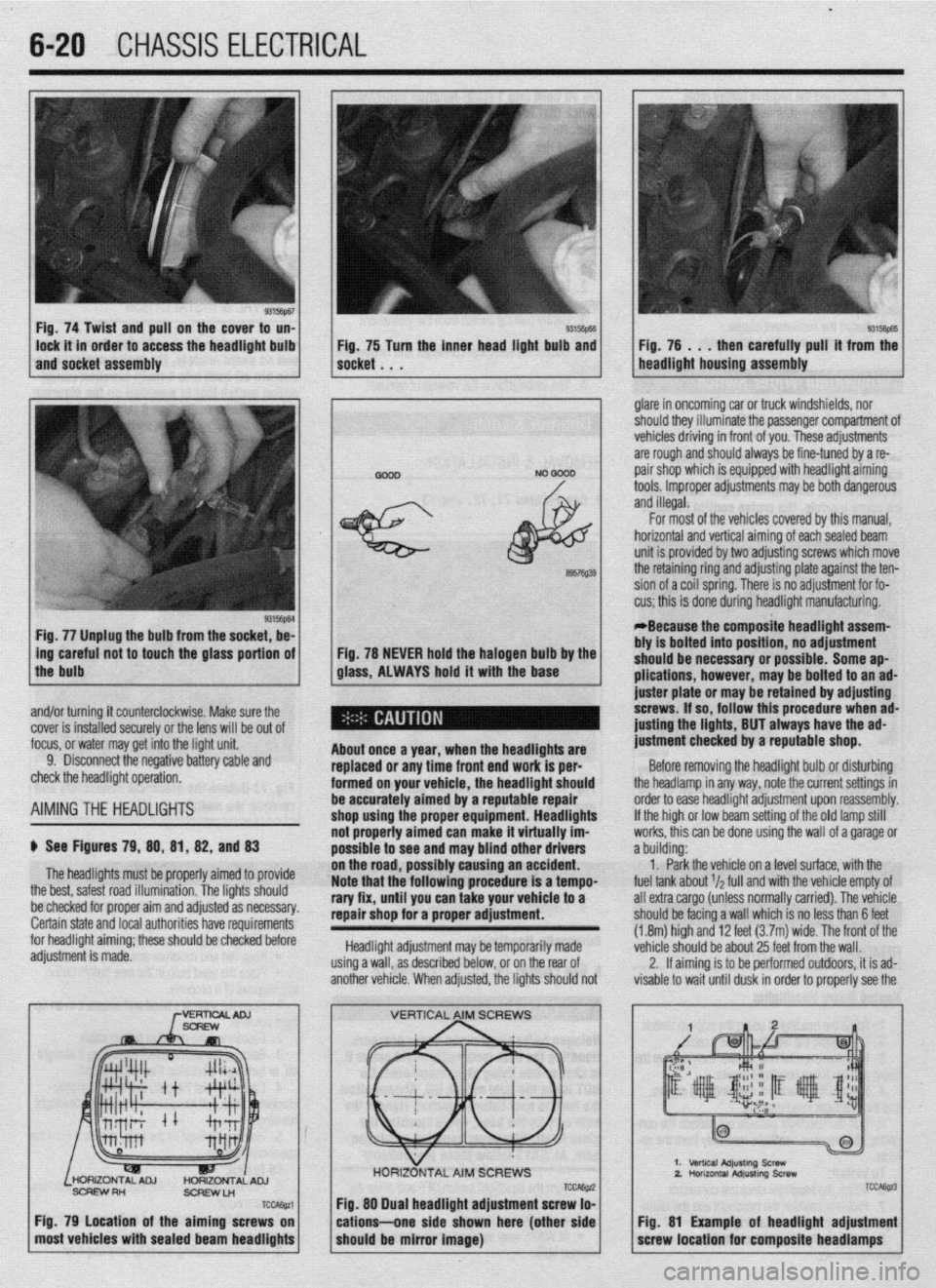
Fig. 74 Twist and pull on the cover to un-
lock it in order to access the headlight bulb
and socket assembly 93Mm Fig, 75 Turn the inner head light bulb and then carefully pull’ it from the
NO 0000 . glare in oncoming car or truck windshields, nor
should they illuminate the passenger compartment of
vehicles driving in front of you. These adjustments
are rough and should always be fine-tuned by a re-
pair shop which is equipped with headlight aiming
tools. Improper adjustments may be both dangerous
and illegal.
Fig. 77 Unplug the bulb from the socket, be-
L
ing careful not to touch the glass portion of
the bulb
I
6957Q39
Fig. 78 NEVER hold the halogen bulb by the
glass, ALWAYS hold it with the base
,
About once a year, when the headllgftts are
replaced or any time front end work is per-
formed on your vehicle, the headlight should
be accurately aimed by a reputable repair
shop uslng the proper equipment. Headlights
not properly aimed can make it virtually im-
possible to see ar Id may blind other drivers
ibly causing an accident.
Note that the’following procedure is a tempo-
rary fix, until you can take your vehicle to a
repair shop for a proper adjustment.
Headlight adjustment may be temporarily made
using a wall, as described below, or on the rear of
another vehicle. When adjusted, the lights should not For most of the vehicles covered by this manual,
horizontal and vertical aiming of eachsealed beam
unit is provided by two adjusting screws which move
the retaining ring and adjusting plate against the ten-
sion of a coil spring. There is no adjustment for fo-
cus; this is done during headlight manufacturing.
*Because the composite headlight assem-
bly is bolted into position, no adjustment
should be necessary or possible. Some ap-
plications, however, may be bolted to an ad-
juster plate or may be retained by adjusting
screws. If so, follow this procedure when ad-
@sting the lights, BUT always have the ad-
justment checked by a reputable shop.
Before removing the headlight bulb or disturbing
the headlamp in any way, note the current settings in
order to ease headlight adjustment upon reassembly.
If the high or low beam setting of the old lamp still
works, this can be done using the wall of a garage or
a building:
1. Park the vehicle on a level surface, with the
fuel tank about r/a full and with the vehicle empty of
all extra cargo (unless normally carried). The vehicle
should be facing a wall which is no less than 6 feet
(1.8m) high and 12 feet (3.7m) wide. The front of the
vehicle should be about 25 feet from the wall.
2. If aiming is to be performed outdoors, it is ad-
visable to wait until dusk in order to properly see the
% and/or turning it counterclockwise. Make sure the
cover is installed securely or the lens will be out of
focus, or water may get into the light unit.
9. Disconnect the negative battery cable and
check the headlight operation.
AIMINGTHE HEADLIGHTS
$ See Figures 79, 88, 81, 82, and 83
The headlights must be proper’ ’ ’ ’
the best, safest road illumination. ’ ’
ly armea IO provrae
The lights should
:.__1__1 __ - -___-_-. on the road, POSSI
be checked for proper aim and adfusreu as IlweSYdly. Certain state and local authorities have requirements
for headlight aiming; these should be checked before
adjustment is made.
SCFEWRH
ScFlEwLn
TCcAssa
Fig. 79 Location of the aiming screws on
most vehicles with sealed beam headlights
TCCAE@ Fig. 88 Dual headlight adjustment screw lo-
cations--one side shown here (other side
should be mirror image)
2.
TCC&z3
Fig. 81 Example of headlight adjustment
screw location for composite headlamps
Page 232 of 408
CHASSIS ELECTRlCiL 6-29
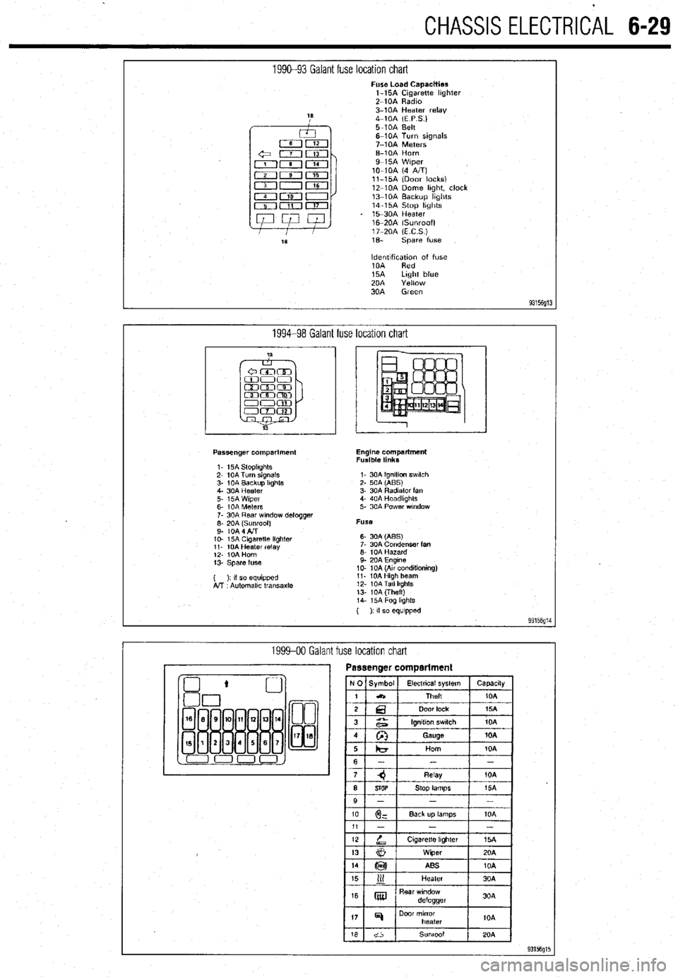
1990-93 Galant fuse location chart Fuse Load Capacities
l-15A Cigarette hghter
Z-10A Radm
3-10A Heater relay
4-10A (E P S.)
5-10A Belt
6-10A Turn signals
7-10A Meters
6-10A Horn
9-15A Wiper
lo-10A (4 A/T)
ll-15A (Door locks)
12-10A Dome hght, clock
13-10A Backup hghts
14-15A Stop hghts
15-30A Heater
16m20A (Sunroof)
17-20A (ECS)
1% spare fuse
ldentlfxation of fuse
10A Red
15A Light blue
20A Yellow
30A Green
93156g13
1994-98 Galant fuse location chart
Passenger compartment
1. 15A StoplIghts
2- 10A Turn signals
3- 1 OA Backup Itghts
4. 30A Heater
5. i5A Wiper
6- IOA Meters
7. 30A Rear wndow defogger
;: fo& fl$oof)
IO- 15A Cagaretle lighler
11. 10A Heater relay
12. IOA Horn
13. Spare fuse
( ): II so equipped
A!T Automallc transaxle Engine compartment
Fusible links
I- 30A Ignition swlch
2. 50A (ABS)
3. 30A Radiator fan
4. 40A Headkghts
5. 30A Power wndow
Fuse
6- 30A (ABS)
7. 30A Condenser fan
6. 10A Hazard
9. 20A Engine
10. 10A (Au conditioning)
11. 10AHigh beam
12. 10ATall lkghts
13. 10A (Theft)
14. i5A Fog lkghls
( ): If so equipped
93156g14
1999-00 Galant fuse location chart
Page 233 of 408
6-30 CHASSIS ELECTRICAL
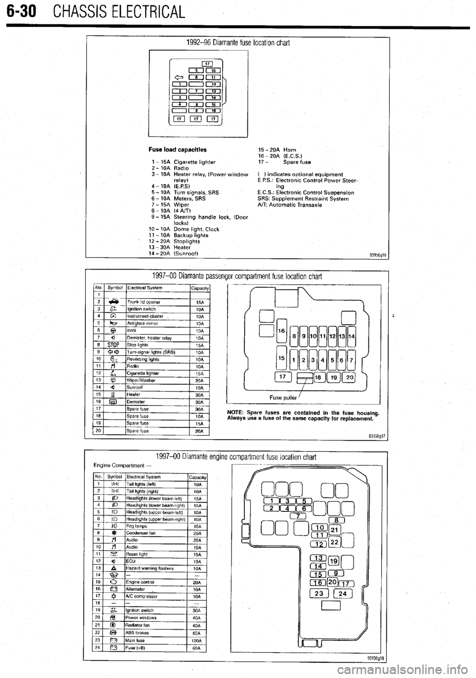
1992-96 Diamante fuse location chart
I
Fuse load caaacities 15 -2OA Horn
16 - 20A (E.C.S.)
1 - 15A Cigarette lighter 17 - spare fuse
2 - 10A Radio
3 - 10A Heater relay, (Power window ( ) indicates optlonal equipment
relay) E P.S.: Electronic Control Power Steer-
4 - 10A (E.P.S) ing
5 - 10A Turn signals, SRS E.C.S.: Electronic Control Suspension
6 - 10A Meters, SRS SRS~ Supplement Restratnt System
7 - 15A Wiper A/T: Automatic Transaxle
8-10A (4AIT)
9- 15A Steering handle lock, (Door
locks)
lo- 10A Dome light, Clock
11 - 10A Backup lights
12 -2OA StoplIghts
13 -3OA Heater
14 - 20A (Sunroof)
93156fllE
1997-00 Diamante passenger compartment fuse location chart No Symbol Electrical System
I capactty
I
Spare fuses are contained in the fuse housing
use a fuse of the same capacity for replacement.
199740 Diamante encline
compartment fuse location chart
Page 235 of 408

6-32 CHASSIS ELECTRICAL
INDEX OF WIRING DIAGRAMS
DIAGRAM 28 1990-93 Galant Wipers Chassis Schematics
DIAGRAM 29 1990-93 Galant Wipers w/ ETACS Control Unit Chassis Schematics
DIAGRAM 30 1990-93 Galant Power Door Locks Chassis Schematics
DIAGRAM 31 1990-93 Galant Power Door Locks wl ETACS Control Unit Chassis Schematics
DIAGRAM 32 1996-00 Galant Starting System Chassis Schematics
DIAGRAM 33 1994-00 Galant Charging System Chassis Schematics
DIAGRAM 34 1994-00 Galant Charging System Chassis Schematics
DIAGRAM 35 1994-00 Galant Headlights Chassis Schematics
DIAGRAM 36 1994-00 Galant Taillights Chassis Schematics
DIAGRAM 37 1994-00 Galant Brake Lights/Backup Lights/Horn Chassis Schematics
DIAGRAM 38 1994-00 Galant Turn Signal Chassis Schematics
DIAGRAM 39 1994-00 Galant Power Windows Chassis Schematics
m
DIAGRAM 40 1994-00 Galant Wipers Chassis Schematics
b
DIAGRAM 41 1994 Galant Power Door Locks w/ ETACS Control Unit Chassis Schematics
DIAGRAM 42 1994-00 Galant Power Door Locks Chassis Schematics
DIAGRAM 43 1992-00 Diamante Starting System Chassis Schematics
DIAGRAM 44 1992-00 Diamante Charging System Chassis Schematic
DIAGRAM 45 1992-93 Diamante Cabling System Chassis Schematic
DIAGRAM 46 1994-95 Diamante Cooling System Chassis Schematics
DIAGRAM 47 1996-00 Diamante Headlights Chassis Schematics
DIAGRAM 48 1992-95 Diamante Taillights/Backup Lights Chassis Schematics
DIAGRAM 49 1992-95 Diamante Turn Signal Chassis Schematics
DIAGRAM 50 1992-00 Diamante Brake Lights, Horn Chassis Schematic
DIAGRAM 51 1992-95 Diamante Power Windows Chassis Schematics
DIAGRAM 52 1992-95 Diamante Wipers Chassis Schematics
DIAGRAM 53 1992-93 Diamante Power Door Locks Chassis Schematics
Page 236 of 408

CHASSIS ELECTRlCiL 6-33
INDEX OF WIRING DIAGRAMS
DIAGRAM 54
DIAGRAM 55
DIAGRAM 56
DIAGRAM 57
DIAGRAM 58
DIAGRAM 59
DIAGRAM 60
DIAGRAM 61
DIAGRAM 62
DIAGRAM 63
DIAGRAM 64
DIAGRAM 65
DIAGRAM 66
DIAGRAM 67
DIAGRAM 68
DIAGRAM 69
DIAGRAM 70
DIAGRAM 71
DIAGRAM 72
DIAGRAM 73
DIAGRAM 74
DIAGRAM 75
DIAGRAM 76
DIAGRAM 77 1994-95 Diamante Power Door Locks Chassis Schematics
1996-00 Diamante Cooling System Chassis Schematics
1996-00 Diamante Taillights Chassis Schematics
1996-00 Diamante Turn Signal Chassis Schematics
1996-00 Diamante Power Windows Chassis Schematics
1996-00 Diamante Power Door Locks Chassis Schematics
1992-95 Diamante Headlights Chassis Schematics
1996-00 Diamante Wipers Chassis Schematics
1993-96 Mirage Charging System Chassis Schematics
1993 Mirage 1.5L Cooling System Chassis Schematics
1994-96 Mirage 1.5L Cooling System Chassis Schematics
1993 Mirage 1.8L Cooling System Chassis Schematics
1994-96 Mirage 1.8L Cooling System Chassis Schematics
1993-96 Mirage Headlights Chassis Schematics
1993-96 Mirage Taillights Chassis Schematics
1993-96 Mirage Turn Signal Chassis Schematics
1993-96 Mirage Brake/ Backup Lights/ Horn Chassis Schematics
1993-98 Mirage-Power Windows Chassis Schematics
1993-96 Mirage Wipers Chassis Schematics
1993-96 Mirage Power Door Locks Chassis Schematics
1997-00 Mirage Starting Chassis Schematics
1997-00 Mirage Charging Chassis Schematics
1997-00 Mirage Cooling Chassis Schematics
1997-00 Mirage Headight Chassis Schematics