turn signal MITSUBISHI DIAMANTE 1900 Repair Manual
[x] Cancel search | Manufacturer: MITSUBISHI, Model Year: 1900, Model line: DIAMANTE, Model: MITSUBISHI DIAMANTE 1900Pages: 408, PDF Size: 71.03 MB
Page 49 of 408
.~ P.X I_ - “, .- I .-., IS ” .~.I .r
2-2 ENGINE ELECTRICAL
nn
ity and trouble: shooting electrical circuits,
please refer to Section 6 of this manual.
I
The ignition system on the 1.5L, 1993-96 1.8L,
2.OL SOHC, 1994-98 2.4L SOHC, 3.OL SOHC, and
3.5L engines uses a pointless type distributor, whose
advance mechanism is controlled by the Engine Con-
trol Unit (ECU). On the 1.5L, 1.8L, 2.4L and 3.5L en-
gines, the distributor houses a built in ignition coil
and ignition power transistor. The 2.8L SOHC and
3.OL SOHC engines utilize a separate coil and tran-
sister assemblv.
When the ignition switch is turned ON, battery
voltage is applied to the ignition coil primary winding.
As the shaft of the distributor rotates, signals are
transmitted from the oowertrain control module to the
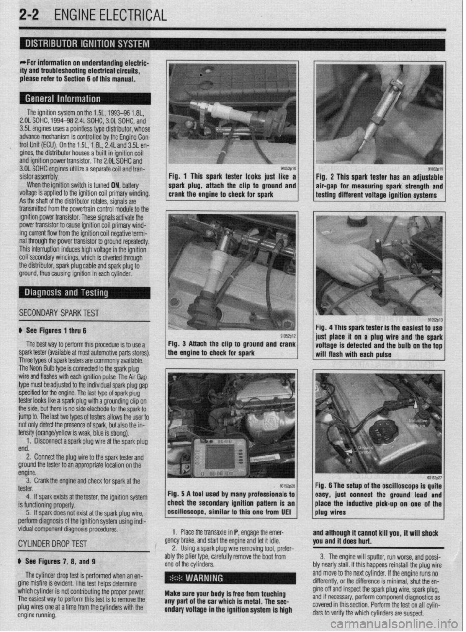
9105zp11 Fig. 1 This spark tester looks iust like a
Fiu. 2 This spark tester has an adjustable
spark plug, attach the clip to ground and air-gap for measuring spark strength and
crank the engine to check for spark testing different voltage ignition systems
.
ignition power trar rsistor. These signals activate the
power transistor to cause ignition coil primary wind-
ing current flow from the ignition coil negative termi-
nal through the power transistor to ground repeatedly.
This interruption induces high voltage in the ignition
coil secondarv windinas, which is diverted throuah
the distributor, spark plug cable and spark plug 6
ground, thus causing ignition in each cylinder.
I
SECONDARYSPARKTEST l;h.4-
! ,L ".~
'$ >,%
If See Figures 1 thru 6
91rJszp12 Fig. 4 This spark tester is the easiest to use
iust alace it on a plug wire and the spark
The best way to perform this procedure is to use a Fig. 3 Attach the clip to ground and crank
spark tester (available at most automotive parts stores). the engine to check for spark
I I voltage is detected and the bulb on the tof
-. will flash with each pulse
I nree types ot spark testers are commonly available.
The Neon Bulb type is connected to the spark plug
wire and flashes with each ignition pulse. The Air Gap
type must be adjusted to the individual spark plug gap
specified for the engine. The last type of spark plug
tester looks like a spark plug with a grounding clip on
the side, but there is no side electrode for the spark to
jump to. The last two types of testers allows the user to
not only detect the presence of spark, but also the in-
tensity (orange/yellow is weak, blue is strong).
1. Disconnect a spark plug wire at the spark plug
end.
2. Connect the plug wire to the spark tester and
ground the tester to an appropriate location on the
engine.
3. Crank the engine and check for spark at the
tester.
4. If spark exists at the tester, the ignition system
is functioning properly.
5. If spark does not exist at the spark plug wire,
perform diagnosis of the ignition system using indi-
vidual component diagnosis procedures,
CYLINDER DROPTEST
p See Figures 7, 8, and 9
The cylinder drop test is performed when an en-
gine misfire is evident. This test helps determine
which cylinder is not contributing the proper power.
The easiest way to perform this test is to remove the
plug wires one at a time from the cylinders with the
engine running. 1. Place the transaxle in P, engage the emer-
gency brake, and start the engine and let it idle.
2. Using a spark plug wire removing tool, prefer-
ably the plier type, carefully remove the boot from
one of the cylinders.
i ’
Make sure your body is free from touching
any part of the car which is metal. The sec-
ondary voltage in the ignition system is high and although it cannot kill you, it will shock
you and it does hurt.
3. The engine will sputter, run worse, and possi-
bly nearly stall. If this happens reinstall the plug wire
and move to the next cylinder. If the engine runs no
differently, or the difference is minimal, shut the en-
gine off and inspect the spark plug wire, spark plug,
and if necessary, perform component diagnostics as
covered in this section. Perform the test on all cylin-
ders to verify the which cylinders are suspect.
Page 52 of 408
ENGlNEELECTRliAL 2-5
Fig. 19 Adjusting the distributor-1.5L en-
gine shown, others similar
4. Install the hold-down nut.
5. Attach the distributor harness connectors.
6. Install the distributor cap.
7. Connect the negative battery cable.
8. Adjust the ignition timing and tighten the hold-
down nut to 8 ft. Ibs. (11 Nm).
For procedures on the position sensors, please re-
fer to Section 4 in this manual.
The ignition system found on the 1.6L, 1997-60
1.8L, 2.OL DOHC, 1999-00 2.4L SOHC, 2.4L DOHC,
and 3.OL DOHC engines is a distributorless type.
The advance of this system, like the distributor type
ignition, is controlled by the Engine Control Unit
(ECU) or Powertrain Control Module (PCM). The
distributorless ignition system contains a crank an-
gle/position sensor which detects the crank angle or
position to each cylinder and converts this data into
pulse signals. These signals are sent to the
ECLVPCM, which calculates the engine rpm and
regulates the fuel injection and ignition timing ac-
cordingly. The system also contains a top dead cen-
ter sensor which detects the top dead center position
of each cylinder and converts this data into pulse
signals. These signals are then sent to the
ECU/PCM, which calculates the sequence of fuel in-
jection and engine rpm.
When the ignition switch is turned ON, battery
voltage is applied to the ignition coil primary wind-
ing. As the crank angle sensor shaft rotates, ignition
signals are transmitted from the multi port injection
control unit to the power transistor. These signals
activate the power transistor to cause ignition coil
primary winding current to flow from the ignition
coil negative terminal through the power transistor
to ground or be interrupted, repeatedly. This action
induces high voltage in the secondary winding of
the ignition coil. From the ignitron coil, the sec-
ondary winding current produced flows through the
spark plug to ground, thus causing ignition in each
cylinder.
Refer to Diagnosis and Testing under Distributor
Ignition in this section,
There are no adjustments to the distributorless ig-
nition system other than the ignition timing adjust-
ment. Refer to section 1 for ignition timing adjust-
ment.
TESTING
1.6L and 1990 2.OL DOHC Engines
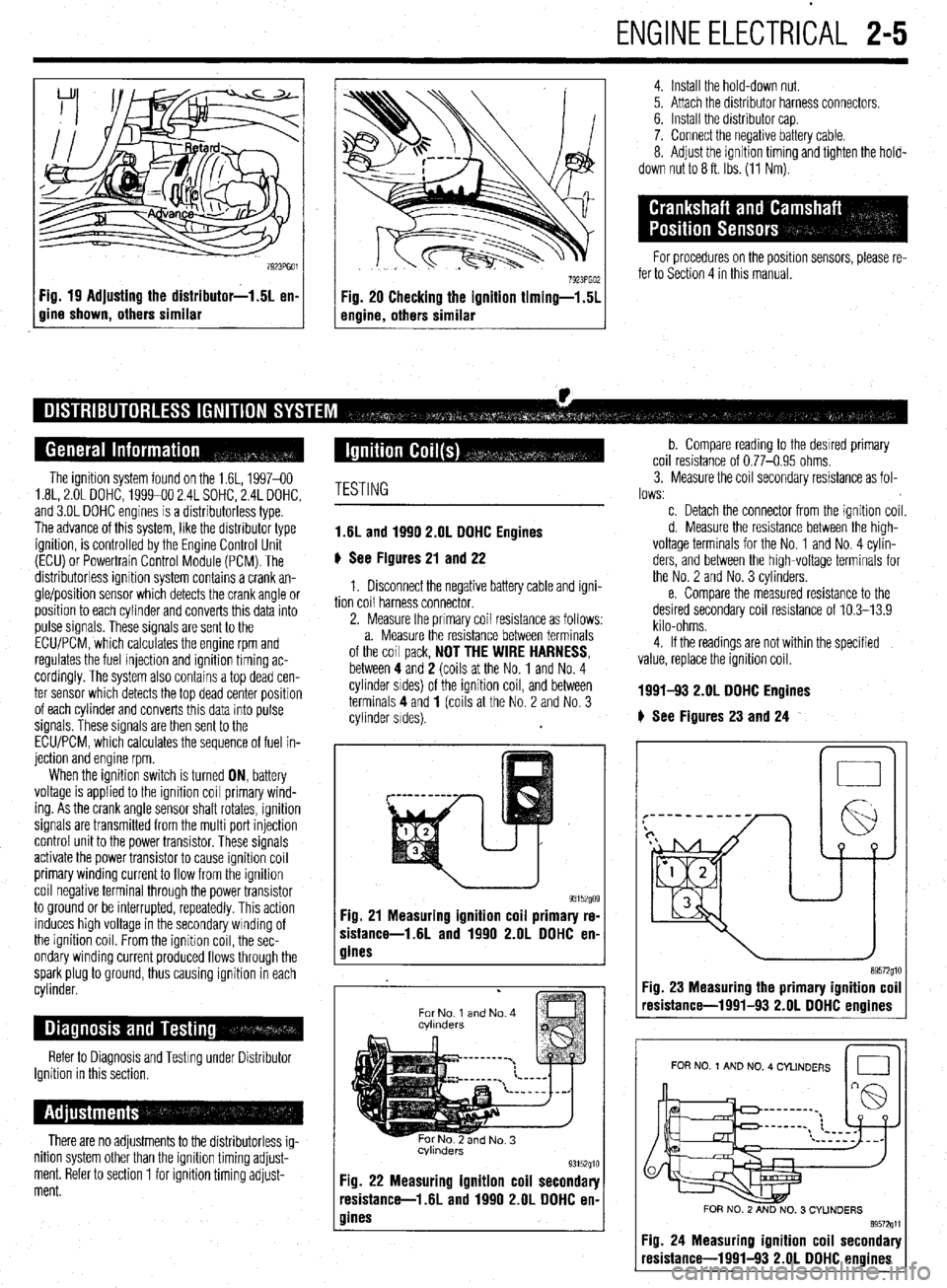
6 See Figures 21 and 22
1. Disconnect the negative battery cable and igni-
tion coil harness connector.
2. Measure the primary coil resistance as follows:
a. Measure the resistance between terminals
of the coil pack,
NOT THE WIRE HARNESS, between 4 and 2 (coils at the No. 1 and No. 4
cylinder srdes) of the ignition coil, and between
terminals 4 and
1 (coils at the No. 2 and No. 3
cylinder sides).
93152go9 Fig. 21 Measuring ignition coil primary re-
sistance-1.6L and 1990 2.OL DDHC en-
gines
.
For No 1 and No. 4
cvlmders
Fig. 22 Measuring ignition coil secondary
resistance-l .6L and 1990 2.OL DOHC en-
gines
b. Compare reading to the desrred primary
coil resistance of 0.77-0.95 ohms.
3. Measure the coil secondary resistance as fol-
lows:
c. Detach the connector from the ignition coil.
d. Measure the resistance between the high-
voltage terminals for the No. 1 and No. 4 cylin-
ders, and between the high-voltage terminals for
the No. 2 and No. 3 cylinders.
e. Compare the measured resistance to the
desired secondary coil resistance of 10.3-13.9
kilo-ohms.
4. If the readings are not within the specified
value, replace the ignition coil.
1991-!I3 2.OL DDHC Engines
# See Figures 23 and 24
n 0
Fig. 23 Measuring the primary ignition coil
resistance-1991-93 2.OL DOHC enoines
I I
FOR NO 1 AND NO. 4 CYLINDERS
Id
FOR NO. 2 AND NO. 3 CYUNDERS
89572611
Fig. 24 Measuring ignition coil secondary
resistance-1991-93 2.OL DOHC engines
Page 59 of 408
.
2-12 ENGINEELECTRICAL
*This section describes the operating prina
ciples of sending units, warning lights and
gauges. Sensors which provide information
to the Enafne Control Unit (ECU) or Electronic
or Power&in Control Module (FCM/PCM) are
covered in Section 4 of this manual.
Instrument panels contain a number of indicating
devices (gauges and warning lights). These devices
are composed of two separate components. One is
the sending unit, mounted on the engine or other re-
mote part of the vehicle, and the other is the actual
gauge or light in the instrument panel.
Several types of sending units exist, however most
can be characterized as being either a pressure type
or a resistance type. Pressure type sending units
convert liquid pressure into an electrical signal which
is sent to the gauge. Resistance type sending units
are most often used to measure temperature and use
variable resistance to control the current flow back to
the indicatinq device. Both types of sendinq units are
connected inseries by a wimto the batteryithiough
the ignition switch). When the ignition is turned ON,
current flows from the battery through the indicating
device and on to the sending unit.
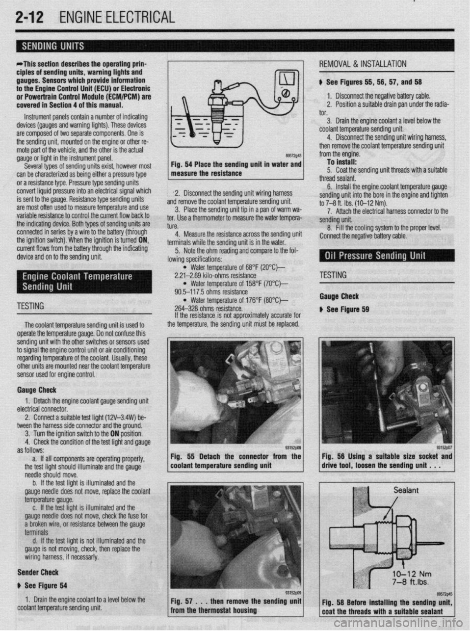
89572$43 Fig. 54 Place the sending unit in water and
measure the resistance
2. Disconnect the sending unit wiring harness
and remove the coolant temperature sending unit.
3. Place the sending unit tip in a pan of warm wa-
ter. Use a thermometer to measure the water tempera-
tl KP
L”,“.
4. Measure the resistance across the sending uni
terminals while the sending unit is in the water.
5. Note the ohm reading and compare to the fol-
lowing specifications: i, 56, 57, and 56
1. Disconnect the negative battery cable.
2. Position a suitable drain pan under the radia-
tor.
3. Drain the engine coolant a level below the
coolant temperature sending unit.
4. Disconnect the sending unit wiring harness,
then remove the coolant temperature sending unit
from the engine.
To install:
5. Coat the sending unit threads with a suitable
thread sealant.
6. Install the engine coolant temperature gauge
sending unit into the bore in the engine and tighten
to 7-8 ft. Ibs. (10-12 Nm).
7. Attach the electrical harness connector to the
sendina unit.
8. fill the cooling system to the proper level.
:onnect the negative battery cable.
l Water temperature of 68°F (2O”C)-
2.21-2.69 kilo-ohms resistance
l Water temperature of 158°F (7O’Ck
90.5-117.5 ohms resistance
TESTING l Water temperature of 176°F (8O”C)-
264-328 ohms resistance.
The coolant temperature sendina unit is used to
operate the temperature gauge. Donot confuse this
sending unit with the other switches or sensors used
to signal the engine control unit or air conditioning
regarding temperature of the coolant. Usually, these
other units are mounted near the coolant temoerature
sensor used for engine control. If the resistance is not approximately accurate for
the temperature, the sending unit must be replaced.
Gauge Check
1. Detach the engine coolant gauge sending unit
electrical connector.
2. Connect a suitable test liaht (12V-3.4W) be-
tween the harness side connector and the around.
I
3. Turn the ignition switch to the ON position.
4. Check the condition of the test light and gauge
as follows:
a. If all components are operating properly,
the test light should illuminate and the gauge
needle should move.
b. If the test light is illuminated and the
gauge needle does not move, replace the coolant
temperature gauge.
c. If the test light is illuminated and the
gauge needle does not move, check the fuse for
a broken wire, or resistance between the gauge
terminals
d. If the test light is not illuminated and the
gauge is not moving, check, then replace the
wiring harness, if necessar!y.
Sender Check
p See Figure 64
1. Drain the engine coolant to a level below the
coolant temperature sending unit Fig. 55 Detach the connector from the
coolant temperature sending unit
'ESTING
tauga Check
See Ftgure 69
Page 152 of 408
DRIVEABILITYAND EMISSIOP JSCONTRiLS 4-9
3. Label and disconnect the H02S from the en-
gine control wiring harness.
*Lubricate the sensor with penetrating oil
prior to removal.
4. Remove the sensor using an oxygen sensor
I To install: - -v- -- ---- ..----. ----...= -..- r... *-
5. Install the sensor in the mounting boss and
hl-li)r\,,.l 0 ,.l.-.f.l, .T‘fi.LI wrench or another suitable tool.
tighten to 27-33 ft. Ibs. (37-45 Nm).
6. Connect the engine control wiring harness to 1 Fia. 43 IAC mntnr tnfitinn and nin Incations 1
KtMUVHL i% IN3 I ALLA I IUN
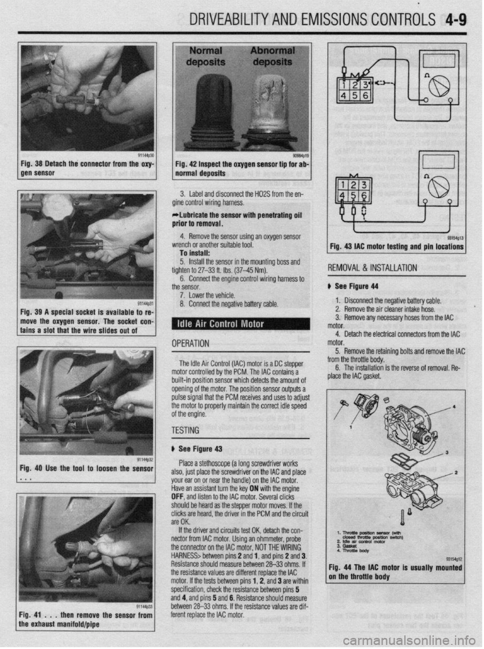
See Fiaurr! d4
1. Disconnect the negative battery cable.
2. Remove the air cleaner intake hose.
move the oxygen sensor. The socket con- 3. Remove any necessary hoses from the IAC
OPERATION
The Idle Air Control (IAC) motor is a DC stepper
motor controlled by the PCM. The IAC contains a
built-in position sensor which detects the amount of
opening of the motor. The position sensor outputs a
pulse signal that the PCM receives and uses to adjust
the motor to properly maintain the correct idle speed
of the engine. motor.
5. Remove the retainino bolts and remove the IAC
y -_.._ -..- ._... -._ . .._ ._ from the throttle body. C The inc.hllrrti~n a 11o IIIJL(IIIoLIuII is the reverse of removal. Re-
plaie the IAC gasket.
TESTING
I
ti See Figure 43
Place a stethoscope (a long screwdriver works
also, just place the screwdriver on the IAC and place
your ear on or near the handle) on the IAC motor.
Have an assistant turn the key ON with the engine
OFF, and listen to the IAC motor. Several clicks
should be heard as the steooer motor moves. If the
clicks are heard, the driver in the PCM and the circuit
are OK.
If the driver and circuits test OK, detach the con-
nectar from IAC motor. Using an ohmmeter, probe ‘. l-!AEz?rn~ -w
2 Idle an conh0l motor nswltch)
the connector on the IAC motor, NOT THE WIRING
HARNESS> between pins 2 and 1, and pins 2 and 3.
Resistance should measure between 26-33 ohms. If
the resistance values are different replace the IAC tor is usually mounted
motor. If the tests between pins 1,2, and 3 are within
specification, check the resistance between pins 5
and 4, and pins 5 and 6. Resistance should measure
between 26-33 ohms. If the resistance values are dif-
then remove the sensor from ferent replace the IAC motor.
Page 153 of 408
4-10 DRIVEABILITYAND EMISSIONS CONTROLS
I
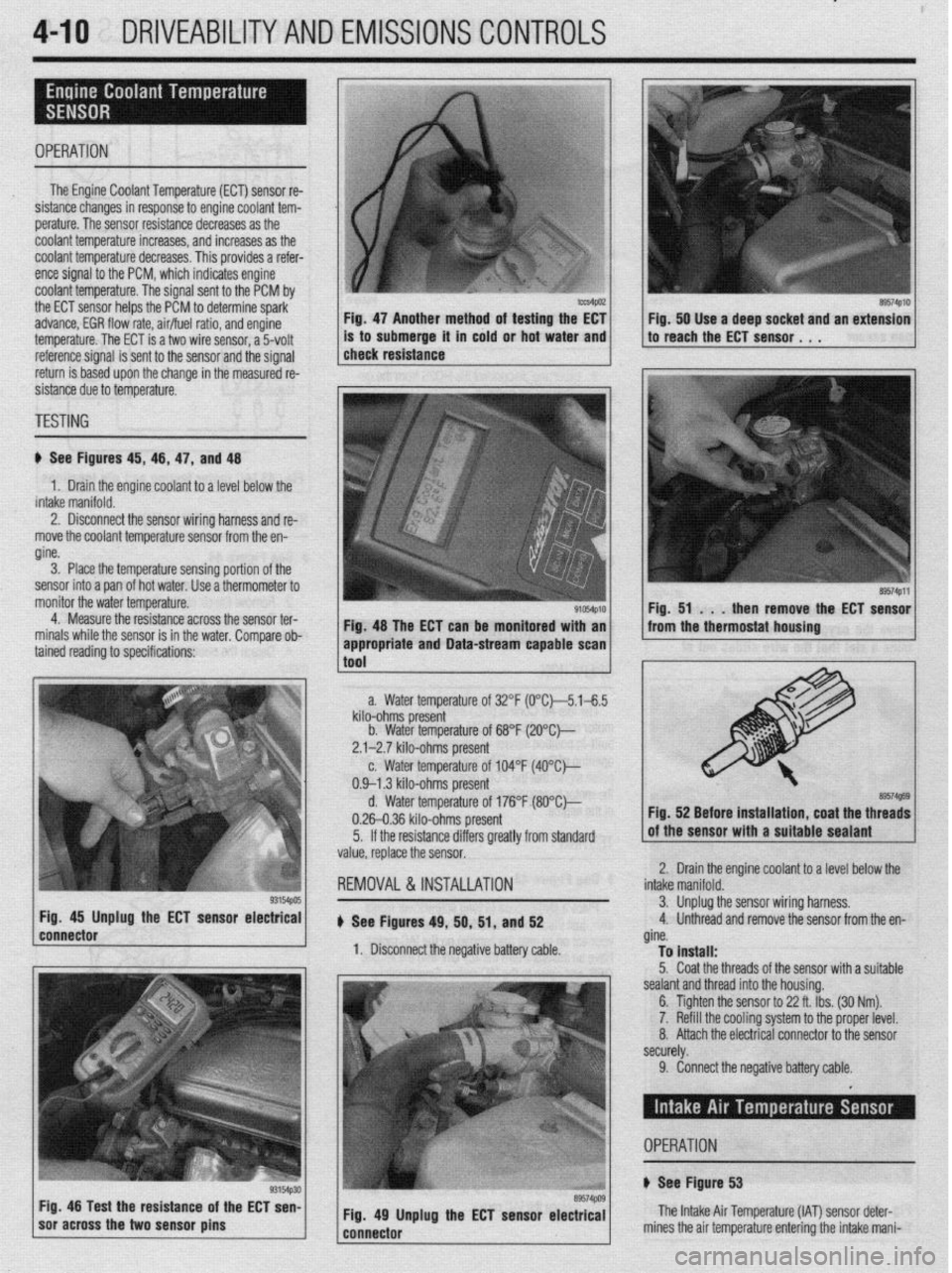
OPERATION
The Engine Coolant Temperature (ECT) sensor re-
sistance changes in response to engine coolant tem-
perature. The sensor resistance decreases as the
coolant temperature increases, and increases as the
coolant temperature decreases. This provides a refer-
ence signal to the PCM, which indicates engine
coolant temperature. The signal sent to the PCM by
the ECT sensor helps the PCM to determine spark-
advance, EGR flow rate, air/fuel ratio, and engine
temperature. The ECT is a two wire sensor, a 5volt
3. Place the temperature sensing portion of the
sensor into a pan of hot water. Use a thermometer to
monitor the water temperature.
4. Measure the resistance across the sensor ter-
minals while the sensor is in the water. Comoare ob- Fig. 47 Another method of testing the EC1 Fig. 50 Use a deep socket and an extension
is to submerge it in cold or hot water and to reach the ECT sensor. 1 ,
reference signal is sent to the sensor and the signal
return is based upon the change in the measured re-
sistance due to temperature. 1 check resistance
TESTING
ti See Figures 45, 46, 47, and 48
1. Drain the engine coolant to a level below the
intake manifold.
2. Disconnect the sensor wiring harness and re-
move the coolant temperature sensor from the en-
gine.
Fig. 48 The ECT can be monitored with an
tained reading to specifications: ’
93154pos Fig. 45 Unplug the ECT sensor electrical
connector
1 soracross the two sensor pins g3154p30 Fig 48 Test the resistance of the ECT sen-
89574PlO
89574Pll
Fig. 51 . . .
then remove the ECT sensor
from the thermostat housing
a. Water temperature of 32°F (0°C~5.1-6.5
kilo-ohms present
b. Water temperature of 68°F (2O”C)--
2.1-2.7 kilo-ohms present
c. Water temperature of 104°F (4O”C)---
0.9-l .3 kilo-ohms present
d. Water temperature of 176°F (8O”Ck,
0.26-0.36 kilo-ohms present
5. If the resistance differs greatly from standard
value, replace the sensor.
REMOVAL &INSTALLATION
u See Figures 49, 50, 51, and 52
1. Disconnect the negative battery cable. Fig. 52 Before installation, coat the threads
Iolant to a level below the 2. Drain the engine c(
intake manifold.
3. Unplug1 the sensor wiring harness,
4. Unthreac
d and remove the sensor from the en-
gine.
To install:
5. Coat the threads of the sensor with a suitable
sealant and thread into the housing.
6. Tighten the sensor to 22 ft. Ibs. (30 Nm).
7. Refill the cooling system to the proper level.
8. Attach the electrical connector to the sensor
securely. appropriate and Data-stream capable scan 1
1
tnnl
9. Connect the negative battery cable.
Fig. 49 Unplug the ECT sensor electrical
---..^-s-- The Intake Air Temperature (IAT) sensor det
mines the air temnerature enterinn the! intake n er-
- ._ r_ -.-._ _. ._. J . _ ..-. ._
iani- OPERATION
+ See Figure 53
Page 154 of 408
DRIVEABILITYAND EMISSIONS CONTROLi 4-11
fold. Resistance changes in response to the ambient
air temperature. The sensor has a negative tempera-
ture coefficient. As the temperature of the sensor
rises the resistance across the sensor decreases. Thil
provides a signal to the PCM indicating the tempera-
ture of the incoming air charge. This sensor helps the
PCM to determine spark timing and air/fuel ratio. In-
formation from this sensor is added to the pressure
sensor information to calculate the air mass being
sent to the cylinders. The IAT receives a 5-volt refer-
ence signal and the signal return is based upon the
change in the measured resistance due to tempera-
ture.
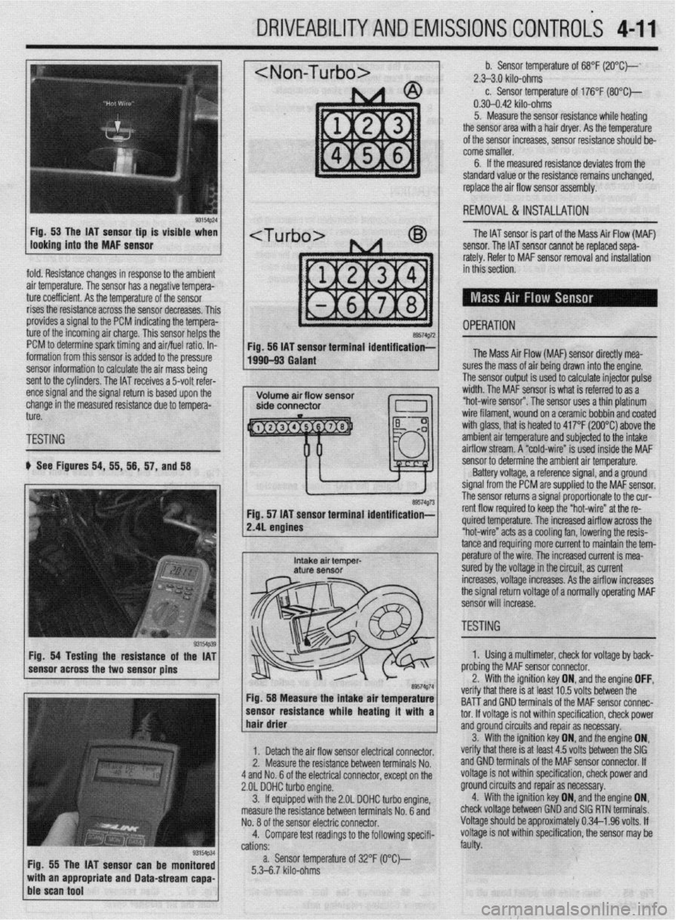
TESTING
b See Figures 54, 55, 56, 57, and 58
Fig. 54 Testing the resistance of the IAT
sensor across the two sensor pins
Fig. 55 The IAT sensor can be monitored
with an appropriate and Data-stream capa-
ble scan tool
~1 b. Sensor temperature of 68°F (2O”C)--‘ 2.>3.0 kilo-ohms c. Sensor temperature of 176°F (SO*C)-
0.30-0.42 kilo-ohms
5. Measure the sensor resistance while heating
the sensor area with a hair dryer. As the temperature
of the sensor increases, sensor resistance should be-
come smaller.
6. If the measured resistance deviates from the
standard value or the resistance remains unchanged,
replace the air flow sensor assembly.
1 REMOVAL&INSTALLATION
The IAT sensor is part of the Mass Air Flow (MAF)
sensor. The IAT sensor cannot be replaced sepa-
rately. Refer to MAF sensor removal and installation
in this section.
- OPERATION a9574g72 Fig. 56 IAT sensor terminal identification;-
1990-93 Galant The Mass Air Flow (MAF) sensor directly mea-
lres the mass of air being drawn into the engine.
I ?he sensor output is used to calculate injector pulse
width. The MAF sensor is what is referred to as a
“hot-wire sensor”. The sensor uses a thin platinum
wire filament, wound on a ceramic bobbin and coated
with glass, that is heated to 417°F (200°C) above the
amh+en+ nir +PmnPrfijre and subiected to the intake
..I._ ~ ..-.. .“..‘r-,u.. ai mow stream. A “cold-wire” is used inside the MAF
sensor resuirance wnoe nearmg ir wnn a 1
hair drier ‘hat melt: IS al I~“< ,“.., lvllQ UtiLnbtill ,,,=
tnd GND terminals of the MAF sensor connec-
tor. If voltaae is not within specification, check power
1. Detach the air flow sensor electrical connector.
2. Measure the resistance between terminals No.
4 and No. 6 of the electrical connector, except on the
2.OL DOHC turbo engine.
3. ff equipped with the 2.OL DOHC turbo engine,
measure the resistance between terminals No. 6 and
No. 8 of the sensor electric connector.
4. Compare test readings to the following specifi-
cations:
a. Sensor temperature of 32°F (O“C)--
5.3-6.7 kilo-ohms and groundcircuits and repair as necessary.
verify that there is at least 4.5 volts between the SIG 3. With the ignition key ON, and,the engine ON,
and GND terminals of the MAF sensor connector. If
voltage is not within specification, check power and
ground circuits and repair as necessary.
4. With the ignition key ON, and the engine ON,
check voltage between GND and SIG RTN terminals.
Voltage should be approximately 0.34-l .96 volts. If
voltage is not within specification, the sensor may be
faulty.
/ sensor to determine the ambient air temperature.
Battery voltage, a reference signal, and a ground
signal from the PCM are supplied to the MAF sensor.
rho ~pn**r rp+++rns a signal proportionate to the cur-
re. The increased airflow across the
s a cooling fan, lowering the resis-
mo more current to maintain the tem- tance and requir
e^-‘.._^ ^I LL^
I
Intake air temper- pe~a+ure UI me wire. The increased current is mea- aturf sensor sured by the voltage in the circuit, as current
increases, voltage increases. As the airflow increases
the signal return voltage of a normally operating MAF
sensor will increase.
, ~~1 TESTING - II ire” at the re-
89574g74 Fig. 58 Measure the intake air temperature
-----_ ---1-a---- L..- L--1. . . .*a 1. Using a multimeter, check for voltage by back-
nrr\hinn +hn MAF sensor connector.
the ignition key ON, and the engine OFF, .^-^ :- -’ ‘.txt In E; \mltr hahrman tha veriry t
BAT-T i
Page 156 of 408
DRIVEABILITYAND EMISSIONS CONTROiS 4-13
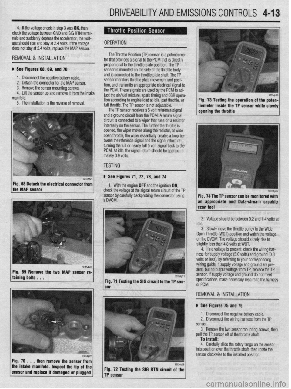
4. If the voltaoe check in sbo 3 was OK. then
check the voltage-between GND’and SIG RTN termi-
nals and suddenly depress the accelerator, the volt-
age should rise and stay at 2.4 volts. If the voltage
OPERATION does not stay at 2.4 volts, replace the MAP sensor.
REMOVAL&INSTALLATION '
ti See Figures 68, 69, and 70
1. Disconnect the negative bat lery cable.
2. Detach the connector for thl e MAP sensor.
3. Remove the sensor mountir ig screws.
4. Lift the sensor up and remove it from the intake
manifold. The Throttle Posii
ti-* \*. Inn ITPl smsnr is 8 Dotentiome- , WI...,". *., . ter that provides a si gnal to the PCM that is directly
proportion: il to the throttle plate position. The TP
sensor is rr iounted on the side of the throttle body
and is connected to the throttle plate shaft. The TP
sensor monitors throttle plate movement and posi-
tion, and transmits an appropriate electrical signal to
the PCM. These signals grp IIQX-I hv rho PCM to ad-
just the air/flnI mivtlI “-- ------li
5. The installation is the reverse of removal. WI I dLfUl U full throttle The TP c
UyI ,,,,,,,:re, spark timing and EGR opera-
ng to engine load at idle, part throttle, or
The TP sensor is not adjustable.
..-
lensor receives a 5 volt reference signal
and a ground circuit from the PCM. A return signal
circuit is connected to a wiper that runs on a resistor
internally on the sensnr ThP fmth@r rho throttle is
opined the winnr mr oP -*lY”, .I,” ..,y’V, 111 Jves along the resistor, at wide
en throttle, the wiper essentially creates a loop be-
tween the reference signal and the signal return re-
turning the full or nearly full 5 volt signal back to the
PCM. At idle, the signal return should be approxi-
rnz
rtely 0.9 volts.
TF
iSTING
) See Figures 71 ,72, 73, and 74
1. With the engine OFF and the ignition ON,
check the voltage at the signal return circuit of the TP
sensor bv carefullv backorobina the connector using
aDVOM: . ” Fig. 68 Detach the electrical connector from
the MAP sensor
taining bolts . . . WMp,l
Fig. 71 Testing the SIG circuit to the TP sen-
then remove the sensor from
the intake manifold. Inspect the tip of the
sensor and replace if damaged or plugged Fig. 72 Testing the SIG RTN circuit of the
TP sensor
sm4p10 I Fig. 73 Testing the operation of the poten- 1
tiometer inside the TP sensor while slowly 1
opening the throttle
Fig. 74 The TP sensor can be monitored with
an appropriate and Data-stream capable
2. Voltage should be between 0.2 and 1.4 volts at
idle.
3. Slowlv move the throttle oullev to the Wide
Open Throttle (WOT) position and watch the voltage
on the DVOM. The voltage should slowly rise to
slightly less than 4.8 volts at WOT.
4. If no voltage is present, check the wiring har-
ness for supply voltage (5.0 volts) and ground (0.3
volts or less), by referring to your corresponding
wiring guide. If supply voltage and ground are pre-
sent, but no output voltage from TP, replace the TP
sensor. If supply voltage and ground do not meet
specifications, make necessarv reoairs to the harness
or PCM.
,
REMOVAL&INSTALLATION
# See Figures 75 and 76
1. Disconnect the negative battery cable.
2. Disconnect the wiring harness from the TP
sensor.
3. Remove the two sensor mounting screws, then
pull the TP sensor off of the throttle shaft.
To install:
4. Carefully slide the rotary tangs on the sensor
into position over the throttle shaft. then rotate the
sensor clockwise to the installed position.
Page 169 of 408
4-26 DRIVEABILITYAND EMISSIONS CONTROLS
The Powertrain Control Module (PCM) monitors
the signals of input and output sensors, some all the
time and others at certain times and processes each
signal. When the PCM notices that an irregularity has
continued for a specified time or longer from when
the irregular signal was initially monitored, the PCM
judges that a malfunction has occurred and will
memorize the malfunction code. The code is then
stored in the memory of the PCM and is accessible
through the data link (diagnostic connector) with the
use of an electronic scan tool or a voltmeter.
CHECK ENGINE/MALFUNCTION
INDICATOR LIGHT
Among the on-board diagnostic items, a check
engine/malfunction indicator light comes on to notify
the driver of a emission control component irregular-
ity. If the irregularity detected returns to normal or the
PCM judges that the component has returned to nor-
mal, the check engine/malfunction indicator light will
be turned off Moreover, if the ignition is turned OFF
and then the engine is restarted, the check
engine/malfunction indicator light will not be turned
on unttl a malfunction is detected.
The check engine/malfunction indicator light will
come on immediately after the ignition switch is
turned ON. The light should stay lit for 5 seconds
and then will go off. This Indicates that the check en-
gine/malfunction indicator lamp is operating nor-
mally. This does not signify a problem with the sys-
tem.
*The check engine/malfunction indicator
lamp will come on when the terminal for the
ignition timing adjustment is shorted to
ground. Therefore, it is not abnormal that the
light comes on even when the terminal for ig-
nition timing is shorted at time of ignition
timing adjustment.
To test the light, perform the following:
1. Turn the ignition switch ON. Inspect the check
engine/malfunction indicator lamp for Illumination.
2. The light should be lit for 5 seconds and then
should go out.
3. If the lamp does not illuminate, check for open
circuit In the harness, blown fuse or blown bulb.
SERVICE PRECAUTIONS
l Before attachrng or detaching the PCM harness
connectors, make sure the ignition switch is OFF and
the negative battery cable is disconnected to avoid
the possibility of damage to the PCM.
l When performing PCM input/output signal di-
agnosis, remove the pin terminal retainer from the
connectors to make it easier to insert tester probes
into the connector.
l When attaching or detaching pin connectors ,
from the PCM, take care not to bend or break any pin
terminals. Check that there are no bends or breaks on
PCM pin terminals before attempting any connec-
tions.
l Before replacing any PCM, perform the PCM
input/output signal diagnosis to make sure the PCM
is functioning properly.
l When measuring supply voltage of PCM-con-
trolled components with a circuit tester, separate 1
tester probe from another. If the 2 tester probes acci-
dentally make contact with each other during mea-
surement, a short circuit WIII result and damage the
PCM.
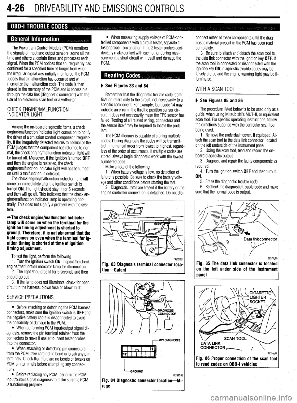
# See Figures 83
and 84
Remember that the diagnostic trouble code identi-
fication refers only to the circuit, not necessarily to a
specific component. For example, fault code 14 may
indicate an error in the throttle position sensor cir-
cuit; it does not necessarily mean the TPS sensor has
failed Testing of all related wiring, connectors and
the sensor itself may be required to locate the prob-
lem.
The PCM memory is capable of storing multiple
codes. During diagnosis the codes will be transmlt-
ted in numerical order from lowest to highest, regard-
less of the order of occurrence. If multiple codes are
stored, always begin diagnostic work with the lowest
numbered code
Make a note of the following:
1. When battery voltage IS low, no detection of
failure is possible. Be sure to check the battery volt-
age and other conditions before starting the test.
2. Diagnostic items are erased if the battery or the
engine controller connection is detached. Do not dis- connect either of these components until the diag-
nostic material present in the PCM has been read
completely.
3. Be sure to attach and detach the scan tool to
the data link connector with the ignition key OFF. If
the scan tool in connected or disconnected with the
ignition key ON, diagnostic trouble codes may be
falsely stored and the engine warning light may be il-
luminated. WITHASCANTOOL
) See Figures 85 and 86
The procedure listed below is to be used only as a
guide, when using Mitsubishi’s MUT-II, or equivalent
scan tool. For specific operating instructions, follow
the directions supplied with the particular scan tool
bemg used.
1. Remove the underdash cover, if equipped. At-
tach the scan tool to the data link connector, located
on the left underside of the instrument panel.
2. Using the scan tool, read and record the on-
board diagnostic output.
3. Diagnose and repair the faulty components as
required
4. Turn the ignition switch OFF and then turn it
ON.
5. Erase the diagnostic trouble code.
6 Recheck the diaanostic trouble code and make
sure that the normal &de is output.
79232G37 89574g98 Fig. 83 Diagnosis terminal connector loca-
tion-Galant Fig. 85 The data link connector is located
on the left under side of the instrumeni
panel
,--MU DL4GNDSl.S
LGRDIJND
79232638
Fig. 84 Diagnostic connector Iocation-Mi-
‘age
ata link connector
89574994 Fig. 86 Proper connection of the scan tool to read codes on OBD-I vehicles
Page 170 of 408
DRIVEABILITYAND EMISSIONS CONTROLS 4-27
WITHOUTASCANTOOL
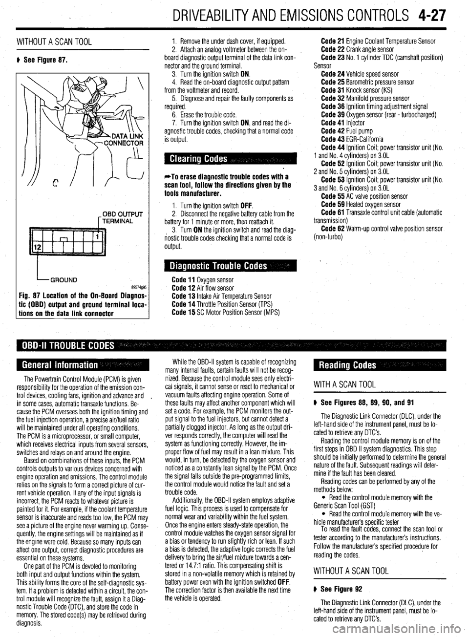
8 See Figure 87. 1. Remove the under dash cover, if equipped.
2. Attach an analoa voltmeter between the on-
board diagnostic outpit terminal of the data link con-
nector and the ground terminal
3. Turn the ignition switch ON.
4. Read the on-board diagnostic output pattern
from the voltmeter and record.
5. Diagnose and repair the faulty components as
required.
OBD OUTPUT
[TERMINAL
tic (OBO) output and ground terminal loca-
tions on the data link connector
6. Erase the trouble code.
7. Turn the ignition swatch ON, and read the di-
agnostic trouble codes, checking that a normal code
is output.
*To erase diagnostic trouble codes with a
scan tool, follow the directions given by the
tools manufacturer.
1. Turn the ignition switch OFF. 2. Disconnect the negative battery cable from the
battery for 1 minute or more, then reattach it.
3. Turn ON the ignition switch and read the diag-
nostic trouble codes checking that a normal code is
output.
Code 11 Oxygen sensor Code 12 Air flow sensor Code 13 Intake Air Temperature Sensor Code 14 Throttle Position Sensor (TPS) Code 15 SC Motor Position Sensor (MPS)
Code 21 Engine Coolant Temperature Sensor Code 22 Crank angle sensor Code 23 No. 1 cylinder TDC (camshaft position)
Sensor
Code 24 Vehicle speed sensor Code 25 Barometric pressure sensor Code 31 Knock sensor (KS) Code 32 Manifold pressure sensor Code 36 Ignition timmg adjustment signal Code 39 Oxygen sensor (rear - turbocharged) Code 41 Injector Code 42 Fuel pump Code 43 EGR-California Code 44 Ignition Coil; power transistor unit (No.
1 and No. 4 cvlinders) on 3.OL
Code 62 ignition Coil; power transistor unit (No.
2 and No. 5 cvlinders) on 3.OL
Code 53 ignition Coil; power transistor unit (No.
3 and No. 6 cylinders) on 3.OL
Code 55 AC valve position sensor Code 59 Heated oxygen sensor Code 61 Transaxle control unit cable (automatic
transmission)
Code 62 Warm-up control valve position sensor
(non-turbo)
The Powertrain Control Module (PCM) is given
responsibrlity for the operation of the emission con-
trol devices, cooling fans, ignition and advance and
in some cases, automatic transaxle functions. Be-
cause the PCM oversees both the ignition timing and
the fuel injection operation, a precise air/fuel ratio
will be maintained under all operating conditions,
The PCM is a microprocessor, or small computer,
which receives electrical inputs from several sensors,
switches and relays on and around the engine.
Based on combinations of these inputs, the PCM
controls outputs to various devices concerned with
engine operation and emissions. The control module
relies on the signals to form a correct picture of cur-
rent vehicle operation. If any of the input signals is
incorrect, the PCM reacts to whatever picture is
painted for it. For example, if the coolant temperature
sensor is inaccurate and reads too low, the PCM may
see a picture of the engine never warming up. Conse-
quently, the engine settings will be maintained as if
the engine were cold. Because so many inputs can
affect one output, correct diagnostic procedures are
essential on these systems,
One part of the PCM is devoted to monitoring
both input and output functions within the system.
This ability forms the core of the self-diagnostic sys-
tem. If a problem is detected within a circuit, the con-
trol module will recognize the fault, assign it a Diag-
nostic Trouble Code (DTC), and store the code in
memory. The stored code(s) may be retrieved during
diagnosis. While the OBD-II system is capable of recognizing
many internal faults, certain faults WIII not be recog-
nized. Because the control module sees only electri-
cal signals, it cannot sense or react to mechanical or
vacuum faults affecting engine operation. Some of
these faults may affect another component which will
set a code. For example, the PCM monitors the out-
put signal to the fuel injectors, but cannot detect a
partially clogged injector. As long as the output dri-
ver responds correctly, the computer will read the
system as functioning correctly. However, the im-
proper flow of fuel may result in a lean mixture. This
would, in turn, be detected by the oxygen sensor and
noticed as a constantly lean signal by the PCM. Once
the signal falls outside the pre-programmed limits,
the control module would notice the fault and set a
trouble code.
Additionally, the OBD-II system employs adaptive
fuel logic. This process is used to compensate for
normal wear and variability within the fuel system.
Once the engine enters steady-state operation, the
control module watches the oxygen sensor signal for
a bias or tendency to run slightly rich or lean. If such
a bias is detected, the adaptive logic corrects the fuel
delivery to bring the air/fuel mixture towards a cen-
tered or 14.7:1 ratio. This compensating shift is
stored In a non-volatile memory which is retained by
battery power even with the ignition switched
OFF. The correction factor is then available the next time
the vehicle is operated.
WITHASCANTOOL
8 See Figures 88, 89, 90, and 91
The Diagnostic Link Connector (DLC), under the
left-hand side of the instrument panel, must be lo-
cated to retrieve any OTC’s
Reading the control module memory is on of the
first steps in OBD II system diagnostics. This step
should be initially performed to determine the general
nature of the fault. Subsequent readings will deter-
mine if the fault has been cleared.
Reading codes can be performed by any of the
methods below:
l Read the control module memory with the
Generic Scan Tool (GST)
l Read the control module memory with the ve-
hicle manufacturers specific tester
To read the fault codes, connect the scan tool or
tester according to the manufacturers instructions.
Follow the manufacturers specified procedure for
reading the codes.
WITHOUTASCANTOOL
8 See Figure 92
The Diagnostic Link Connector (DLC), under the
left-hand side of the instrument panel, must be lo-
cated to retrieve any DTC’s.
Page 190 of 408
FUELSYSTEM 513
l Always replace worn fuel fitting O-rings with
new. Do not substitute fuel hose or equivalent, where
I
The Multi-Point Injection (MPI) system is electroni-
rally controlled by the Engine Control Module (ECM),
based on data from various sensors. The ECM controls
the fuel flow, idle speed and ignition timing. fuel pipe is installed.
Fuel is supplied to the injectors by an electric in-
tank fuel pump and is distributed to the respective in-
jectors via the main fuel pipe. The fuel pressure ap-
plied to the injector is constant and higher than the
pressure in the intake manifold. The pressure is con-
trolled by the fuel pressure regulator. The excess fuel
is returned to the fuel tank through the fuel return pipe.
When an electric current flows in the injector, the
injector valve is fully opened to supply fuel. Since the
fuel pressure is constant, the amount of the fuel in-
jetted from the injector into the manifold is increased
or decreased in proportion to the time the electric
current flows. Based on ECU signals, the injectors in-
ject fuel to the cylinder manifold ports in firing order. Fuel injection systems remain under pres-
sure after the engine has been turned OFF.
Properly relieve fuel pressure before discon-
neeting any fuel lines. Failure to do so may
result in fire or personal injury.
1. Turn the ignition to the OFF position.
2. Loosen the fuel filler cap to release fuel tank
pressure.
I
The flow rate of the air drawn through the air
cleaner is measured by the air flow sensor. The air
enters the air intake plenum or manifold through the
throttle body. In the intake manifold, the air is mixed
with the fuel from the injectors and is drawn into the
cylinder, The air flow rate is controlled according to
the degree of the throttle valve and the servo motor
openings. The system is monitored through a num-
ber of sensors which feed information on engine con-
ditions and requirements to the ECM. The ECM cal-
culates the injection time and rate according to the
signals from the sensors,
Safety is the most important factor when perform-
ing not only fuel system maintenance but any type of
maintenance. Failure to conduct maintenance and re-
pairs in a safe manner may result in serious personal
injury or death. Maintenance and testing of the vehi-
cle’s fuel system components can be accomplished
safely and effectively by adhering to the following
rules and guidelines.
l To avoid the possibility of fire and personal in-
jury, always disconnect the negative battery cable un-
less the repair or test procedure requires that battery
voltage be applied.
l Always relieve the fuel system pressure prior to
disconnecting any fuel system component (injector,
fuel rail, pressure regulator, etc.), fitting or fuel line
connection. Exercise extreme caution whenever re- Observe all applicable safety precautions
when working around fuel. Whenever servic-
ing the fuel system, always work in a well
ventilated area. Do not allow fuel spray or va-
pors to come in contact with a spark or open
flame. Keep a dry chemical fire extinguisher
near the work area. Always keep fuel in a con-
tainer specifically designed for fuel storage;
also, always properly seal fuel containers to
avoid the possibility of fire or explosion.
3. For the Mirage, Diamante, and 1994-00
Galant, remove the rear seat cushion, then remove
the service cover and detach the fuel pump harness
connector.
4. For the 1990-93 FWD Galant, detach the fuel
pump harness connector located in the area of the
fuel tank. It may be necessary to raise the vehicle to
access the connector.
5. For the 1990-93 AWD Galant, remove the car-
pet from the trunk, locate the fuel tank wiring at the
pump access cover, then detach the wiring.
6. Start the vehicle and allow it to run until it
stalls from lack of fuel. Turn the key to the OFF posi-
tion.
7. Disconnect the negative battery cable, then at-
tach the fuel pump connector. Install the access .
cover, cushion or carpet as necessary.
8. Wrap shop towels around the fitting that is be-
ing disconnected to absorb residual fuel in the lines.
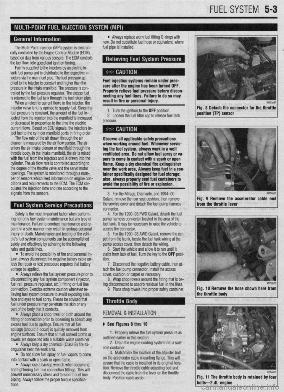
9. Place shop towels into proper safety container. Fig, 8 Detach the connector for the throttle
position (TP) sensor
93153ps5 Fig, 9 Remove the accelerator cable end
from the throttle lever
Fig. IO Remove the hose shown here from
lieving fuel system pressure to avoid exposing skin,
face and eyes to fuel spray. Please be advised that
fuel under pressure may penetrate the skin or any
part of the body that it contacts.
l Always place a shop towel or cloth around the
fitting or connection prior to loosening to absorb any
excess fuel due to spillage. Ensure that all fuel
spillage (should it occur) is quickly removed from
enginesurfaces. Ensure that all fuel soaked cloths or
towels are deposited into a suitable waste container.
l Always keep a dry chemical (Class B) fire ex-
tinguisher near the work area.
l Do not allow fuel spray or fuel vapors to come
into contact with a spark or open flame.
l Always use a backup wrench when loosening’
and tightening fuel line connection fittings. This will
prevent unnecessary stress and torsion to fuel line
piping. Always follow the proper torque specifica-
tions. REMOVAL &INSTALLATION
p See Figures 8 thru 18
1. Properly relieve the fuel system pressure as
outlined earlier in this section.
2. Drain the engine cooling system into a suit-
able container.
3. Matchmark the jocation of the adjuster bolt
on the accelerator cable mounting flange. This will
assure that the cable is installed in its original loca-
tion. Remove the throttle cable adjusting bolt and
disconnect the cable from the lever on the throttle
body. Position cable aside.