warning lights MITSUBISHI DIAMANTE 1900 Repair Manual
[x] Cancel search | Manufacturer: MITSUBISHI, Model Year: 1900, Model line: DIAMANTE, Model: MITSUBISHI DIAMANTE 1900Pages: 408, PDF Size: 71.03 MB
Page 59 of 408
.
2-12 ENGINEELECTRICAL
*This section describes the operating prina
ciples of sending units, warning lights and
gauges. Sensors which provide information
to the Enafne Control Unit (ECU) or Electronic
or Power&in Control Module (FCM/PCM) are
covered in Section 4 of this manual.
Instrument panels contain a number of indicating
devices (gauges and warning lights). These devices
are composed of two separate components. One is
the sending unit, mounted on the engine or other re-
mote part of the vehicle, and the other is the actual
gauge or light in the instrument panel.
Several types of sending units exist, however most
can be characterized as being either a pressure type
or a resistance type. Pressure type sending units
convert liquid pressure into an electrical signal which
is sent to the gauge. Resistance type sending units
are most often used to measure temperature and use
variable resistance to control the current flow back to
the indicatinq device. Both types of sendinq units are
connected inseries by a wimto the batteryithiough
the ignition switch). When the ignition is turned ON,
current flows from the battery through the indicating
device and on to the sending unit.
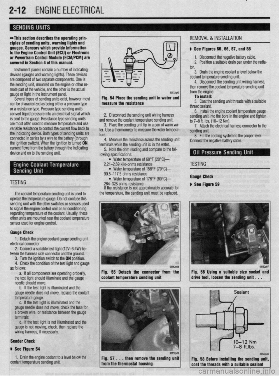
89572$43 Fig. 54 Place the sending unit in water and
measure the resistance
2. Disconnect the sending unit wiring harness
and remove the coolant temperature sending unit.
3. Place the sending unit tip in a pan of warm wa-
ter. Use a thermometer to measure the water tempera-
tl KP
L”,“.
4. Measure the resistance across the sending uni
terminals while the sending unit is in the water.
5. Note the ohm reading and compare to the fol-
lowing specifications: i, 56, 57, and 56
1. Disconnect the negative battery cable.
2. Position a suitable drain pan under the radia-
tor.
3. Drain the engine coolant a level below the
coolant temperature sending unit.
4. Disconnect the sending unit wiring harness,
then remove the coolant temperature sending unit
from the engine.
To install:
5. Coat the sending unit threads with a suitable
thread sealant.
6. Install the engine coolant temperature gauge
sending unit into the bore in the engine and tighten
to 7-8 ft. Ibs. (10-12 Nm).
7. Attach the electrical harness connector to the
sendina unit.
8. fill the cooling system to the proper level.
:onnect the negative battery cable.
l Water temperature of 68°F (2O”C)-
2.21-2.69 kilo-ohms resistance
l Water temperature of 158°F (7O’Ck
90.5-117.5 ohms resistance
TESTING l Water temperature of 176°F (8O”C)-
264-328 ohms resistance.
The coolant temperature sendina unit is used to
operate the temperature gauge. Donot confuse this
sending unit with the other switches or sensors used
to signal the engine control unit or air conditioning
regarding temperature of the coolant. Usually, these
other units are mounted near the coolant temoerature
sensor used for engine control. If the resistance is not approximately accurate for
the temperature, the sending unit must be replaced.
Gauge Check
1. Detach the engine coolant gauge sending unit
electrical connector.
2. Connect a suitable test liaht (12V-3.4W) be-
tween the harness side connector and the around.
I
3. Turn the ignition switch to the ON position.
4. Check the condition of the test light and gauge
as follows:
a. If all components are operating properly,
the test light should illuminate and the gauge
needle should move.
b. If the test light is illuminated and the
gauge needle does not move, replace the coolant
temperature gauge.
c. If the test light is illuminated and the
gauge needle does not move, check the fuse for
a broken wire, or resistance between the gauge
terminals
d. If the test light is not illuminated and the
gauge is not moving, check, then replace the
wiring harness, if necessar!y.
Sender Check
p See Figure 64
1. Drain the engine coolant to a level below the
coolant temperature sending unit Fig. 55 Detach the connector from the
coolant temperature sending unit
'ESTING
tauga Check
See Ftgure 69
Page 222 of 408
CHASSIS ELECTRICAL 6-19
1. Disconnect the negative battery cable.
are all built into 1 multi-function combination
2. Remove the instrument cluster, as outlined 1. Disconnect the negative battery cable.
earlier in this section. switch that is mounted on the steering col-
2. Using a small screwdriver or other suitable
umn. Refer to Section 8 for procedures re-
3. Remove the retaining screws for the instrument tool, carefully pry the retaining clips from either side
garding the combination switch.
cluster lens and cover assembly. Remove the cover of the switch trim plate.
3.
and lens. Carefully pull the switch and trim plate out of
,
4. Remove the retaining screws for the gauge or the instrument panel.
4. Detach the electrical connectors and remove
warning lamp to be replaced, then remove the gauge
the switch.
or warning lamp.
REMOVAL&INSTALLATION : 5. The installation is the reverse of removal.
To install:
5. Place the gauge or warning lamp into place
and tighten the retaining screws. 1. Disconnect the negative battery cable.
6. Install the instrument cluster lens and cover 2. Using a suitable prytool, disengage the switch
assembly. retaining tabs.
REMOVAL &INSTALLATION 7. Install the instrument cluster. 3. Gently pull the switch from the instrument
8. Connect the negative battery cable. panel.
4. Detach the electrical connector and remove the *On all models the headlights, turn signals,
switch. and on some models, the cruise control func-
5. The installation is the reverse of removal. tion are all built into 1 multi-function combi-
nation switch that is mounted on the steerinq
REMOVAL &INSTALLATION column. Refer to Section 8 for procedures 6
garding the combination switch.
*The headlights, turn signals, dimmer
switch, horn switch, windshield
REMOVAL &INSTALLATION
wiper/washer, intermittent wiper switch and *
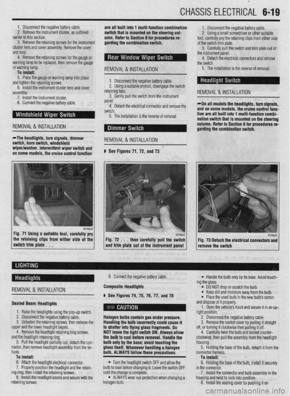
on some models, the cruise control function # See Figures 71, 72, and 73
the retaining clips from either side of the
switch trim plate . . . Fig. 72 . . . then carefully pull the switch
and trim plate out of the instrument panel Fig. 73 Detach the electrical connectors and
remove the switch
-
REMOVAL &INSTALLATION
Sealed Beam Headlights
1. Raise the headlights using the pop-up switch.
2. Disconnect the negative battery cable.
3. Unfasten the retaining screws, then remove the
upper and the lower headlight bezels.
4. Remove the headlight retaining ring screws,
and the headlight retaining ring.
5. Pull the headlight partially out, detach the con-
nectar, then remove headlight assembly from the ve-
hicle.
To install:
6. Attach the headlight electrical connector.
7. Properly position the headlight and the retain-
ing ring, then install the retaining screws.
8. Install the headlight bezels and secure with the
retaining screws. 9. Connect the negative battery cable.
Composite Headlights
6 See Figures 74, 75, 76, 77, anU78
Halogen bulbs contain gas under pressure.
Handling the
bulb incorrectly could cause it
to shatter into flying glass fragments. Do
NOT leave the light switch ON. Always allow
the bulb to cool before removal. Handle the
bulb only by the base; avoid touching the
glass itself. Whenever handling a halogen
bulb, ALWAYS follow these precautions:
l Turn the headlight switch OFF and allow the
bulb to cool before changing it. Leave the switch OFF
until the change is complete.
l ALWAYS wear eye protection when changing a
halogen bulb.
l Handle the bulb only by its base. Avoid touch-
ing the glass.
l DO NOT drop or scratch the bulb. l Keep dirt and moisture away from the bulb.
* Place the used bulb in the new bulb’s carton
and dispose of it properly.
1. Open the vehicle’s hood and secure it in an up-
right position.
2. Disconnect the negative battery cable.
3. Remove the socket cover by pulling it straight
off, or turning it clockwise then pulling it off.
4. Carefully twist the bulb and socket counter-
clockwise, then pull the assembly from the headlight
housing.
5. Holding the base of the bulb, detach it from the
connector harness.
To install:
6. Holding the base of the bulb, install it securely
in the connector.
7. Install the connector and bulb assembly in the
housing and twist to lock into position.
8. Install the sealing cover by pushing it on
Page 338 of 408
9-2 BRAKES
Hydraulic systems are used to actuate the brakes
of all modern automobiles. The system transports the
power required to force the frictional surfaces of the
braking system together from the pedal to the indi-
vidual brake units at each wheel. A hydraulic system
is used for two reasons.
First, fluid under pressure can be carried to all
parts of an automobile by small pipes and flexible
hoses without taking up a significant amount of room
or posing routing problems.
Second, a great mechanical advantage can be
given to the brake pedal end of the system, and the
foot pressure required to actuate the brakes can be
reduced by making the surface area of the master
cylinder pistons smaller than that of any of the pis-
tons in the wheel cylinders or calipers.
The master cylinder consists of a fluid reservoir
along with a double cylinder and piston assembly.
Double type master cylinders are designed to sepa-
rate the front and rear braking systems hydraulically
in case of a leak. The master cylinder converts me-
chanical motion from the pedal into hydraulic pres-
sure within the lines. This pressure is translated back
into mechanical motion at the wheels by either the
wheel cylinder (drum brakes) or the caliper (disc
brakes).
Steel lines carry the brake fluid to a point on the
vehicle’s frame near each of the vehicle’s wheels. The
fluid is then carried to the calipers and wheel cylin-
ders by flexible tubes in order to allow for suspen-
sion and steering movements.
In drum brake systems, each wheel cylinder con-
tains two pistons, one at either end, which push out-
ward in opposite directions and force the brake shoe
into contact with the drum.
In disc brake systems, the cylinders are part of the
calipers. At least one cylinder in each caliper is used
to force the brake pads against the disc.
All pistons employ some type of seal, usually
made of rubber, to minimize fluid leakage. A rubber
dust boot seals the outer end of the cylinder against
dust and dirt. The boot fits around the outer end of
the piston on disc brake calipers, and around the
brake actuating rod on wheel cylinders.
The hydraulic system operates as follows: When at
rest, the entire system, from the piston(s) in the mas-
ter cylinder to those in the wheel cylinders or
calipers, is full of brake fluid. Upon application of the
brake pedal, fluid trapped in front of the master cylin-
der piston(s) is forced through the lines to the wheel
cylinders. Here, it forces the pistons outward, in the
case of drum brakes, and inward toward the disc, in
the case of disc brakes. The motion of the pistons is
opposed by return springs mounted outside the
cylinders in drum brakes, and by spring seals, in disc
brakes.
Upon release of the brake pedal, a spring located
inside the master cylinder immediately returns the
master cylinder pistons to the normal position. The
pistons contain check valves and the master cylinder
I
has compensating ports drilled in it. These are un-
covered as the pistons reach their normal position.
The piston check valves allow fluid to flow toward the
wheel cylinders or calipers as the pistons withdraw.
Then, as the return springs force the brake pads or
shoes into the released position, the excess fluid
reservoir through the compensating ports. It is during the time the pedal is in the released position that any
fluid that has leaked out of the system will be re-
placed through the compensating ports.
Dual circuit master cylinders employ two pistons,
located one behind the other, in the same cylinder.
The primary piston is actuated directly by mechanical
linkage from the brake pedal through the power
booster. The secondary piston is actuated by fluid
trapped between the two pistons. If a leak develops in
front of the secondary piston, it moves forward until it
bottoms against the front of the master cylinder, and
the fluid trapped between the pistons will operate the
rear brakes. If the rear brakes develop a leak, the pri-
mary piston will move forward until direct contact
with the secondary piston takes place, and it will
force the secondary piston to actuate the front brakes.
In either case, the brake pedal moves farther when the
brakes are applied, and less braking power is avail-
able.
All dual circuit systems use a switch to warn the
driver when only half of the brake system is opera-
tional. This switch is usually located in a valve body
which is mounted on the firewall or the frame below
the master cylinder. A hydraulic piston receives pres-
sure from both circuits, each circuits pressure being
applied to one end of the piston. When the pressures
are in balance, the piston remains stationary. When
one circuit has a leak, however, the greater pressure
in that circuit during application of the brakes will
push the piston to one side, closing the switch and
activating the brake warning light.
In disc brake systems, this valve body also con-
tains a metering valve and, in some cases, a propor-
tioning valve. The metering valve keeps pressure
from traveling to the disc brakes on the front wheels
until the brake shoes on the rear wheels have con-
tacted the drums, ensuring that the front brakes will
never be used alone. The proportioning valve con-
trols the pressure to the rear brakes to lessen the
chance of rear wheel lock-up during very hard brak-
ing.
Warning lights may be tested by depressing the
brake pedal and holding it while opening one of the
wheel cylinder bleeder screws. If this does not cause
the light to go on, substitute a new lamp, make conti-
nuity checks, and, finally, replace the switch as nec-
essary.
The hydraulic system may
be checked for leaks by applying pressure to the pedal gradually and steadily.
If the pedal sinks very slowly to the floor, the system
has a leak. This is not to be confused with a springy
or spongy feel due to the compression of air within
the lines. If the system leaks, there will be a gradual
change in the position of the pedal with a constant
pressure.
Check for leaks along all lines and at wheel cylin-
ders. If no external leaks are apparent, the problem is
inside the master cylinder,
DISC BRAKES
Instead of the traditional expanding brakes that
press outward against a circular drum, disc brake
systems utilize a disc (rotor) with brake pads posi-
tioned on either side of it. An easily-seen analogy is
the hand brake arrangement on a bicycle. The pads
squeeze onto the rim of the bike wheel, slowing its
motion. Automobile disc brakes use the identical principle but apply the braking effort to a separate
disc instead of the wheel.
The disc (rotor) is a casting, usually equipped with
cooling fins between the two braking surfaces. This
enables air to circulate between the braking surfaces
making them less sensitive to heat buildup and more
resistant to fade. Dirt and water do not drastically af-
fect braking action since contaminants are thrown off
by the centrifugal action of the rotor or scraped off
the by the pads. Also, the equal clamping action of
the two brake pads tends to ensure uniform, straight
line stops. Disc brakes are inherently self-adjusting.
There are three general types of disc brake:
1. A fixed caliper.
2. A floating caliper.
3. A sliding caliper.
The fixed caliper design uses two pistons
mounted on either side of the rotor (in each side of
the caliper). The caliper is mounted rigidly and does
not move.
The sliding and floating designs are quite similar.
In fact, these two types are often lumped together. In
both designs, the pad on the inside of the rotor is
moved into contact with the rotor by hydraulic force.
The caliper, which is not held in a fixed position,
moves slightly, bringing the outside pad into contact
with the rotor. There are various methods of attaching
floating calipers. Some pivot at the bottom or top,
and some slide on mounting bolts. In any event, the
end result is the same.
DRUM BRAKES
Drum brakes employ two brake shoes mounted on
a stationary backing plate. These shoes are posi-
tioned inside a circular drum which rotates with the
wheel assembly. The shoes are held in place by
springs. This allows them to slide toward the drums
(when they are applied) while keeping the linings and
drums in alignment. The shoes are actuated by a
wheel cylinder which is mounted at the top of the
backing plate. When the brakes are applied, hydraulic
pressure forces the wheel cylinder’s actuating links
outward. Since these links bear directly against the
top of the brake shoes, the tops of the shoes are then
forced against the inner side of the drum. This action
forces the bottoms of the two shoes to contact the
brake drum by rotating the entire assembly slightly
(known as servo action). When pressure within the
wheel cylinder is relaxed, return springs pull the
shoes back away from the drum.
Most modern drum brakes are designed to self-
adjust themselves during application when the vehi-
cle is moving in reverse. This motion causes both
shoes to rotate very slightly with the drum, rocking
an adjusting lever, thereby causing rotation of the ad-
justing screw. Some drum brake systems are de-
signed to self-adjust during application whenever the
brakes are applied. This on-board adjustment system
reduces the need for maintenance adjustments and
keeps both the brake function and pedal feel satisfac-
tory.
POWER BOOSTERS
Virtually all modern vehicles use a vacuum as-
sisted power brake system to multiply the braking
force and reduce pedal effort. Since vacuum is always
available when the engine is operating, the system is
Page 383 of 408
TROUBLESHOOTING INDEX 11-2
SECTION 1: ENGINE 11-2
SECTION 2: DRIVE TRAIN
11-3
SECTION 3:BRAKESYSTEM 11-3
SECTION 4:WHEELS,TIRES, STEERING,
AND SUSPENSION II-4
SECTION 5: ELECTRICAL
ACCESSORIES II-4
SECTION 6:lNSTRUMENTSAND
GAUGES II-5
SECTION 7:CLlMATE CONTROL II-5
DIAGNOSTIC PROCEDURES II-6
SECTION 1: ENGINE II-6
ENGINE STARTING PROBLEMS II-6
ENGINE RUNNING CONDITIONS II-7
ENGINE NOISES,ODORSAND
VIBRATIONS II-8
ENGINE ELECTRICALSYSTEM 11-8
ENGINE COOLING SYSTEM II-8
ENGINE EXHAUSTSYSTEM II-9
SECTION 2: DRIVE TRAIN
II-9
AUTOMATIC TRANSMISSION II-9
MANUALTRANSMISSION II-10
CLUTCH II-10
DIFFERENTIAL AND FINAL
DRIVE II-10
TRANSFER ASSEMBLY II-10
DRIVESHAFT II-10
AXLES II-II
OTHER DRIVE TRAIN
CONDITIONS II-II
SECTION 3:BRAKE SYSTEM II-II
BRAKESYSTEM
TROUBLESHOOTING II-II
SECTION 4:WHEELS, TIRES, STEERING
AND SUSPENSION II-12
WHEELSAND WHEEL
BEARINGS II-12
TIRES II-12
STEERING II-12
SUSPENSION II-12
DRIVING NOISES AND
VIBRATIONS II-13
SECTION 5:ELECTRlCAL
ACCESSORIES II-13 -
HEADLIGHTS II-13
TAIL, RUNNING AND SIDE MARKER
LIGHTS II-13
INTERIOR LIGHTS II-14
BRAKE LIGHTS II-14
WARNING LIGHTS II-14
TURN SlGNALAND4-WAYHAZARD
LIGHTS II-15
WINDSHIELD WIPERS II-15
SECTION 6:lNSTRUMENTSAND
GAUGUES II-15
I
SPEEDOMETER(CABLE
OPERATED) II-15
SPEEDOMETER(ELECTRONICALLY
OPERATED) II-16
FUEL,TEMPERATUREAkJD OIL
PRESSURE GAUGES II-16 SECTION 7:CLlMATECON
AIR CONDITIONER ll-
HEATER II-16 TR(
-16 IL II-16
Page 387 of 408
.
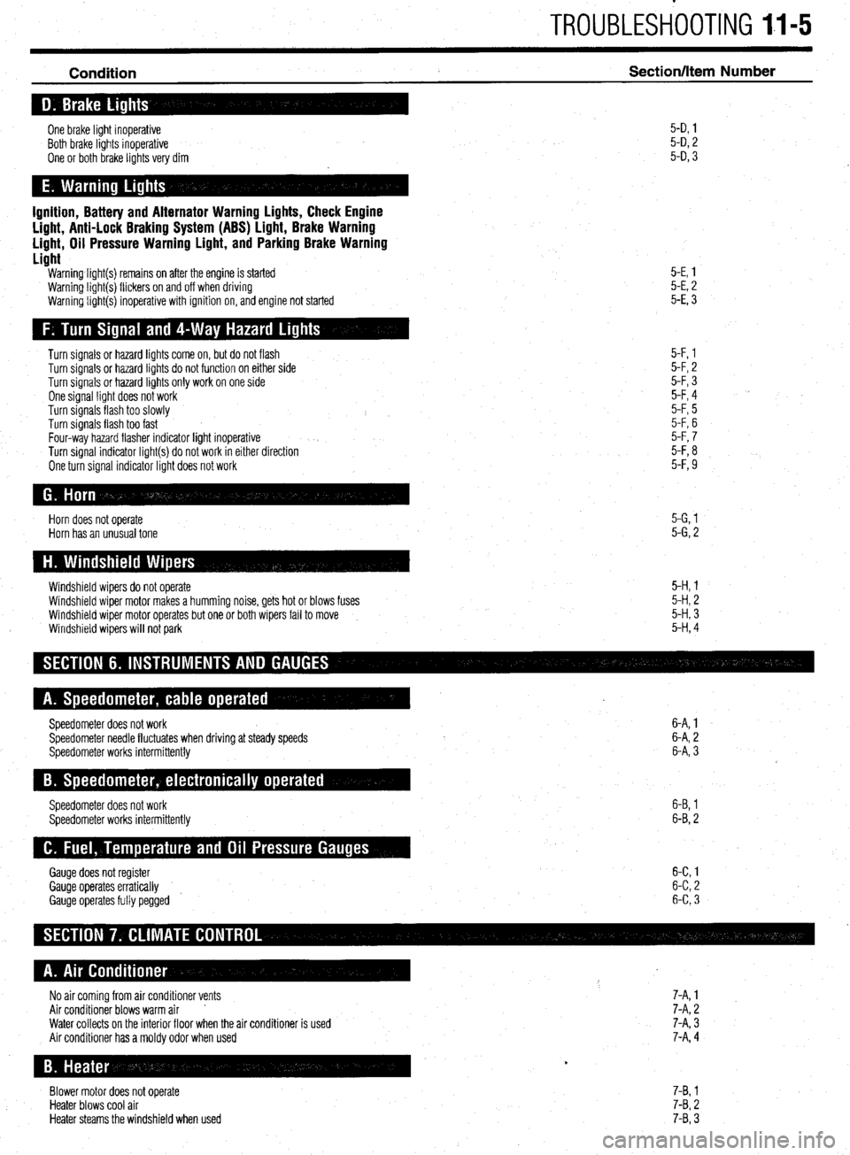
TROUBLESHOOTING II-5
Condition Section/Item Number
One brake light inoperative
Both brake lights inoperative
One or both brake lights very dim 5-D, 1
5-D, 2
5-D, 3
Ignition, Battery and Alternator Warning Lights, Check Engine
Light, Anti-Lock Braking System (ABS) Light, Brake Warning
Light, Oil Pressure Warning Light, and Parking Brake Warning
Light
Warning light(s) remains on after the engine is started
Warning light(s) flickers on and off when driving
Warning light(s) inoperative with ignition on, and engine not started 5-E, 1
5-E, 2
5-E, 3
Turn signals or hazard lights come on, but do not flash
Turn signals or hazard lights do not function on either side
Turn signals or hazard lights only work on one side
One signal light does not work
Turn signals flash too slowly
Turn signals flash too fast
Four-way hazard flasher indicator light inoperative
Turn signal indicator light(s) do not work in either direction
One turn signal indicator light does not work 5-F, 1
5-F, 2
5-F, 3
5-F, 4
5-F, 5
5-F, 6
5-F, 7
5-F, 8
5-F, 9
Horn does not operate
Horn has an unusual tone 5-G, 1
5-G, 2
Windshield wipers do not operate
Windshield wiper motor makes a humming noise, gets hot or blows fuses
Windshield wiper motor operates but one or both wipers fail to move
Windshield wipers will not park 5-H, 1
5-H, 2
5-H, 3
5-H, 4
Speedometer does not work
Speedometer needle fluctuates when driving at steady speeds
Speedometer works intermittently 6-A, 1
6-A, 2
6-A, 3
Speedometer does not work
Speedometer works intermittently 6-B, 1
6-B, 2
Gauge does not register 6-C 1
Gauge operates erratically 6-C 2
’
Gauge operates fully pegged 6-C 3
No air coming from air conditioner vents 7-A, 1
Air conditioner blows warm air ’ 7-A, 2
Water collects on the interior floor when the air conditioner is used
Air conditioner has a moldy odor when used 7-A, 3
7-A, 4
Blower motor does not operate
Heater blows cool air
Heater steams the windshield when used 7-B, 1
7-B, 2
7-B, 3
Page 396 of 408
II-14 TROUBLESHOOTING
b. Check for low voltage at the bulb socket positive terminal or a poor ground. If voltage
is low, or the ground marginal, trace the wiring to, and check for loose, damaged or
corroded wires and electrical terminals; repair as necessary.
c. Check the light switch operation and replace if necessary.
1. Interior light inoperative
a. Verify the interior light switch location and position(s), and set the switch in the cor-
rect position.
b. Check for battery voltage and ground at the interior light bulb socket. If battery voltage
and ground are present, replace the bulb. If voltage is not present, check the interior
light fuse for battery voltage. If the fuse is missing, replace the fuse. If the fuse has
blown, or if battery voltage is present, refer to the wiring diagram to troubleshoot the
cause for an open or shorted circuit. If ground is not present, check the door switch
contacts and clean or repair as necessary.
2. Interior light works intermittent/y
a. Check the bulb for a damaged filament, and replace if damaged.
b. Check the bulb and bulb socket for corrosion, and clean or replace the bulb and
socket.
c. Check for loose, damaged or corroded wires and electrical terminals; repair as neces-
sary.
d. Check the door and light switch operation, and replace if necessary.
3. Interior light very dim
a. Check the bulb and bulb socket for corrosion, and clean or replace the bulb and
socket.
b. Check for low voltage at the bulb socket positive terminal or a poor ground. If voltage
is low, or the ground marginal, trace the wiring to, and check for loose, damaged or
corroded wires and electrical terminals; repair as necessary.
c. Check the door and light switch operation, and replace if necessary.
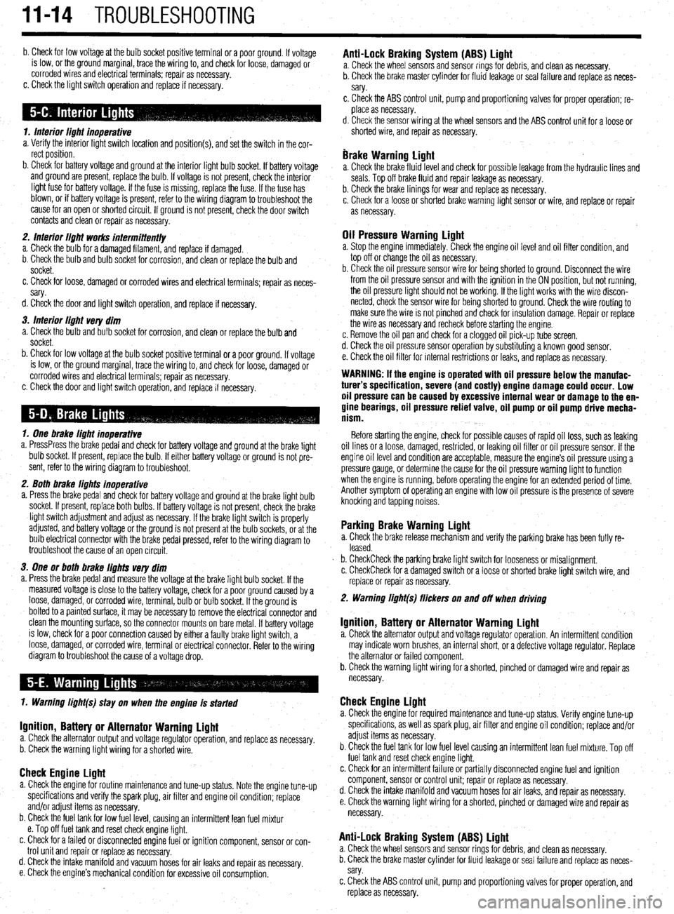
1. One brake light inoperative
a. PressPress the brake pedal and check for battery voltage and ground at the brake light
bulb socket. If present, replace the bulb. If either battery voltage or ground is not pre-
sent, refer to the wiring diagram to troubleshoot.
2. Both brake lights inoperative
a. Press the brake pedal and check for battery voltage and grou’nd at the brake light bulb
socket. If present, replace both bulbs. If battery voltage is not present, check the brake
light switch adjustment and adjust as necessary. If the brake light switch is properly
adjusted, and battery voltage or the ground is not present at the bulb sockets, or at the
bulb electrical connector with the brake pedal pressed, refer to the wiring diagram to
troubleshoot the cause of an open circuit.
3. One or both brake lights very dim
a. Press the brake pedal and measure the voltage at the brake light bulb socket. If the
measured voltage is close to the battery voltage, check for a poor ground caused by a
loose, damaged, or corroded wire, terminal, bulb or bulb socket. If the ground is
bolted to a painted surface, it may be necessary to remove the electrical connector and
clean the mounting surface, so the connector mounts on bare metal. If battery voltage
is low, check for a poor connection caused by either a faulty brake light switch, a
loose, damaged, or corroded wire, terminal or electrical connector. Refer to the wiring
diagram to troubleshoot the cause of a voltage drop.
1. Warning light(s) stay on when the engine is started
Ignition, Battery or Alternator Warning light a. Check the alternator output and voltage regulator operation, and replace as necessary.
b. Check the warning light wiring for a shorted wire.
Check Engine Light a. Check the engine for routine maintenance and tune-up status. Note the engine tune-up
specifications and verify the spark plug, air filter and engine oil condition; replace
and/or adjust items as necessary.
b. Check the fuel tank for low fuel level, causing an intermittent lean fuel mixtur
e. Top off fuel tank and reset check engine light.
c. Check for a failed or disconnected engine fuel or ignition component, sensor or con-
trol unit and repair or replace as necessary.
d. Check the intake manifold and vacuum hoses for air leaks and repair as
necessary.
e. Check the engine’s mechanical condition for excessive oil consumption.
Anti-Lock Braking System (ABS) Light a. Check the wheel sensors and sensor rings for debris, and clean as necessary.
b. Check the brake master cylinder for fluid leakage or seal failure and replace as neces-
sary.
c, Check the ABS control unit, pump and proportioning valves for proper operation; re-
place as necessary.
d. Check the sensor wiring at the wheel sensors and the ABS control unit for a loose or
shorted wire, and repair as necessary.
brake Warning Light a. Check the brake fluid level and check for possible leakage from the hydraulic lines and
seals. Top off brake fluid and repair leakage as necessary.
b. Check the brake linings for wear and replace as necessary.
c. Check for a loose or shot-ted brake warning light sensor or wire, and replace or repair
as necessary.
Oil Pressure Warning Light a. Stop the engine immediately. Check the engine oil level and oil filter condition, and
top off or change the oil as necessary.
b. Check the oil pressure sensor wire for being shorted to ground. Disconnect the wire
from the oil pressure sensor and with the ignition in the ON position, but not running,
the oil pressure light should not be working. If the light works with the wire discon-
nected, check the sensor wire for being shorted to ground. Check the wire routing to
make sure the wire is not pinched and check for insulation damage. Repair or replace
the wire as necessary and recheck before starting the engine.
c. Remove the oil pan and check for a clogged oil pick-up tube screen.
d. Check the oil pressure sensor operation by substituting a known good sensor.
e. Check the oil filter for internal restrictions or leaks, and replace as necessary.
WARNING: If the engine is operated with oil pressure below the manufac-
turer’s specification, severe (and costly) engine damage could occur. Low
oil pressure can be caused by excessive internal wear or damage to the en-
gine bearings, oil pressure relief valve, oil pump or oil pump drive mecha-
nism.
Before starting the engine, check for possible causes of rapid oil loss, such as leaking
oil lines or a loose, damaged, restricted, or leaking oil filter or oil pressure sensor. If the
engine oil level and condition are acceptable, measure the engine’s oil pressure using a
pressure gauge, or determine the cause for the oil pressure warning light to function
when the engine is running, before operating the engine for an extended period of time.
Another symptom of operating an engine with low oil pressure is the presence of severe
knocking and tapping noises.
Parking Brake Warning Light a. Check the brake release mechanism and verify the parking brake has been fully re-
leased.
b. CheckCheck the parking brake light switch for looseness or misalignment.
c. CheckCheck for a damaged switch or a loose or shorted brake light switch wire, and
replace or repair as necessary.
2. Warning light(s) flickers on and off when driving
Ignition, Battery or Alternator Warning Light a. Check the alternator output and voltage regulator operation. An intermittent condition
may indicate worn brushes, an internal short, or a defective voltage regulator. Replace
the alternator or failed component.
b. Check the warning light wiring for a shorted, pinched or damaged wire and repair as
necessary.
Check Engine Light a. Check the engine for required maintenance and tune-up status. Verify engine tune-up
specifications, as well as spark plug, air filter and engine oil condition; replace and/or
adjust items as necessary.
b. Check the fuel tank for low fuel level causing an intermittent lean fuel mixture. Top off
fuel tank and reset check engine light.
c. Check for an intermittent failure or partially disconnected engine fuel and ignition
component, sensor or control unit; repair or replace as necessary.
d. Check the intake manifold and vacuum hoses for air leaks, and repair as necessary.
e. Check the warning light wiring for a shorted, pinched or damaged wire and repair as
necessary.
Anti-Lock Braking System (ABS) Light a. Check the wheel sensors and sensor rings for debris, and clean as necessary.
b. Check the brake master cylinder for fluid leakage or seal failure and replace as neces-
sary.
c. Check the ABS control unit, pump and proportioning valves for proper operation, and
replace as necessary.
Page 397 of 408
TROUBLESHOOTING 1145
d. Check the sensor wiring at the wheel sensors and the ABS control unit for a loose or
shorted wire and repair as necessary.
Brake Warninu Liaht a. Check the brakefluid~evel and check for possible leakage from the hydraulic lines and
seals. Top off brake fluid and repair leakage as necessary.
b. Check the brake linings for wear and replace as necessary.
c. Check for a loose or shorted brake warning light sensor or wire, and replace or repair
as necessary.
Oil Pressure Warning Light a. Stop the engine immediately. Check the engine oil level and check for a sudden and
rapid oil loss, such as a leaking oil line or oil pressure sensor, and repair or replace as
necessary.
b. Check the oil pressure sensor operation by substituting a known good sensor.
c. Check the oil pressure sensor wire for being shorted to ground. Disconnect the wire
from the oil pressure sensor and with the ignition in the ON position, but not running,
the oil pressure light should not be working. If the light works with the wire discon-
nected, check the sensor wire for being shorted to ground. Check the wire routing to
make sure the wire is not pinched and check for insulation damage. Repair or replace
the wire as necessary and recheck before starting the engine.
d. Remove the oil pan and check for a clogged oil pick-up tube screen.
Parking Brake Warning Light a. Check the brake release mechanism and verify the parking brake has been fully re-
leased.
b. Check the parking brake light switch for looseness or misalignment.
c. Check for a damaged switch or a loose or shorted brake light switch wire, and replace
or repair as necessary.
3. Warning li#ht(s) inoperative with iflnition on,
and engine not started
a. Check for a defective bulb by installing a known good bulb.
b. Check for a defective wire using the appropriate wiring diagram(s).
c. Check for a defective sending unit by removing and then grounding the wire at the
sending unit. If the light comes on with the ignition on when grounding the wire, re-
place the sending unit.
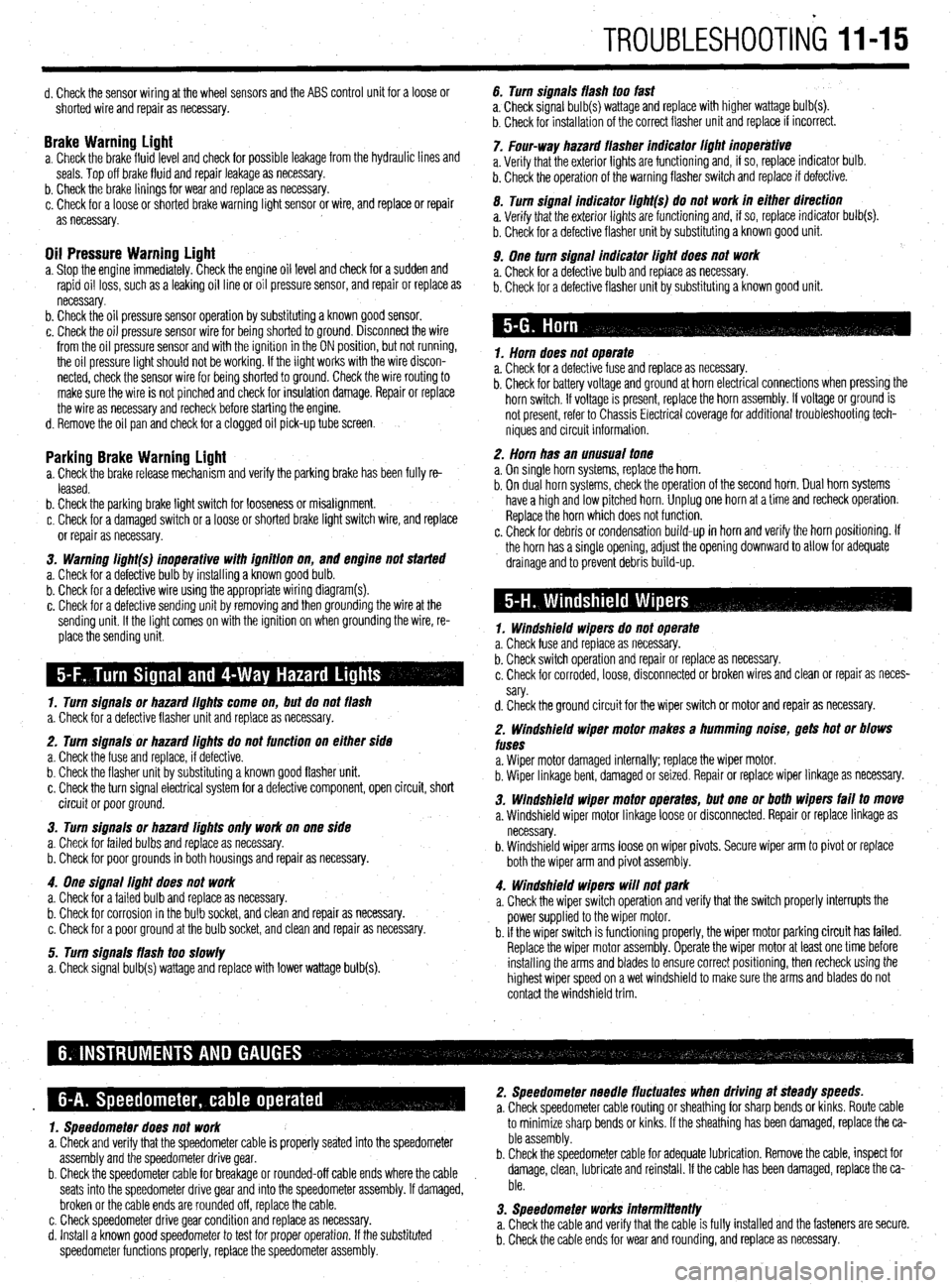
1. Turn siflnais or hazard iiflhts come on, but do not flash
a. Check for a defective flasher unit and replace as necessary.
2. Turn signals or hazard iiflhts do not function on either side
a. Check the fuse and replace, if defective.
b. Check the flasher unit by substituting a known good flasher unit.
c. Check the turn signal electrical system for a defective component, open circuit, short
circuit or poor ground.
3. Turn siflnais or hazard lights only work on one side
a. Check for failed bulbs and replace as necessary.
b. Check for poor grounds in both housings and repair as necessary.
4. One siflnai light does not work
a. Check for a failed bulb and replace as necessary.
b. Check for corrosion in the bulb socket, and clean and repair as necessary.
c. Check for a poor ground at the bulb socket, and clean and repair as necessary.
5. Turn signals flash too slowly
a. Check signal bulb(s) wattage and replace with lower wattage bulb(s). 6. Turn signals flash too fast
a, Check signal bulb(s) wattage and replace with higher wattage bulb(s).
b. Check for installation of the correct flasher unit and replace if incorrect.
7. Four-way hazard flasher indicator iiflhi inoperative
a. Verify that the exterior lights are functioning and, if so, replace indicator bulb.
b. Check the operation of the warning flasher switch and replace if defective.
0. Turn signal indicator ii#ht(s) do not work in either direction
a. Verify that the exterior lights are functioning and, if so, replace indicator bulb(s).
b. Check for a defective flasher unit by substituting a known good unit.
9. One turn signal indicator liflht does not work
a. Check for a defective bulb and replace as necessary.
b. Check for a defective flasher unit by substituting a known good unit.
1. Horn does not operate
a. Check for a defective fuse and replace as necessary.
b. Check for battery voltage and ground at horn electrical connections when pressing the
horn switch. If voltage is present, replace the horn assembly. If voltage or ground is
not present, refer to Chassis Electrical coverage for additional troubleshooting tech-
niques and circuit information.
2. Horn has an unusual tone
a. On single horn systems, replace the horn.
b. On dual horn systems, check the operation of the second horn. Dual horn systems
have a high and low pitched horn. Unplug one horn at a time and recheck operation.
Replace the horn which does not function.
c. Check for debris or condensation build-up in horn and verify the horn positioning. If
the horn has a single opening, adjust the opening downward to allow for adequate
drainage and to prevent debris build-up.
1. Windshield wipers do not operate
a. Check fuse and replace as necessary.
b. Check switch operation and repair or replace as necessary.
c. Check for corroded, loose, disconnected or broken wires and clean or repair as neces-
sary.
d. Check the ground circuit for the wiper switch or motor and repair as necessary.
2. Windshield wiper motor makes a humming noise, gets hot or blows
fuses
a. Wiper motor damaged internally; replace the wiper motor.
b. Wiper linkage bent, damaged or seized. Repair or replace wiper linkage as necessary.
3. Windshield wiper motor operates, but one or both wipers fail to move
a. Windshield wiper motor linkage loose or disconnected. Repair or replace linkage as
necessary.
b. Windshield wiper arms loose on wiper pivots. Secure wiper arm to pivot or replace
both the wiper arm and pivot assembly.
4. Windshield wipers will not park
a. Check the wiper switch operation and verify that the switch properly interrupts the
power supplied to the wiper motor.
b. If the wiper switch is functioning properly, the wiper motor parking circuit has failed.
Replace the wiper motor assembly. Operate the wiper motor at least one time before
installing the arms and blades to ensure correct positioning, then recheck using the
highest wiper speed on a wet windshield to make sure the arms and blades do not
contact the windshield trim.
1. Speedometer does not work to minimize sharp bends or kinks.
If the sheathing has been
damaged, replace the ca-
a. Check and verify that the speedometer cable is properly seated into the speedometer ble assembly.
assembly and the speedometer drive gear. b. Check the speedometer cable for adequate lubrication. Remove the cable, inspect for
b. Check the speedometer cable for breakage or rounded-off cable ends where the cable damage, clean, lubricate and reinstall. If the cable has been damaged, replace the ca-
seats into the speedometer drive gear and into the speedometer assembly. If damaged, ble.
broken or the cable ends are rounded off, replace the cable.
c. Check speedometer drive gear condition and replace as necessary. 3. Speedometer works intermittently
d. Install a known good speedometer to test for proper operation. If the substituted a. Check the cable and verify that the cable is fully installed and the fasteners are secure.
speedometer functions properly, replace the speedometer assembly. b. Check the cable ends for wear and rounding, and replace as necessary.