wipers MITSUBISHI DIAMANTE 1900 Repair Manual
[x] Cancel search | Manufacturer: MITSUBISHI, Model Year: 1900, Model line: DIAMANTE, Model: MITSUBISHI DIAMANTE 1900Pages: 408, PDF Size: 71.03 MB
Page 1 of 408
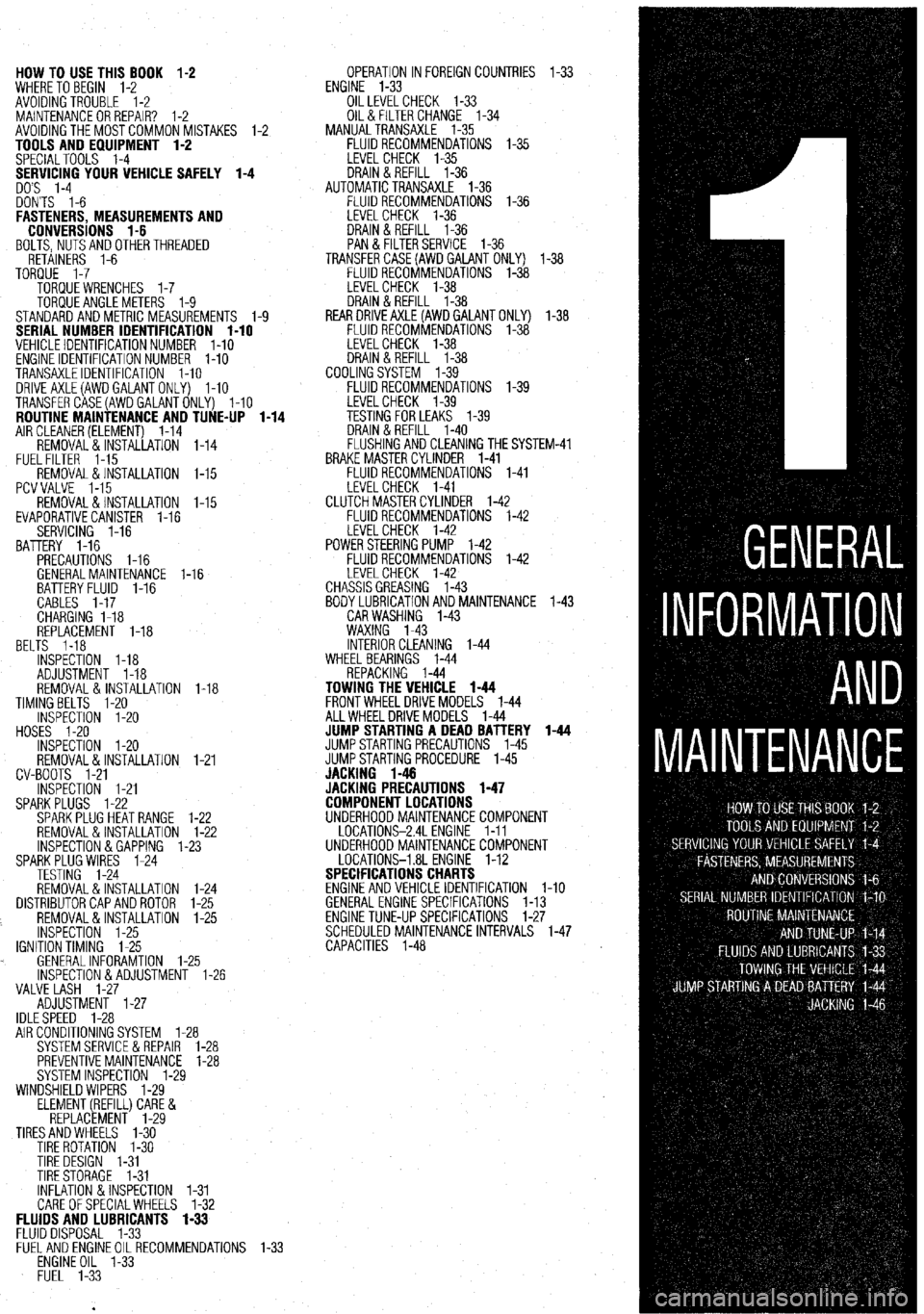
HOW TO USE THIS BOOK 1-2
WHERE TOBEGIN l-2
AVOIDINGTROUBLE 1-2
MAINTENANCEORREPAIR? 1-2
AVOIDINGTHEMOSTCOMMONMISTAKES l-2
TOOLS AND EQUIPMENT 1-2
SPECIALTOOLS l-4
YOUR VEHICLE SAFELY 1-4
DON'TS l-6
FASTENERS, MEASUREMENTS AND
CONVERSIONS l-6
BOLTS,NUTSANDOTHERTHREADED
RETAINERS 1-6
TORQUE l-7
TORQUEWRENCHES l-7
TORQUEANGLEMETERS 1-9
STANDARDANDMETRIC MEASUREMENTS l-9
SERIAL NUMBER IDENTIFICATION l-10
VEHICLE IDENTIFICATION NUMBER l-10
ENGINE IDENTIFICATION NUMBER I-10
TRANSAXLEIDENTIFICATION I-10
DRlVEAXLE(AWDGALANTONLY) l-10
TRANSFERCASE(AWDGALANTONLY) l-10
ROUTINE MAINTENANCE AND TUNE-UP l-14
AIRCLEANER(ELEMENT) 1-14
REMOVAL&INSTALLATION 1-14
FUELFILTER 1-15
REMOVAL &INSTALLATION l-15
PCVVALVE l-15
REMOVAL&INSTALLATION l-15
EVAPORATIVECANISTER l-16
SERVICING 1-16
BATTERY 1-16
PRECAUTIONS I-16
GENERALMAINTENANCE 1-16
BEL BATTERYFLUID 1-16
CABLES I-17
CHARGING I-18
REPLACEMENT 1-18
TS 1-18
INSPECTiON l-18
ADJUSTMENT 1-18
REMOVAL&INSTALLATION 1-18
TIMINGBELTS l-20
INSPECTION l-20
HOSES I-20
INSPECTION l-20
REMOVAL&INSTALLATION
CV-BOOTS 1-21
INSPECTION l-21
SPARKPLUGS l-22
SPARKPLUGHEATRANGE
REMOVAL&INSTALLATION
INSPECTION &GAPPING 1.
SPARKPLUG WIRES 1-24
TESTING 1-24
REMOVAL&INSTALLATION
DISTRIBUTORCAPANDROTOR
REMOVAL&INSTALLATION
INSPECTION 1-25
IGNITIONTIMING 1-25
. GENERALINFORAMTION l-
lNSPECTlON&ADJUSTMENl
VALVE LASH l-27
ADJUSTMENT l-27
IDLESPEED 1-28 1-21
l-22
l-22
-23
1-24
l-25
l-25
.25
1-26
AIR CONDITIONING SYSTEM 1-28
SYSTEMSERVlCEiiREPAlR l-28
PREVENTIVEMAINTENANCE 1-28
SYSTEM INSPECTION l-29
WINDSHIELD WIPERS l-29
ELEMENT(REFILL)CARE&
REPLACEMENT l-29
TIRESANDWHEELS l-30
TIRE ROTATION I-30
TIRE DESIGN 1-31
TIRESTORAGE l-31
INFLATION &INSPECTION l-31
CARE OFSPECIALWHEELS l-32 OPERATION INFOREIGNCOUNTRIES l-33
ENGINE l-33
OILLEVELCHECK 1-33
OIL& FILTER CHANGE l-34
MANUALTRANSAXLE l-35
FLUIDRECOMMENDATIONS l-35
LEVELCHECK l-35
DRAIN&REFILL l-36
AUTOMATICTRANSAXLE l-36
FLUIDRECOMMENDATIONS l-36
LEVELCHECK 1-36
DRAIN&REFILL l-36
PAN & FILTERSERVICE 1-36
TRANSFERCASE(AWDGAlANT ONLY) l-38
FLUIDRECOMMENDATIONS l-38
LEVELCHECK l-38
DRAIN&REFILL l-38
REARDRlVEAXLE(AWDGALANTONLY) l-38
FLUIDRECOMMENDATIONS l-38
LEVELCHECK l-38
DRAIN&REFILL l-38
COOLINGSYSTEM l-39
FLUIDRECOMMENDATIONS l-39
iM-41
FLUIDS AND LUBRICANTS 1-33
FLUID DISPOSAL 1-33
FlJELANDENGlNEOILRECOMMENDATlONS
ENGINE OIL l-33
FUEL l-33
Page 28 of 408
GENERALINFORMATIONAND MAlNTENANdE 1-29
i
*Bug screens which are mounted in front of
the condenser (unless they are original
equipment) are regarded as obstructtons.
l The condensation drain tube expels any water
which accumulates on the bottom of the evaporator
housing into the engine compartment. If this tube is
obstructed, the air conditioning performance can be
restricted and condensation buildup can spill over
onto the vehicle’s floor.
l Make sure the air passage selection lever is
operating correctly. Start the engine and warm it to
normal operating temperature, then make sure the
temperature selection lever is operating correctly.
-w
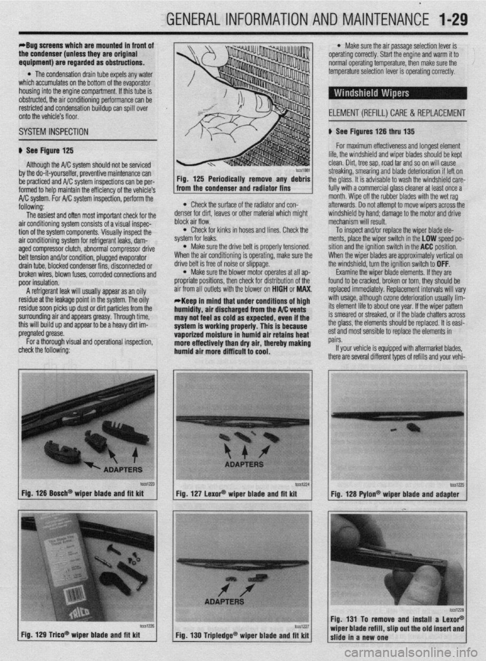
~1 ELEMENT(REFILL)CARE& REPLACEMENT
SYSTEM INSPECTION
b See Figure 125 b See Figures 126 thru 135
For maximum effectiveness and longest element
Although the A/C system should not be serviced
by the do-it-yourselfer, preventive maintenance can
be practiced and A/C system inspections can be per-
formed to help maintain the efficiency of the vehicle’s
A/C system. For A/C system inspection, perform the
following:
The easiest and often most important check for the
air conditioning system consists of a visual inspec-
tion of the system components. Visually inspect the
air conditioning system for refrigerant leaks, dam-
aged compressor clutch, abnormal compressor drive
belt tension and/or condition, plugged evaporator
drain tube, blocked condenser fins, disconnected or
broken wires, blown fuses, corroded connections and
poor insulation.
A refrigerant leak will usually appear as an oily
residue at the leakage point in the system. The oily
residue soon picks up dust or dirt particles from the
surrounding air and appears greasy. Through time,
this will build up and appear to be a heavy dirt im-
pregnated grease.
For a thorough visual and operational inspection,
check the following: * Check the surface of the radiator and con-
denser for dirt, leaves or other material which might
block air flow.
l Check for kinks in hoses and lines. Check the
system for leaks.
l Make sure the drive belt is properly tensioned.
When the air conditioning is operating, make sure the
drive belt is free of noise or slippage.
l Make sure the blower motor operates at all ap-
propriate positions, then check for distribution of the
air from all outlets with the blower on HIGH or MAX.
*Keep in mind that under conditions of high
humidity, air discharged from the A/C vents
may not feel as cold as expected, even if the
system is working properly. This is because
vaporized moisture in humid air retains heat
more effectively than dry air, thereby making
humid air more difficult to cool.
lifp thp winrkhi&i nnri winor hlarlP~ shmM hP kmt . ..“. .I.” . . * ““I.. “.” I..” ...r”* “.“““” “, ,““,” “” ,~“r~ clean. Dirt, tree sap, road tar and so on will cause
streaking, smearing and blade deterioration if left on
the glass. It is advisable to wash the windshield care-
fully with a commercial glass cleaner at least once a
month. Wipe off the rubber blades with the wet rag
afterwards. Do not attempt to move wipers across the
windshield by hand; damage to the motor and drive
mechanism will result.
To inspect and/or replace the wiper blade ele-
ments, place the wiper switch in the LOW speed po-
sition and the ignition switch in the ACC position.
When the wiper blades are approximately vertical on
the windshield, turn the ignition switch to OFF.
Examine the wiper blade elements. If they are
found to be cracked, broken or torn, they should be
replaced immediately. Replacement intervals will vary
with usage, although ozone deterioration usually lim-
its element life to about one year. If the wiper pattern
is smeared or streaked, or if the blade chatters across
the glass, the elements should be replaced. It is easi-
est and most sensible to replace the elements in
pairs.
If your vehicle is equipped with aftermarket blades,
there are several different types of refills and your vehi-
tcca-23 Fig. 126 Bosch@ wiper blade and fft kit
Fig. 129 T&o* wioer blade and fit kit tCS1224
lW1Z?5 Fig. 127 LexoP wiper blade and fit kit
Fig. 128 Pylon@ wiper blade and adapter
Fig. 131 To remove and install a LexoP
Fig, 130 Tripledge@ wiper blade and fit kit wiper blade refill, slip out the old insert and
slide in a new one
Page 42 of 408
GENERALINFORMATIONAND MAINTENANCE l-43
l Special car washing detergent is the best to
use. Liquid dishwashing detergent can remove wax
and leave the car’s paint unprotected and in addition
some liquid detergents contains abrasives which can
scratch the paint.
l Bird droppings should be removed from the
paintwork as soon as possible, otherwise the finish
may be permanently stained.
When the car is driven immediately after be-
ing washed, apply the brakes several times
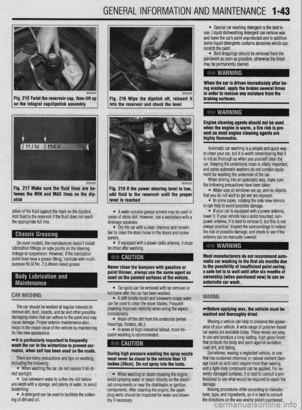
93151p14 93151p12 Fig. 215 Twist the reservoir cap, then lift up
I I
in order to remove any moisture from the
Fig. 216 Wipe the dipstick off, reinsert it braking surfaces.
on the integral cap/dipstick assembly
into the reservoir and check the level
I
Engine cleaning agents should not be used
when the engine is warm, a fire risk is pre-
sent as most engine cleaning agents are
highly flammable.
sition of the fluid against the mark on the dipstick,
Add fluid to the reservoir if the fluid does not reach
the appropriate full line.
On most models, the manufacturer doesn’t install
lubrication fittings on lube points on the steering
linkage or suspension. However, if the lubrication
point does have a grease fitting, lubricate with multi-
purpose NLGI No. 2 (Lithium base) grease.
CAR WASHING
The car should be washed at regular intervals to
remove dirt, dust, insects, and tar and other possibly
damaging stains that can adhere to the paint and may
cause damage. Proper exterior maintenance also
helps in the resale value of the vehicle by maintaining
its like-new appearance.
Mt is particularly important ta frequentiy
wash the car in the wintertime to prevent cor-
rosion, when salt has been used on the roads.
There are many precautions and tips on washing,
including the following:
l When washing the car, do not expose it do di-
rect sunlight.
. Use lukewarm water to soften the dirt before
you wash with a sponge, and plenty of water, to avoid
scratching.
l A detergent can be used to facilitate the soften-
ing of dirt and oil. * A water-soluble grease solvent may be used in
cases of sticky dirt. However, use a washplace with a
drainage separator.
l Dry the car with a clean chamois and remem-
ber to clean the drain holes in the doors and rocker
panels.
l If equipped with a power radio antenna, it must
be dried after washing.
Never clean the bumpers with gasoline or
paint thinner, always use the same agent as
used on the painted surfaces of the vehicle.
l Tar spots can be removed with tar remover or
kerosene after the car has been washed.
l A stiff-bristle brush and lukewarm soapy water
can be used to clean the wiper blades. Frequent
cleaning improves visibility when using the wipers
considerably.
l Wash off the did from the underside (wheel
housings, fenders, etc.).
l In areas of high industrial fallout, more fre-
quent washing is recommended.
During high pressure washing the spray nonle
must never be closer to the vehicle than 13
inches (30cm). Do not spray into the locks.
l When washing or steam cleaning the engine,
avoid spraying water or steam directly on the electri-
cal components or near the distributor or ignition
components. After cleaning the engine, the spark
plug wells should be inspected for water and blown
dry if necessary. Automatic car washing is a simple and quick way
to clean your car, but it is worth remembering that it
is not as thorough as when you yourself clean the
car. Keeping the underbody clean is vitally important,
and some automatic washers do not contain equip-
ment for washing the underside of the car.
When driving into an automatic was, make sure
the following precautions have been taken:
l Make sure all windows are up, and no objects
that you do not want to get wet are exposed.
l In some cases, rotating the side view mirrors
in can help to avoid possible damage.
l If your car is equipped with a power antenna,
lower it. If your vehicle has a solid mounted, non-
power antenna, it is best to remove it, but this is not
always practical. Inspect the surroundings to reduce
the risk of possible damage, and check to see if the
antenna can be manually lowered.
Most manufacturers do not recommend auto-
matic car washing in the first six months due
to the possibility of insufficient paint curing;
a safe bet is to wait until after six months of
ownership (when purchased new) to use an
automatic car wash.
WAXING
eBefore applying wax, the vehicle must be
washed and thoroughly dried.
Waxing a vehicle can help to preserve the appear-
ante of your vehicle. A wide range of polymer-based
car waxes are available today. These waxes are easy
to use and produce a long-lasting, high gloss finish
that protects the body and paint against oxidation,
road dirt, and fading.
Sometimes, waxing a neglected vehicle, or one
that has sustained chemical or natural element dam-
age (such as acid rain) require more than waxing,
and a light-duty compound can be applied. For se-
verely damaged surfaces, it is best to consult a pro-
fessional to see what would be required to repair the
damage.
Waxing procedures differ according to manufac-
turer, type, and ingredients, so it is best to consult
the directions on the wax and/or polish purchased.
Page 56 of 408
ENGlNEELECTRldAL 2-9
TESTING
Voltage Test able for use by customers. An alternator
bench test is the most definitive way to de-
termine the condition of your alternator.
REMOVAL&INSTALLATION
1. Make sure the engine is OFF, and turn the 1.51,1.61, 1.6L, 2.OL and 2.4L Engines
headlights on for 15-20 seconds to remove any sur-
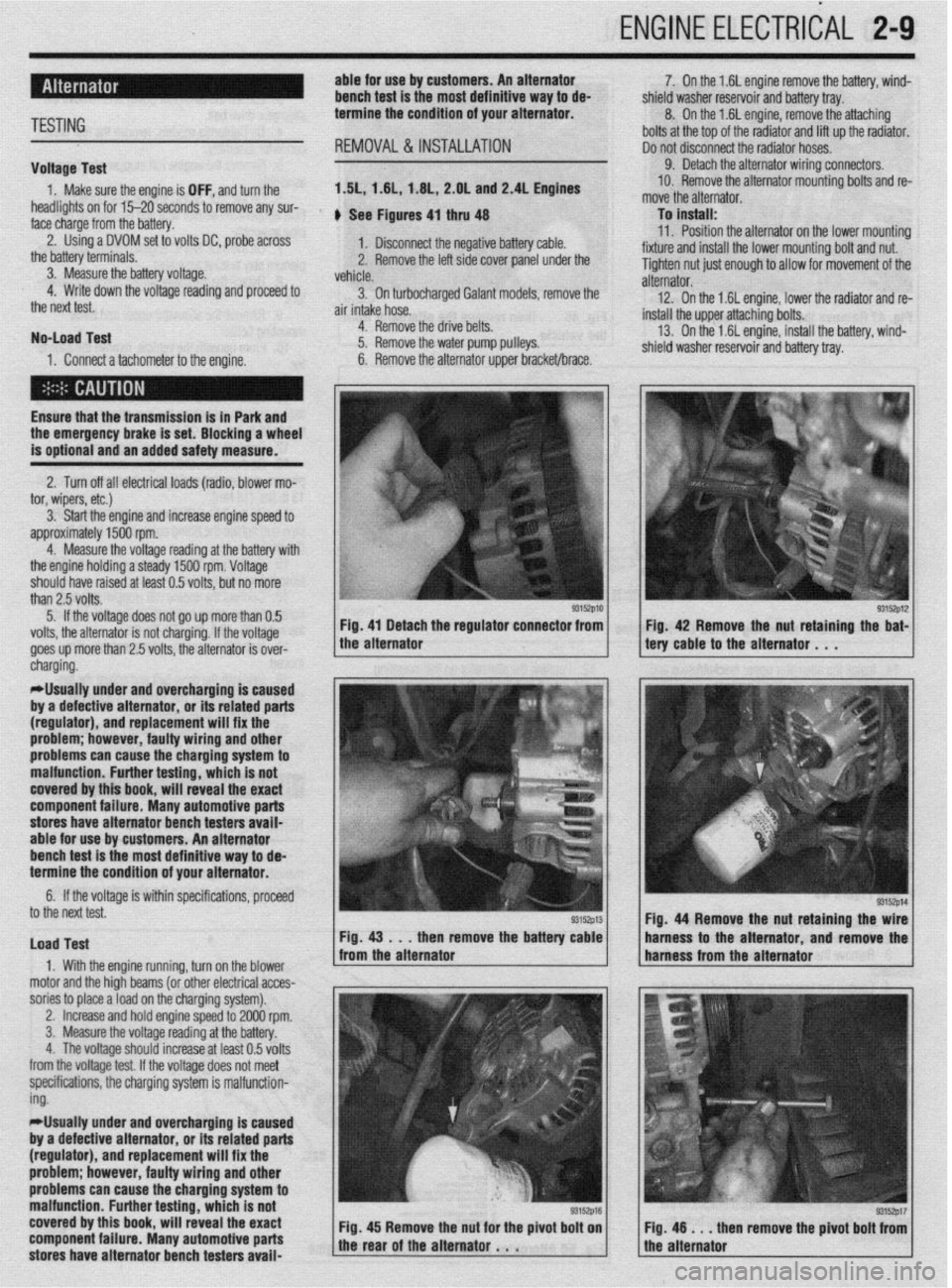
face charge from the battery. , See Figures 4, thru 48
2. Using a DVOM set to volts DC, probe across
1. Disconnect the negative battery cable.
the battery terminals.
3. Measure the battery voltage. 2. Remove the left side cover panel under the
vehicle.
4. Write down the voltage reading and proceed to
3. On turbocharaed Galant models, remove the
the next test.
air intake hose. -
No-load Test
1. Connect a tachometer to the engine. 4. Remove the drive belts.
5. Remove the water pump pulleys.
6. Remove the alternator upper bracket/brace.
Ensure that the transmission
is in Park and the emergency brake is set. Blocking a wheel
is optional and an added safety measure.
2. Turn off all electrical loads (radio, blower mo-
tor, wipers, etc.)
3. Start the engine and increase engine speed to
approximately 1500 rpm.
4. Measure the voltage reading at the battery with
the engine holding a steady 1500 rpm. Voltage
should have raised at least 0.5 volts, but no more
than 2.5 volts.
5. If the voltage does not go up more than 0.5
volts, the alternator is not charging. If the voltage
goes up more than 2.5 volts, the alternator is over-
* 7. On the 1.6L engine remove the battery, wind-
shield washer reservoir and battery tray.
8. On the 1.6L engine, remove the attaching
bolts at the top of the radiator and lift up the radiator.
Do not disconnect the radiator hoses.
9. Detach the alternator wiring connectors.
10. Remove the alternator mounting bolts and re-
move the alternator.
To install:
11. Position the alternator on the lower mountina
fixture and install the lower mounting bolt and nut. U
Tighten nut just enough to allow for movement of the
alternator.
12. On the 1.6L engine, lower the radiator and re-
install the upper attaching bolts.
13. On the 1.6L engine, install the battery, wind-
shield washer reservoir and battery tray.
/ tery cable to the alternator . , . 93152p12 Fig 42 Remove the nut retaining the bat-
cnargmg.
*Usually under and overcharging is‘caused
by a defective alternator, or its related parts
(regulator), and replacement will fix the
problem; however, faulty wiring and other
problems can
cause the charging system to
malfunction. Further testing, which is not
covered by this book, will reveal the exact
component failure. Many automotive parts
stores have alternator bench testers avaii-
able for use by customers. An alternator
bench test is the most definitive way to de-
termine the condition of your alternator.
6. If the voltage is within specifications, proceeU
to the next test.
Load Test
1. With the engine running, turn on the blower
motor and the hioh beams (or other electrical acces-
sories to place aioad on the charging system). Fig. 44 Remove the nut retaining the
then remove the batte harness to the alternator and remov
,
2. Increase and hold engine speed to 2000 rpm.
3. Measure the voltage reading at the battery.
4. The voltage should increase at least 0.5 volts
from the voltage test. If the voltage does not meet
specifications, the charging system is malfunction-
ing.
*Usually under and overcharging is caused
by a defective alternator, or its related parts
(regulator), and replacement will fix the
problem; however, faulty wiring and other
problems can cause the charging system to
malfunction. Further testing, which is not
covered by this book, will reveal the exact
component failure. Many automotive parts
stores have alternator bench testers avaii-
93152p17 en remove the pivot bolt from
Page 204 of 408
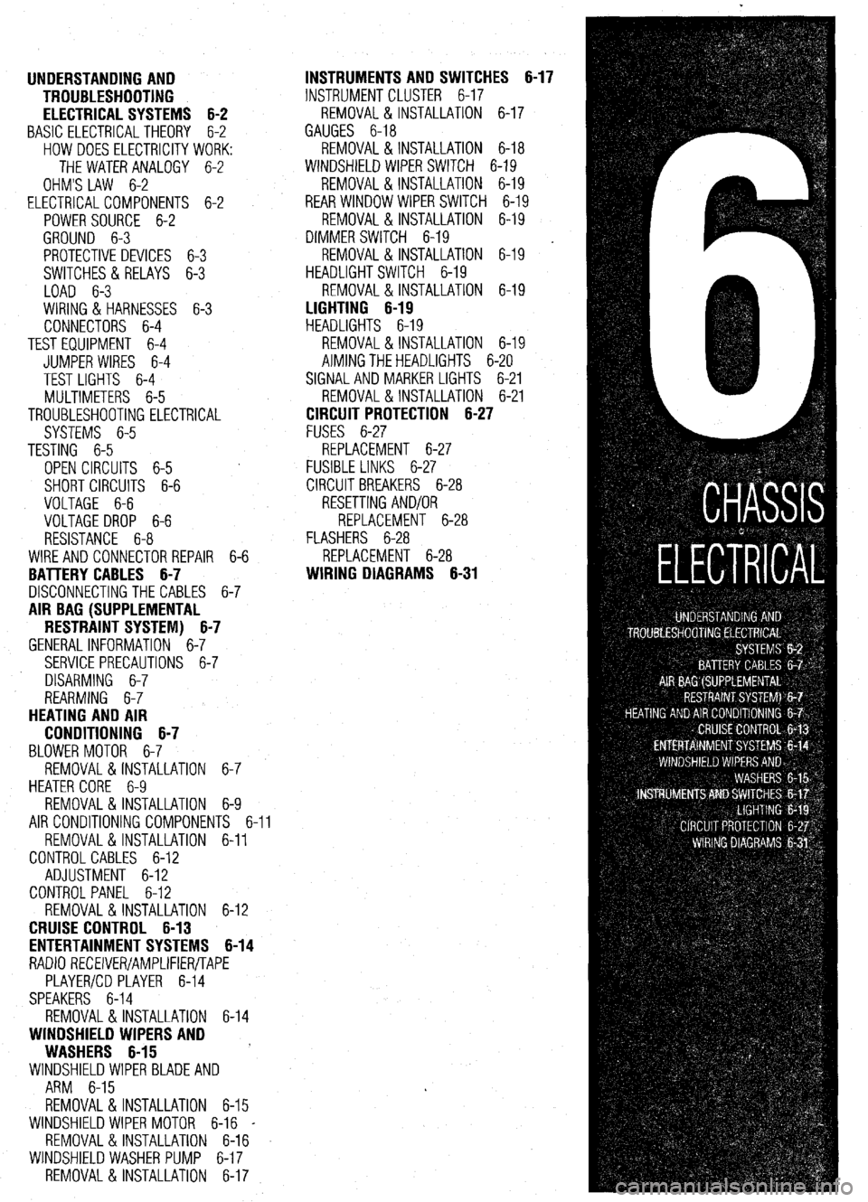
UNDERSTANDING AND
TROUBLESHOOTING
ELECTRICAL SYSTEMS 6-2
BASIC ELECTRICALTHEORY 6-2
HOW DOES ELECTRICITY WORK:
THEWATERANALOGY 6-2
OHM'S LAW 6-2
ELECTRICALCOMPONENTS 6-2
POWERSOURCE 6-2
GROUND 6-3
PROTECTIVE DEVICES 6-3
SWITCHES&RELAYS 6-3
LOAD 6-3
WIRING & HARNESSES 6-3
CONNECTORS 6-4
TEST EQUIPMENT 6-4
JUMPER WIRES 6-4
TEST LIGHTS 6-4
MULTIMETERS 6-5
TROUBLESHOOTING ELECTRICAL
SYSTEMS 6-5
TESTING 6-5
OPEN CIRCUITS 6-5
SHORT CIRCUITS 6-6
VOLTAGE 6-6
VOLTAGE DROP 6-6
RESISTANCE 6-8
WIRE AND CONNECTORREPAIR 6-6
BATTERY CABLES 6-7
DISCONNECTING THE CABLES 6-7
AIR BAG (SUPPLEMENTAL
RESTRAINT SYSTEM) 6-7
GENERALINFORMATION 6-7
SERVICE PRECAUTIONS 6-7
DISARMING 6-7
REARMING 6-7
HEATING AND AIR
CONDITIONING 6-7
BLOWER MOTOR 6-7
REMOVAL &INSTALLATION 6-7
HEATER CORE 6-9 INSTRUMENTS AND SWITCHES 6-17
INSTRUMENTCLUSTER 6-17
REMOVAL &INSTALLATION 6-17
GAUGES 6-18
REMOVAL&INSTALLATION 6-18
WINDSHIELD WIPER SWITCH 6-19
REMOVAL&INSTALLATION 6-19
REARWINDOWWIPERSWITCH 6-19
REMOVAL &INSTALLATION 6-19
DIMMER SWITCH 6-19
REMOVAL & INSTALLATION 6-19 .
HEADLIGHT SWITCH 6-19
REMOVAL & INSTALLATION 6-19
LIGHTING 6-19
HEADLIGHTS 6-19
REMOVAL &INSTALLATION 6-19
AIMINGTHEHEADLIGHTS 6-20
SIGNAL AND MARKER LIGHTS 6-21
REMOVAL &INSTALLATION 6-21
CIRCUIT PROTECTION 6-27
FUSES 6-27
REPLACEMENT 6-27
FUSIBLE LINKS 6-27
CIRCUIT BREAKERS 6-28
RESETTING AND/OR
REPLACEMENT 6-28
FLASHERS 6-28
REPLACEMENT 6-28
WIRING DIAGRAMS 6-31
REMOVAL & INSTALLATION 6-9
AIR CONDITIONING COMPONENTS 6-11
REMOVAL & INSTALLATION 6-11
CONTROLCABLES 6-12
ADJUSTMENT 6-12
CONTROL PANEL 6-12
REMOVAL & INSTALLATION 6-12
CRUISE CONTROL 6-13
ENTERTAINMENT SYSTEMS 6-14
RADIO RECEIVER/AMPLIFIER/TAPE
PLAYER/CD PLAYER 6-14
SPEAKERS 6-14
REMOVAL & INSTALLATION 6-14
WINDSHIELD WIPERS AND
WASHERS 6-15
WINDSHIELD WIPER BLADE AND
ARM 6-15
REMOVAL & INSTALLATION 6-15
WINDSHIELD WIPER MOTOR 6-16 _
REMOVAL &INSTALLATION 6-16
WINDSHIELD WASHER PUMP 6-17
REMOVAL &INSTALLATION 6-17
Page 210 of 408
I I
CHASSIS ELECTRICAL 6-7
When working on any electrical component on the
vehicle, it is always a good idea to disconnect the
negative (-) battery cable. This will prevent potential
damage to many sensitive electrical components
such as the Powertrain Control Module (PCM), radio,
alternator, etc.
*Any time you disengage the battery cables,
it is recommended that you disconnect the negative (-) battery cable first. This will pre-
vent your accidentally grounding the positive
(+) terminal to the body of the vehicle when
disconnecting it, thereby preventing damage
to the above mentioned components.
Before you disconnect the cable(s), first turn the
ignition to the OFF position. This will prevent a draw
on the battery which could cause arcing (electricity
trying to ground itself to the body of a vehicle, just
like a spark plug jumping the gap) and, of course, damaging some components such as the alternator
diodes.
When the battery cable(s) are reconnected (nega-
tive cable last), be sure to check that your lights,
windshield wipers and other electrically operated
safety components are all working correctly. If your
vehicle contains an Electronically Tuned Radio (ETR),
don’t forget to also reset your radio stations. Ditto for
the clock.
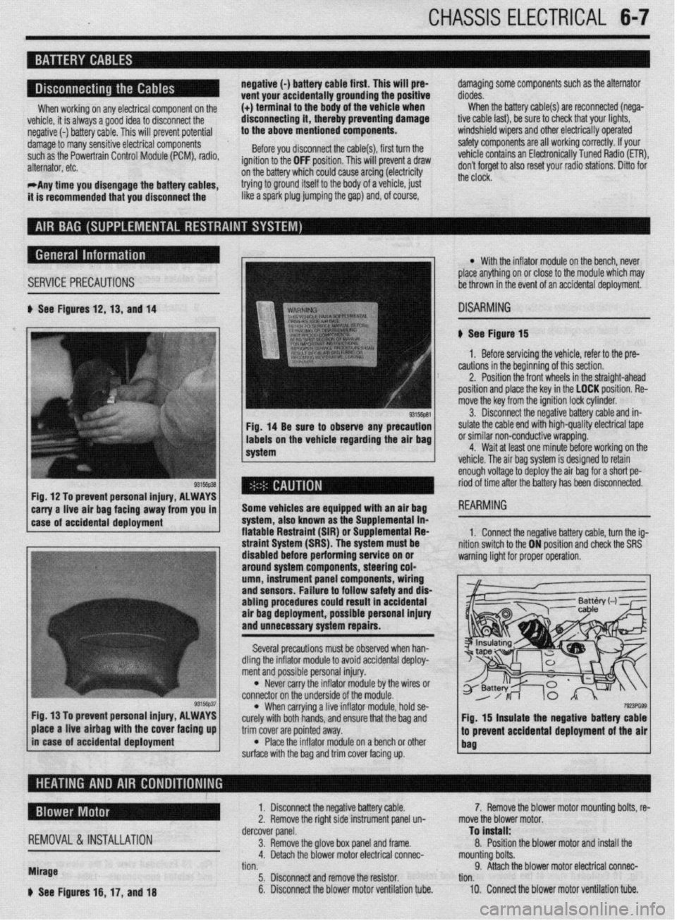
SERVICE PRECAUTIONS
b See Figures 12,13, and 14
Fig, 14 Be sure to observe any precaution
labels on the vehicle regarding the air bag
system
Fig. 12 To prevent personal injury, ALWAYS
*
carry a-live -ah bag fac!ng away from you in 1
1 case of accidental deployment Some vehicles are equipped wtth an air bag
-.-‘--
syr1em, aiscl Known as I11 -I-- ‘------- -- sLe Supplemental in- fiatable Restraint (SIR) o r Suouiementai Fiea
l With the inflator module on the bench, never
place anything on or close to the module which may
be thrown in the event of an accidental deployment.
DISARMING
# See Figure 15
1. Before servicing the vehicle, refer to the pre-
cautions in the beginning of this section.
2. Position the front wheels in the straight-ahead
position and place the key in the LOCK position. Re-
move the key from the ignition lock cylinder.
3. Disconnect the negative battery cable and in-
sulate the cable end with high-quality electrical tape
or similar non-conductive wrapping.
4. Wait at least one minute before working on the
vehicle. The air baa svstem is desianed to retain
enough voltage to deploy the air bag for a short pe-
riod of time after the battery has been disconnected.
1. Connect the neoative batters cable. turn the ia-
3, hold se-
e bag and
trim cover are pointed away.
l Place the inflator module on a bench or other
surface with the bag and trim cover facing up.
7!r!3PG93 Fig. 15 insulate the negative battery cable
.I
to prevent accidental deployment of the air
bag place a live airbag with the cover facing up
in case of accidental deployment
REMOVAL &INSTALLATION
Mirage
b See Figures 16, 17, and 18 1. Disconnect the negative battery cable.
2. Remove the right side instrument panel un-
dercover panel.
3. Remove the glove box panel and frame.
4. Detach the blower motor electrical connec-
tion.
5. Disconnect and remove the resistor.
6. Disconnect the blower motor ventilation tube. 7. Remove the blower motor mounting bolts, re-
move the blower motor.
To install:
8. Position the blower motor and install the
mounting bolts.
9. Attach the blower motor electrical connec-
tion.
10. Connect the blower motor ventilation tube.
Page 215 of 408
6-12 CHASSIS ELECTRICAL
personal injury or death, and because of the legal
ramifications of servicing these components without
the proper EPA certification and experience. Cost,
personal injury or death, environmental damage, and
legal considerations (such as the fact that it is a fed-
eral crime to vent refrigerant into the atmosphere),
dictate that the A/C comoonents on your vehicle 4. Move the air selection controi lever to the RE-
CIRC position. Move the air selection damper FULLY
INWARD and connect the cable to the lever. Adjust as
required. C. Push the outer cable in the direction of the
arrow so that there is no looseness, then secure
should be serviced only’by a Motor Vehicle Air Con-
ditioning (MVAC) trained, and EPA certified automo-
REMOVAL&INSTALLATION tive technician. with the clip.
d. Set the knob for the air outlet changeover
on the control to the DEF position.
e. Set the air outlet changeover damper lever
of the heater unit to the DEF position, then attach
the cable to the lever pin.
f. Push the outer cable in the direction of the
arrow so there is no loosen&s, then secure it
with the clip. *If your vehicle’s A/C system uses R-12 re-
frlgerant and is in need of recharging, the
AK system can be converted over to R-Ma
refrigerant (less environmentally harmful
and expensive). Refer to Section 1 for addi-
tional information on R-12 to R-134a eonver-
sions, and for additional considerations
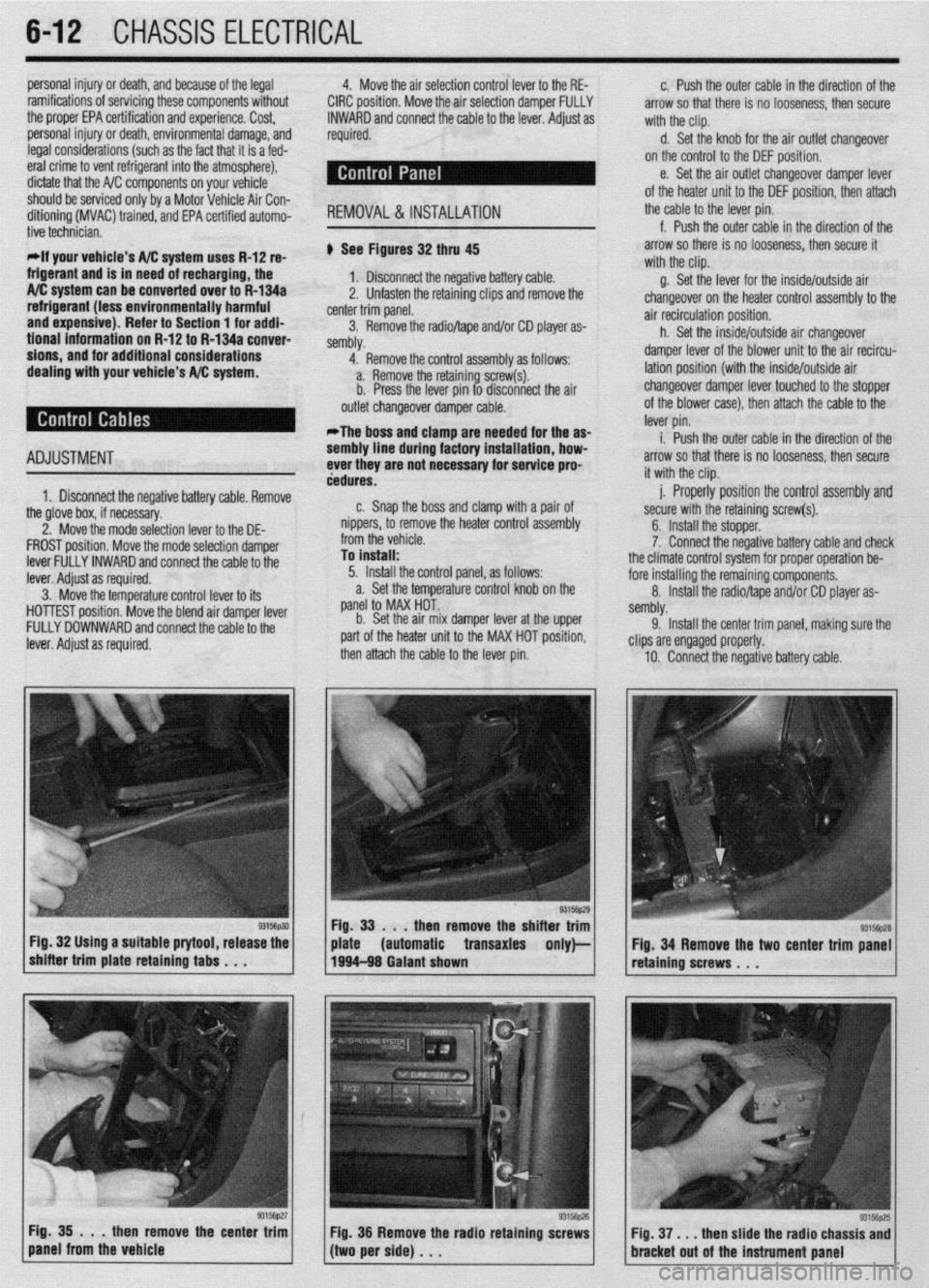
dealing with your vehicle’s A/C system. ti See Figures 32 thru 45
1. Disconnect the negative battery cable.
2, Unfasten the retaining clips and remove the
center trim panel.
3. Remove the radioltape and/or CD player as-
sembly,
4. Remove the control assembly as follows:
a. Remove the retaining screw(s).
b. Press the lever pin to disconnect the air
outlet changeover damper cable.
*The boss and clamp are needed for the as-
ADJUSTMENT
1. Disconnect the negative battery cable. Remove sembly line d
ever they are
dedures.
n Cnan i luring factory installation, how-
not necessary for service pro-
the glove box, if necessary,
2. Move the mode selection lever to the DE-
FROST position. Move the mode selection damper
lever FULLY INWARD and connect the cable to the
lever. Adiust as required.
3. M&e tht
3 temperature control lever to its
HOlli
5ST position. Move the blend air damper lever
FULL’t
’ DOWNWARD and connect the cable to the
lever. i
4djust as required. b,. dIIal, the boss and clamp with a pair of
nippers, to remove the heater control assembly
from the vehicle.
To install:
5. Install the control panel, as follows:
a. Set the temperature control knob on the
panel to MAX HOT..
b. Set the air mix damper lever at the upper
part of the heater unit to the MAX HOT position,
then attach the cable to the lever pin.
then remove the shi
Fig. 32 Using a suitable prytool, release the
automatic transaxles
93156p27 Fig. 35 . . .
then remove the center trim
panel from the vehicle
/(twiperside)... y Fig 36 Remove the radio retaining screws g. Set the lever for the inside/outside air
changeover on the heater control assemblv to the
air recirculation position.
h. Set the inside/outside air changeover
damper lever of the blower unit to the air recircu-
lation position (with the inside/outside air
changeover damper lever touched to the stopper
of the blower case), then attach the cable to the
lever pin.
i. Push the outer cable in the direction of the
arrow so that there is no looseness, then secure
it with the clip.
j. Properly position the control assembly and
secure with the retaining screw(s).
6. Install the stopper.
7. Connect the negative battery cable and check
the climate control system for proper operation be-
fore installing the remaining components.
8. Install the radio/tape and/or CD player as-
sembly.
9. Install the center trim oanel, makina sure the
clips are engaged properly. -
10. Connect the negative battery cable.
Fig. 34 Remove the two center trim panel
retaining screws . . .
Fig. 37, . . then slide the radio chassis and
bracket out of the instrument Dane1
Page 235 of 408

6-32 CHASSIS ELECTRICAL
INDEX OF WIRING DIAGRAMS
DIAGRAM 28 1990-93 Galant Wipers Chassis Schematics
DIAGRAM 29 1990-93 Galant Wipers w/ ETACS Control Unit Chassis Schematics
DIAGRAM 30 1990-93 Galant Power Door Locks Chassis Schematics
DIAGRAM 31 1990-93 Galant Power Door Locks wl ETACS Control Unit Chassis Schematics
DIAGRAM 32 1996-00 Galant Starting System Chassis Schematics
DIAGRAM 33 1994-00 Galant Charging System Chassis Schematics
DIAGRAM 34 1994-00 Galant Charging System Chassis Schematics
DIAGRAM 35 1994-00 Galant Headlights Chassis Schematics
DIAGRAM 36 1994-00 Galant Taillights Chassis Schematics
DIAGRAM 37 1994-00 Galant Brake Lights/Backup Lights/Horn Chassis Schematics
DIAGRAM 38 1994-00 Galant Turn Signal Chassis Schematics
DIAGRAM 39 1994-00 Galant Power Windows Chassis Schematics
m
DIAGRAM 40 1994-00 Galant Wipers Chassis Schematics
b
DIAGRAM 41 1994 Galant Power Door Locks w/ ETACS Control Unit Chassis Schematics
DIAGRAM 42 1994-00 Galant Power Door Locks Chassis Schematics
DIAGRAM 43 1992-00 Diamante Starting System Chassis Schematics
DIAGRAM 44 1992-00 Diamante Charging System Chassis Schematic
DIAGRAM 45 1992-93 Diamante Cabling System Chassis Schematic
DIAGRAM 46 1994-95 Diamante Cooling System Chassis Schematics
DIAGRAM 47 1996-00 Diamante Headlights Chassis Schematics
DIAGRAM 48 1992-95 Diamante Taillights/Backup Lights Chassis Schematics
DIAGRAM 49 1992-95 Diamante Turn Signal Chassis Schematics
DIAGRAM 50 1992-00 Diamante Brake Lights, Horn Chassis Schematic
DIAGRAM 51 1992-95 Diamante Power Windows Chassis Schematics
DIAGRAM 52 1992-95 Diamante Wipers Chassis Schematics
DIAGRAM 53 1992-93 Diamante Power Door Locks Chassis Schematics
Page 236 of 408
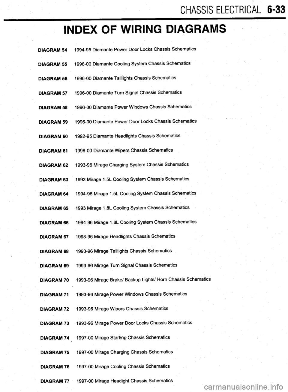
CHASSIS ELECTRlCiL 6-33
INDEX OF WIRING DIAGRAMS
DIAGRAM 54
DIAGRAM 55
DIAGRAM 56
DIAGRAM 57
DIAGRAM 58
DIAGRAM 59
DIAGRAM 60
DIAGRAM 61
DIAGRAM 62
DIAGRAM 63
DIAGRAM 64
DIAGRAM 65
DIAGRAM 66
DIAGRAM 67
DIAGRAM 68
DIAGRAM 69
DIAGRAM 70
DIAGRAM 71
DIAGRAM 72
DIAGRAM 73
DIAGRAM 74
DIAGRAM 75
DIAGRAM 76
DIAGRAM 77 1994-95 Diamante Power Door Locks Chassis Schematics
1996-00 Diamante Cooling System Chassis Schematics
1996-00 Diamante Taillights Chassis Schematics
1996-00 Diamante Turn Signal Chassis Schematics
1996-00 Diamante Power Windows Chassis Schematics
1996-00 Diamante Power Door Locks Chassis Schematics
1992-95 Diamante Headlights Chassis Schematics
1996-00 Diamante Wipers Chassis Schematics
1993-96 Mirage Charging System Chassis Schematics
1993 Mirage 1.5L Cooling System Chassis Schematics
1994-96 Mirage 1.5L Cooling System Chassis Schematics
1993 Mirage 1.8L Cooling System Chassis Schematics
1994-96 Mirage 1.8L Cooling System Chassis Schematics
1993-96 Mirage Headlights Chassis Schematics
1993-96 Mirage Taillights Chassis Schematics
1993-96 Mirage Turn Signal Chassis Schematics
1993-96 Mirage Brake/ Backup Lights/ Horn Chassis Schematics
1993-98 Mirage-Power Windows Chassis Schematics
1993-96 Mirage Wipers Chassis Schematics
1993-96 Mirage Power Door Locks Chassis Schematics
1997-00 Mirage Starting Chassis Schematics
1997-00 Mirage Charging Chassis Schematics
1997-00 Mirage Cooling Chassis Schematics
1997-00 Mirage Headight Chassis Schematics
Page 237 of 408
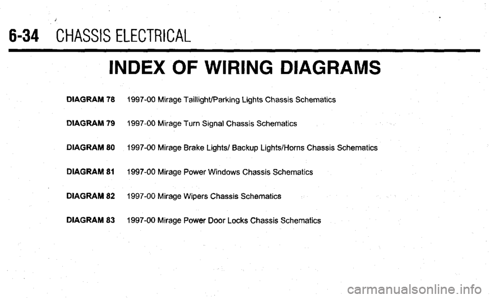
6-34 CHASSIS ELECTRICAL
INDEX OF WIRING DIAGRAMS
DIAGRAM 78 1997-00 Mirage Taillight/Parking Lights Chassis Schematics
DIAGRAM 79
1997-00 Mirage Turn Signal Chassis Schematics
DIAGRAM 80 1997-00 Mirage Brake Lights/ Backup Lights/Horns Chassis Schematics
DIAGRAM 81
1997-00 Mirage Power Windows Chassis Schematics
DIAGRAM 82 1997-00 Mirage Wipers Chassis Schematics
DIAGRAM 83 1997-00 Mirage Power Door Locks Chassis Schematics