charging MITSUBISHI ECLIPSE 1990 Service Manual
[x] Cancel search | Manufacturer: MITSUBISHI, Model Year: 1990, Model line: ECLIPSE, Model: MITSUBISHI ECLIPSE 1990Pages: 391, PDF Size: 15.27 MB
Page 88 of 391
q7 --_-.-ENGINE
- General Information9-3TECHNICAL FEATURES
HIGH PERFORMANCE AND . . .._..............1. The DOHC 16-valve engine ensures excellent intake and exhaust
FUEL ECONOMYefficiency.
2. The rocker arm is of the roller-type-cam-follower design which Iminimizes friction loss.
3. The combustion chamber is of the pentroof type with a squish
area that offers outstanding combustion efficiency.
4. The multipoint fuel injection system is electronically
controlled.5. The intake manifold is the inertia supercharging type which
improves intake efficiency and the dual-type exhaust manifold
offers good exhaust efficiency.
6. The two-coil type electronic control ignition system ensures
good ignition performance.
LOW VIBRATION AND. . . . . . ..I.................1. The hydraulic lash adjuster, together with the roller rocker arm,
LOW NOISEcontributes to reduced operating noise of the valve mechanism.
2. A cogged type belt is used to drive the camshaft.
3. The auto tensioner maintains the optimum timing belt tension.
4. The torsional damper reduces twisting vibration in the crankshaft’
to a minimum.
5. The silent shaft system reduces engine vibration and rolling
’moment to a minimum
SERVICEABILITY . . . . . . . . . . . . . . . . . . . . . . . . . . . . . . . . . . . . .1. The self-diagnosis system makes troubleshooting easier.
2. The lash adjuster eliminates the need for valve clearance
adjustment.3. The auto tensioner eliminates the need for timing belt
tension adjustment.
-.--..-. --.-
Page 123 of 391
FUEL SYSTEM -Fuel Supply and Fuel Pressure Control
FUEL-PRESSURE CONTROL VALVE
14-11To fuel
-
Fuel-pressureregulatorFuel-pressurecontrol valve
Intake-airEnginecontrol
unit
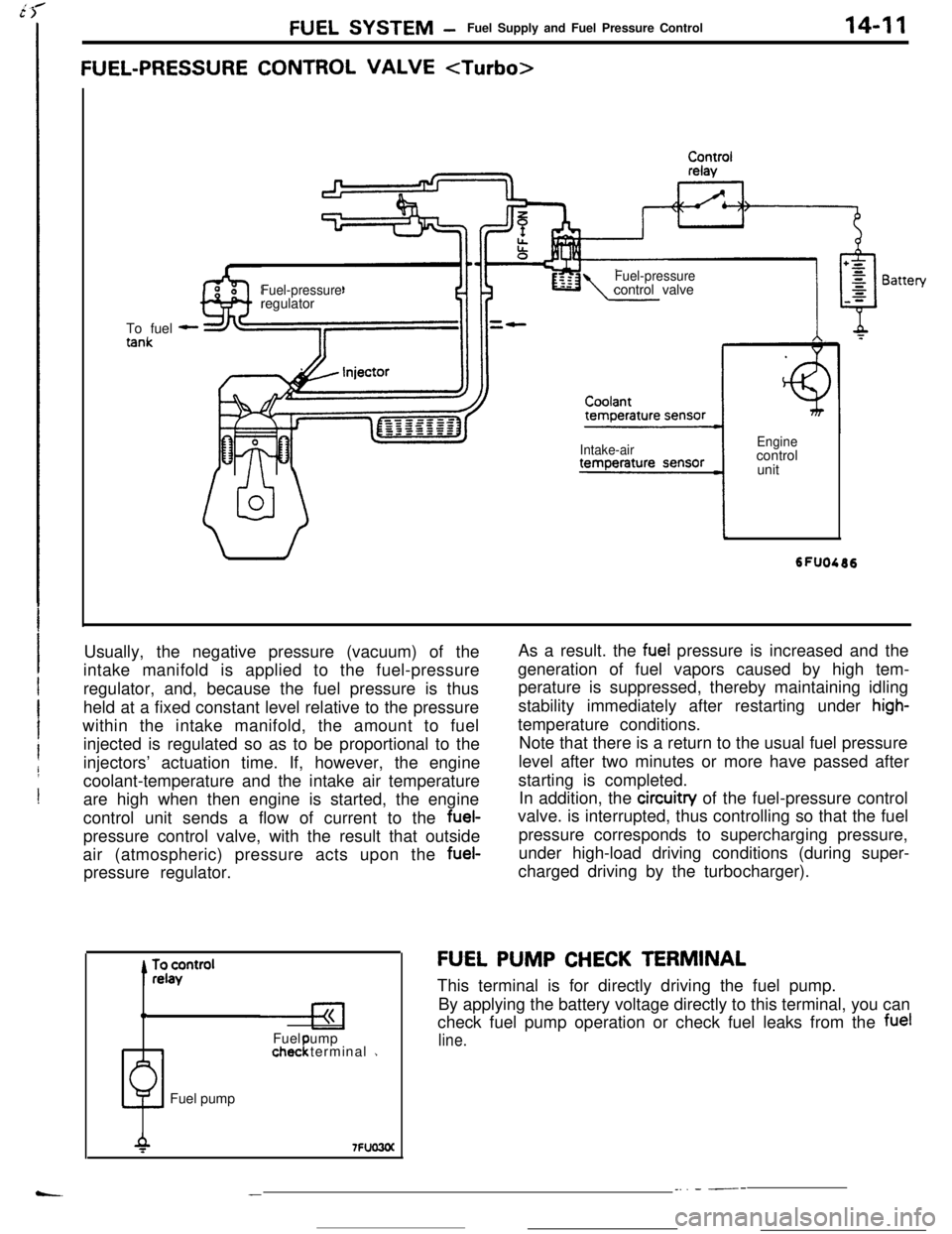
Usually, the negative pressure (vacuum) of the
intake manifold is applied to the fuel-pressure
regulator, and, because the fuel pressure is thus
held at a fixed constant level relative to the pressure
within the intake manifold, the amount to fuel
injected is regulated so as to be proportional to the
injectors’ actuation time. If, however, the engine
coolant-temperature and the intake air temperature
are high when then engine is started, the engine
control unit sends a flow of current to the fuel-
pressure control valve, with the result that outside
air (atmospheric) pressure acts upon the fuel-
pressure regulator.
0Fuel ump
1chec terminal 1!Fuel pumpAs a result. the
fuel pressure is increased and the
generation of fuel vapors caused by high tem-
perature is suppressed, thereby maintaining idling
stability immediately after restarting under
high-temperature conditions.
Note that there is a return to the usual fuel pressure
level after two minutes or more have passed after
starting is completed.
In addition, the circuitry of the fuel-pressure control
valve. is interrupted, thus controlling so that the fuel
pressure corresponds to supercharging pressure,
under high-load driving conditions (during super-
charged driving by the turbocharger).
FU,EL PUMP CHECK TERMINAL
This terminal is for directly driving the fuel pump.
By applying the battery voltage directly to this terminal, you can
check fuel pump operation or check fuel leaks from the
fuel
line.
__. - ---
Page 139 of 391
‘73.- .-_ _ .-__ .- -..- - .-----___. _____^. -._ __--.
FUEL SYSTEM- Enaine Control Unit14-27
ENGINE CONTROL UNITRI4FhAA
GENERAL DESCRIPTIONEngine control unit
~
~~:~~~~~~~~~:~~
~. . . . .. .. . . . ... . . . . ... .. :+:.:.:.:.:.:.:.~.:.~+~.
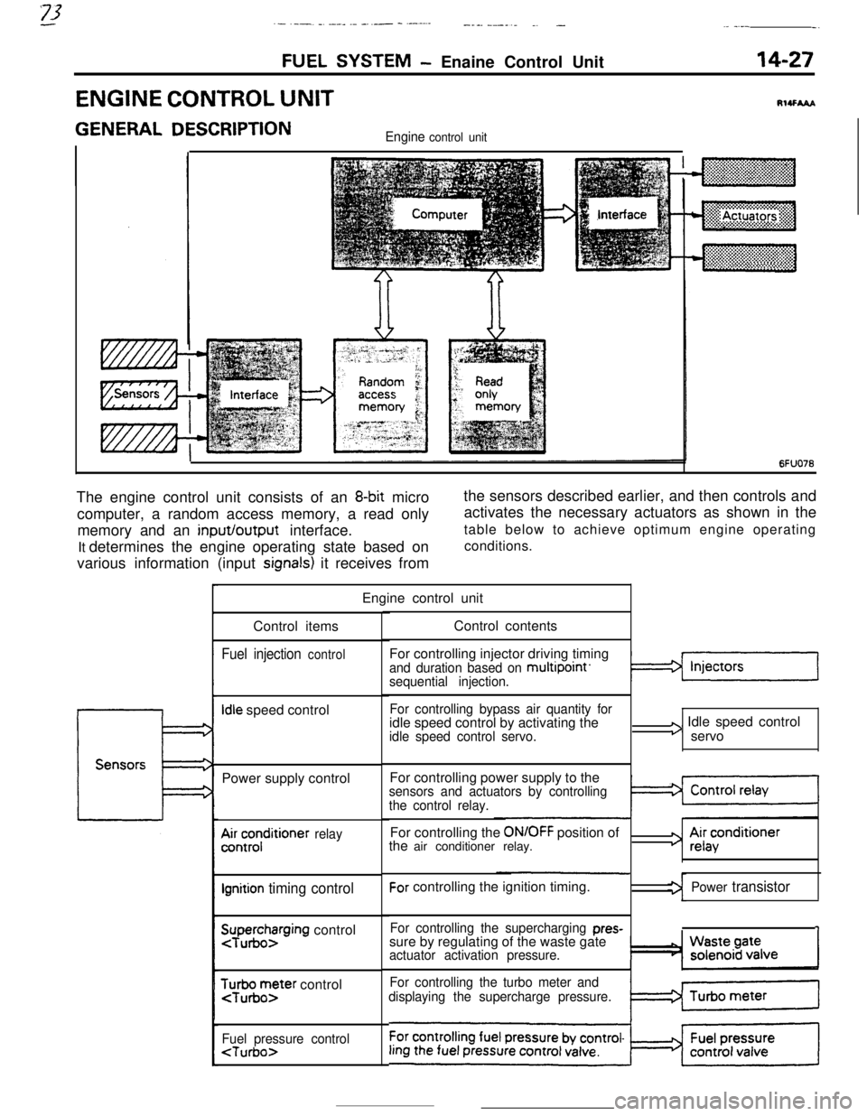
6FUO76The engine control unit consists of an
8-bit micro
computer, a random access memory, a read only
memory and an input/output interface.
It determines the engine operating state based on
various information (input
signals) it receives fromthe sensors described earlier, and then controls and
activates the necessary actuators as shown in the
table below to achieve optimum engine operating
conditions.
Engine control unit
Control items
Fuel injection control
Idle speed control
Power supply control
A&;;;ditioner relay
Ignition timing control
SuTpuegohzrging control
$r;ir;;ter control
Fuel pressure control
For controlling injector driving timing
and duration based on multipoint’sequential injection.
For controlling bypass air quantity foridle speed control by activating the
idle speed control servo.
I3 Idle speed control
servo
For controlling power supply to the
sensors and actuators by controlling
the control relay.For controlling the
ON/OFF position of
the air conditioner relay.For controlling the ignition timing.
For controlling the supercharging pres-sure by regulating of the waste gate
actuator activation pressure.
For controlling the turbo meter and
displaying the supercharge pressure.
3 Ai;acenditioner
Power transistor
1
Page 155 of 391
FUEL SYSTEM - Fuel Injection Control14-43
Time
6FUO26
Engine has started.
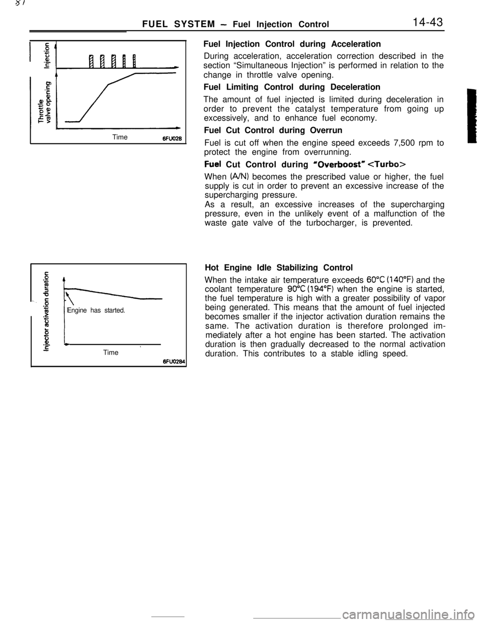
El.-*STime ’6fFuel Injection Control during Acceleration
During acceleration, acceleration correction described in the
section “Simultaneous Injection” is performed in relation to the
change in throttle valve opening.
Fuel Limiting Control during Deceleration
The amount of fuel injected is limited during deceleration in
order to prevent the catalyst temperature from going up
excessively, and to enhance fuel economy.
Fuel Cut Control during Overrun
Fuel is cut off when the engine speed exceeds 7,500 rpm to
protect the engine from overrunning.
Fuel Cut Control during ‘Overboost”
(A/N) becomes the prescribed value or higher, the fuel
supply is cut in order to prevent an excessive increase of the
supercharging pressure.
As a result, an excessive increases of the supercharging
pressure, even in the unlikely event of a malfunction of the
waste gate valve of the turbocharger, is prevented.
Hot Engine Idle Stabilizing Control
When the intake air temperature exceeds
60°C (140°F) and the
coolant temperature
90°C (194°F) when the engine is started,
the fuel temperature is high with a greater possibility of vapor
being generated. This means that the amount of fuel injected
becomes smaller if the injector activation duration remains the
same. The activation duration is therefore prolonged im-
mediately after a hot engine has been started. The activation
duration is then gradually decreased to the normal activation
duration. This contributes to a stable idling speed.
Page 168 of 391
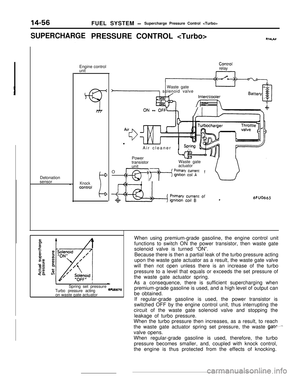
14-56FUEL SYSTEM -Supercharge Pressure Control
SUPERCHARGEPRESSURE CONTROL
sensor
lEngine control
unit
Knockcontrol
ControlrelayIntercooler
h&l --/I- h
.. .Waste gate
P solenoid valve
Air cleaner,
Power
transistorWaste gate
unit
actuatorOf
CT1 +p$?V~~~t
6FUO665
II\Spring set pressure
Turbo pressure acting5Fuo570
on waste gate actuatorWhen using premium-grade gasoline, the engine control unit
functions to switch ON the power transistor, then waste gate
solenoid valve is turned “ON”.
Because there is then a partial leak of the turbo pressure acting
upon the waste gate actuator as a result, the waste gate valve
will then not open unless there is an increase of the turbo
pressure to a level that equals or exceeds the set pressure of
the waste gate actuator spring.
As a consequence, there is sufficient supercharging when
premium-grade gasoline is used, and a high level of output can
be obtained.
If regular-grade gasoline is used, the power transistor is
switched OFF by the engine control unit, thus interrupting the
circuit of the waste gate solenoid valve and stopping the
leakage of turbo pressure.
When the turbo pressure then increases, as a result, to reach
the waste gate actuator spring set pressure, the waste
gate----valve opens.
When regular-grade gasoline is used, therefore, the turbo
pressure becomes smaller, and, coupled with knock control,
the engine is thus protected from the effects of knocking.
Page 219 of 391
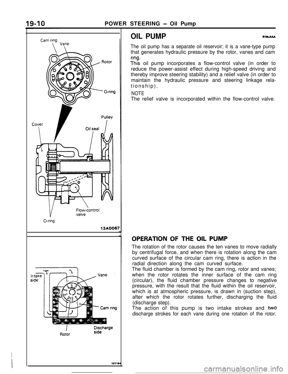
POWER STEERING - Oil Pump13A0067
Insi
OIL PUMPRlUAM
The oil pump has a separate oil reservoir; it is a vane-type pumpthat generates hydraulic pressure by the rotor, vanes and cam
y”ht oil pump incorporates a flow-control valve (in order to
reduce the power-assist effect during high-speed driving and
thereby improve steering stability) and a relief valve (in order to
maintain the hydraulic pressure and steering linkage rela-
tionship).
NOTEThe relief valve is incorporated within the flow-control valve.
OPERATION OF THE OIL PUMP
The rotation of the rotor causes the ten vanes to move radially
by centrifugal force, and when there is rotation along the cam
curved surface of the circular cam ring, there is action in the
radial direction along the cam curved surface.
The fluid chamber is formed by the cam ring, rotor and vanes;
when the rotor rotates the inner surface of the cam ring
(circular), the fluid chamber pressure changes to negative
pressure, with the result that the fluid within the oil reservoir,
which is at atmospheric pressure, is drawn in (suction step),
after which the rotor rotates further, discharging the fluid
(discharge step).
The action of this pump is two intake strokes and
two
discharge strokes for each vane during one rotation of the rotor.
Page 221 of 391
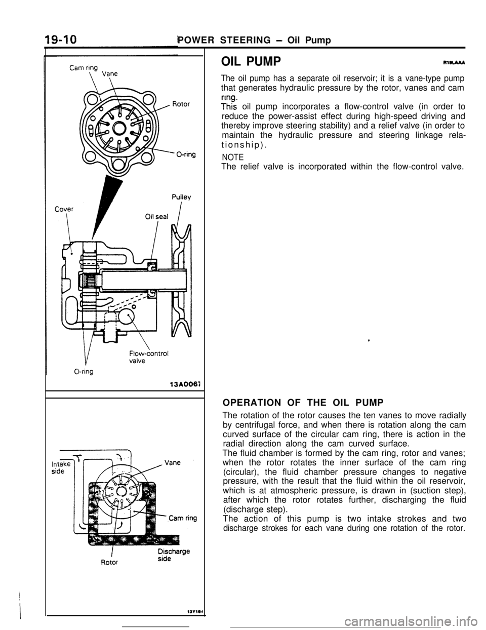
POWER STEERING - Oil Pump
OIL PUMP13A0067
Insi
m-
The oil pump has a separate oil reservoir; it is a vane-type pumpthat generates hydraulic pressure by the rotor, vanes and cam
;Inhz oil pump incorporates a flow-control valve (in order to
reduce the power-assist effect during high-speed driving and
thereby improve steering stability) and a relief valve (in order to
maintain the hydraulic pressure and steering linkage rela-
tionship).
NOTEThe relief valve is incorporated within the flow-control valve.
.OPERATION OF THE OIL PUMP
The rotation of the rotor causes the ten vanes to move radially
by centrifugal force, and when there is rotation along the cam
curved surface of the circular cam ring, there is action in the
radial direction along the cam curved surface.
The fluid chamber is formed by the cam ring, rotor and vanes;
when the rotor rotates the inner surface of the cam ring
(circular), the fluid chamber pressure changes to negative
pressure, with the result that the fluid within the oil reservoir,
which is at atmospheric pressure, is drawn in (suction step),
after which the rotor rotates further, discharging the fluid
(discharge step).
The action of this pump is two intake strokes and two
discharge strokes for each vane during one rotation of the rotor.