door lock MITSUBISHI ECLIPSE 1990 Service Manual
[x] Cancel search | Manufacturer: MITSUBISHI, Model Year: 1990, Model line: ECLIPSE, Model: MITSUBISHI ECLIPSE 1990Pages: 391, PDF Size: 15.27 MB
Page 12 of 391
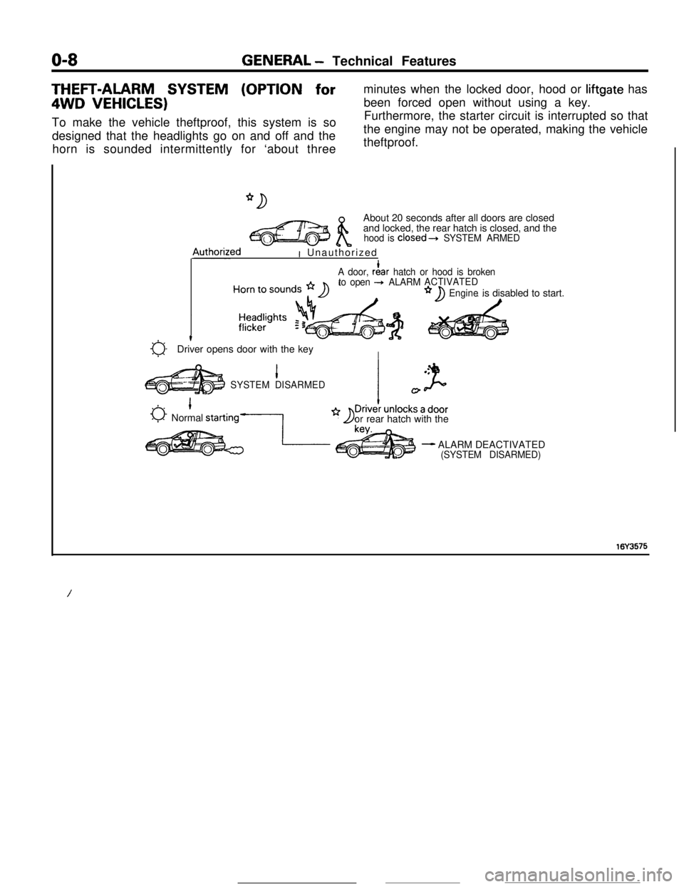
O-8GENERAL - Technical FeaturesTHEFT-ALARM SYSTEM (OPTION for4WD
VEHICLES)To make the vehicle theftproof, this system is so
designed that the headlights go on and off and the
horn is sounded intermittently for ‘about threeminutes when the locked door, hood or liftgate has
been forced open without using a key.
Furthermore, the starter circuit is interrupted so that
the engine may not be operated, making the vehicle
theftproof.
About 20 seconds after all doors are closed
and locked, the rear hatch is closed, and the
hood is closed---t SYSTEM ARMED4uthorized
I Unauthorized
A door, rf!ar hatch or hood is broken
to open + ALARMACTIVATED
Engineis disabled to start.
a-t
Driver opens door with the keyI
1SYSTEM DISARMED
0 1Normal starting-1
I
orrear hatch with the
- ALARM DEACTIVATED(SYSTEM DISARMED)
16Y3575
/
Page 16 of 391
o-12GENERAL - Vehicle Identification
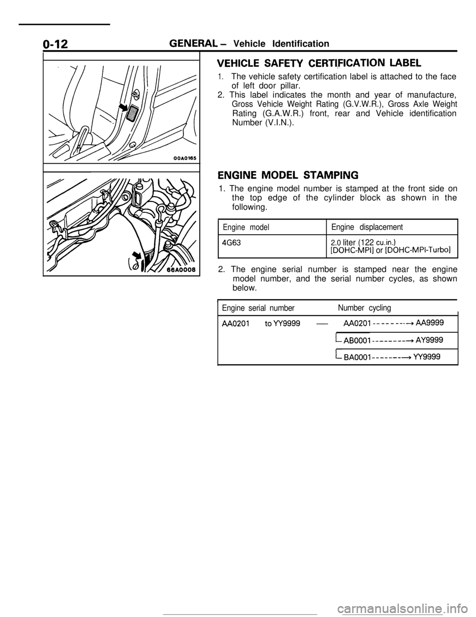
VEHICLE SAFETY CERTI,FICATION LABEL
1.The vehicle safety certification label is attached to the face
of left door pillar.
2. This label indicates the month and year of manufacture,
Gross Vehicle Weight Rating (G.V.W.R.), Gross Axle WeightRating (G.A.W.R.) front, rear and Vehicle identification
Number (V.I.N.).
ENGINE MODEL STAMPING
1. The engine model number is stamped at the front side on
the top edge of the cylinder block as shown in the
following.
Engine model
4663
Engine displacement
2.0 liter (122 cu.in.)[DOHC-MPI] or [DOHC-MPI-Turbo12. The engine serial number is stamped near the engine
model number, and the serial number cycles, as shown
below.
Engine serial numberNumber cycling
AA0201 toYY9999 -AAo201--------hAA
LAB0001 --------+ AY9999
L BAOOOl-------+ YY9999
Page 55 of 391
ELECTRICAL - Fuses8-3q
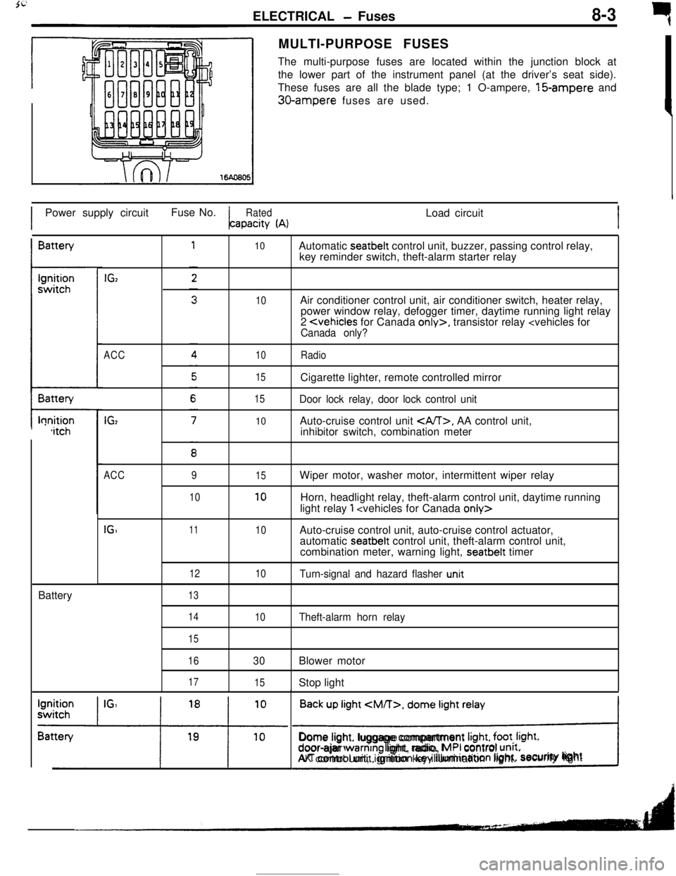
rMULTI-PURPOSE FUSES
The multi-purpose fuses are located within the junction block at
the lower part of the instrument panel (at the driver’s seat side).
These fuses are all the blade type; 1 O-ampere, 15-ampere and
30-ampere fuses are used.
IPower supply circuitFuse No.
RatedLoad circuitapacity
(A)IBattery
t-lonition,itchBattery
IGz
ACC
IG,
10
10
10
15
15
10Automatic seatbelt control unit, buzzer, passing control relay,
key reminder switch, theft-alarm starter relay
Air conditioner control unit, air conditioner switch, heater relay,
power window relay, defogger timer, daytime running light relay
2
Door lock relay, door lock control unitAuto-cruise control unit
, AA control unit,
inhibitor switch, combination meter
ACC
IGI9
1011
12
1315
10
10
10Wiper motor, washer motor, intermittent wiper relay
Horn, headlight relay, theft-alarm control unit, daytime running
light relay
1
automatic seatbelt control unit, theft-alarm control unit,
combination meter, warning light, seatbelt timer
Turn-signal and hazard flasher u.nit
14
15
16
17
10Theft-alarm horn relay
30Blower motor
15Stop light
Back up light
CM/T>, dome light relay
!Dome light. luggage compartment
Irght, foot. Irght.door-ajar warntng light, radio, MPI control unrt.AK control unit, ignition key illumination light.security lightI
Page 65 of 391
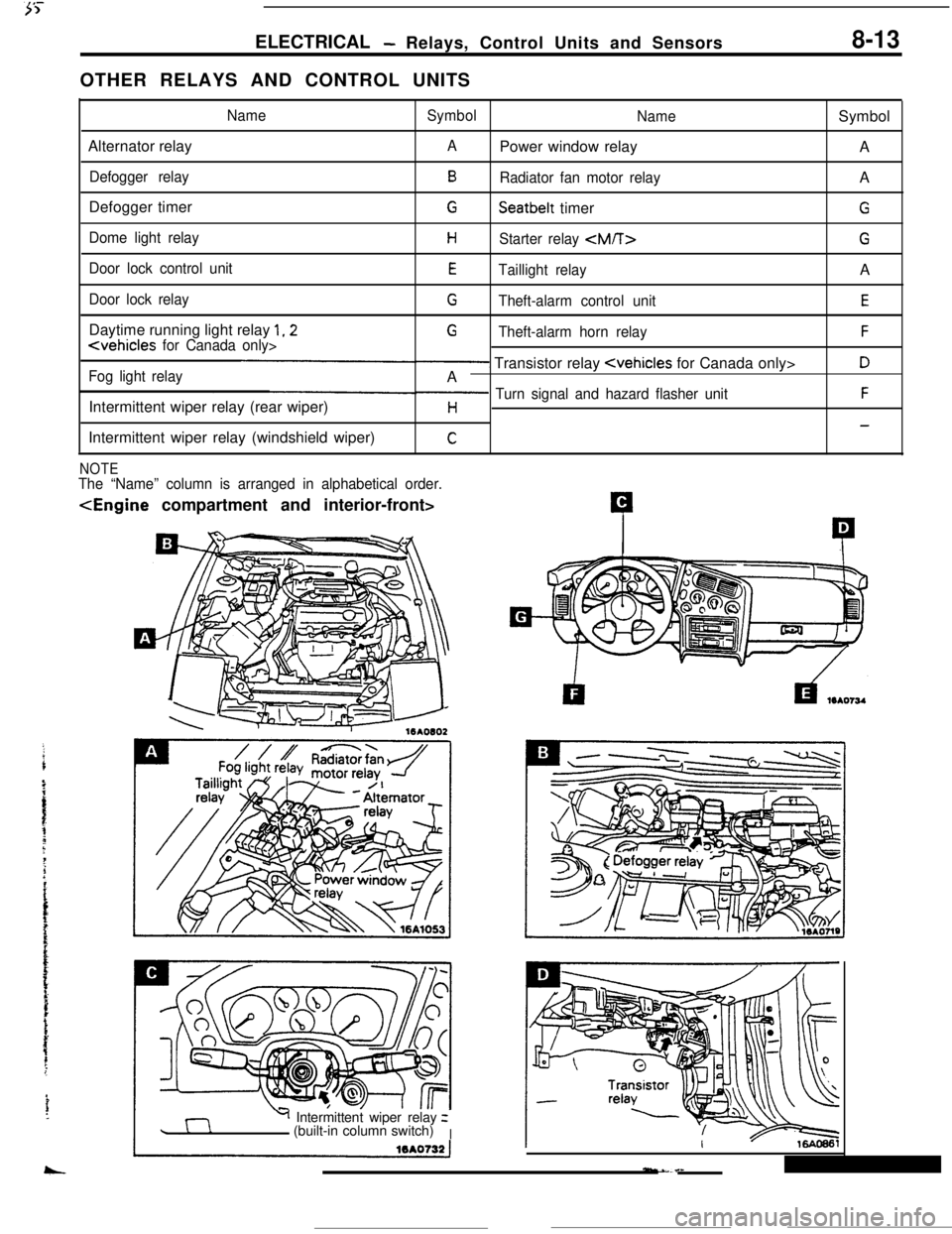
ELECTRICAL- Relays, Control Units and Sensors8-13OTHER RELAYS AND CONTROL UNITS
NameSymbol
NameSymbol
Alternator relay
APower window relay
A
Defogger relayBRadiator fan motor relayA
Defogger timer
GSeatbelt timerG
Dome light relayHStarter relay
Door lock control unitETaillight relayA
Door lock relayGTheft-alarm control unitEDaytime running light relay
1,2G
Fog light relay- Transistor relay
Intermittent wiper relay (rear wiper)
p Turn signal and hazard flasher unitFH-Intermittent wiper relay (windshield wiper)
C
NOTEThe “Name” column is arranged in alphabetical order.
Y Intermittent wiper relayz
(built-in column switch)
I
Page 84 of 391
8-32ELECTRICAL - Theft-alarm System
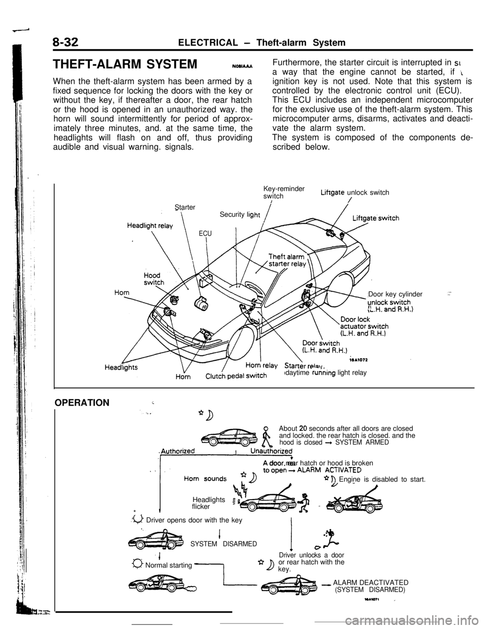
THEFT-ALARM SYSTEM
NOOIAAAWhen the theft-alarm system has been armed by a
fixed sequence for locking the doors with the key or
without the key, if thereafter a door, the rear hatch
or the hood is opened in an unauthorized way. the
horn will sound intermittently for period of approx-
imately three minutes, and. at the same time, the
headlights will flash on and off, thus providing
audible and visual warning. signals.Furthermore, the starter circuit is interrupted in SIa way that the engine cannot be started, if
‘Lignition key is not used. Note that this system is
controlled by the electronic control unit (ECU).
This ECU includes an independent microcomputer
for the exclusive use of the theft-alarm system. This
microcomputer arms, disarms, activates and deacti-
vate the alarm system.
The system is composed of the components de-
scribed below.
Key-reminder
switchLiftgate unlock switch
!/Starter
Door key cylinder
”daytime running light relay Security
lig
ECU
I
HornOPERATION
iAbout
20 seconds after all doors are closed
and locked. the rear hatch is closed. and the
hood is closed + SYSTEM ARMED
. .‘11A door rear hatch or hood is brokenALARM ACT,“ATED
* n Engine is disabled to start.
Headlights
Iflicker
*.
.u Driver opens door with the key
I.l .
SYSTEM DISARMEDI J-0
-IDriver unlocks a door
0 Normal starting -1or rear hatch with the*D key.
- ALARM DEACTIVATED(SYSTEM DISARMED)
Page 85 of 391
ELECTRICAL - Theft-alarm System8-33ARMING THE SYSTEM
After the following procedures have been completed, the SECURITY light illuminates for about 20 seconds,
and when illumination stops, the system is armed.
(1) Pull out the ignition key from the key cylinder.
(2) Open a door. (The other door is closed.)
(3) Lock the door with the key or the
keyless-locking method.
(The central door locking system will then function to lock all doors.)
NOTE(1) The system is set regardless of whether the hood and liftgate are open or
closed, and is armed as
soon as the light goes out.
(2) Even after the system has been armed, if the key is used to open the liftgate, the system will not be
activated; when the liftgate is then
closed, moreover, the system will be armed.
DISARMING THE SYSTEM
(1) The system will be disarmed if the key is used to unlock a door.
(2) If the system is armed while the driver is still in the vehicle, the system can be disarmed by inserting the
ignition key and turning it to the ACC or ON position.
(3) If the door lock is unlocked while closing the door or the door is ajar.
(4) If the door is unfastened while the SECURITY light illuminates.
ACTIVATING THE ALARM
(1) if an attempt is made to open a door, the liftgate or the hood, without using the key, while the system is
armed, the horn will sound intermittently and the headlights will flash on and off for approximately
three,
minutes.Furthermore, the starter circuit is interrupted at this time also, making starting of the engine impossible.
(2) if a further attempt at *forcible entry is made after the first three-minute alarm has finished, the
three-minute alarm will be activated again.
DEACTIVATING THE ALARM
(1) To deactivate the alarm, insert the key into the door’s key cylinder and turn the key.
(2) The alarm is deactivated and the system is disarmed when the iiftgate is unlocked with the key.
CHECKING THE SYSTEM OPERATION
The activation/operation of the system can be checked by following the steps below.
(1) Turn the ignition key to the ON position and then use the power-window switch to fully open the window
at the driver’s seat side.
(2) Turn the ignition key to the LOCK position and then remove the key from the ignition.
(3) Open only the driver’s door, and close all the other doors, as well as the hood and the rear hatch.
(4) Lock the driver’s door by the key or the
keyless-locking method.
(5) All doors will then be
locked, and the SECURITY light (within the combination meter) will illuminate; check
to be sure that illumination stops in about 20 seconds.
(6) After about two seconds have passed after the SECURITY light illumination stopped, reach through the
window of the driver’s door, pull up the lock lever to unlock the door, and then open the door.
(7) Check to be sure that, when the door is opened, the horn starts sounding and the headlights flash on and
Off.
(8) To stop the alarm, insert the key into the door’s key cylinder and turn the key.
!?iEeck the alarm for the opening of the liftgate or hood open the liftgate (or the hood) by using the
remote liftgate release lever (or the hood release lever),
located at the driver’s seat side either before the
alarm is activated by the opening of a door, or after the finish of the first three-minute alarm.
Page 337 of 391
23-20BODY - Central Door LocksCENTRAL DOOR LOCKS
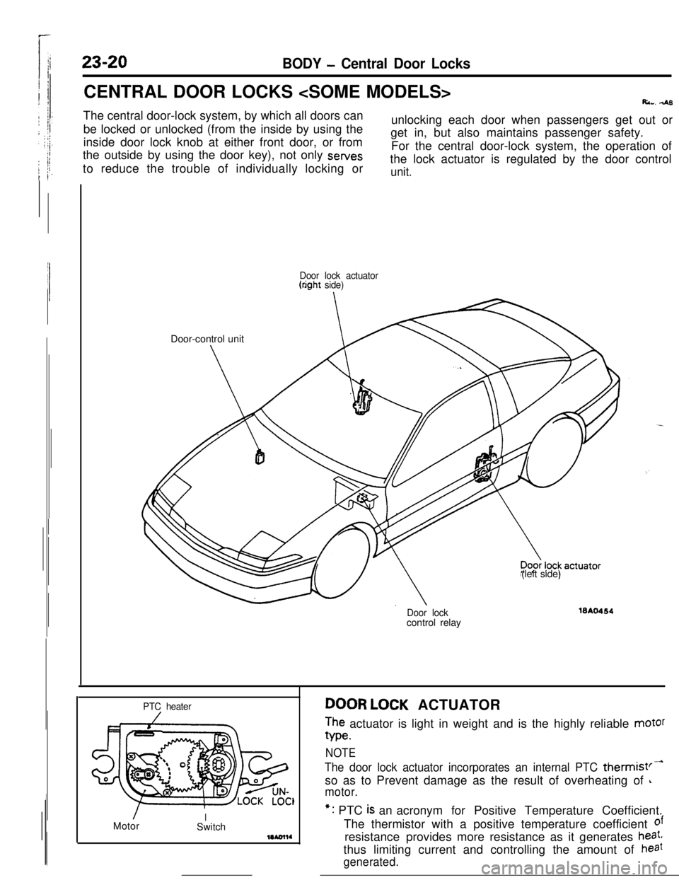
Ri... 4sThe central door-lock system, by which all doors can
be locked or unlocked (from the inside by using the
inside door lock knob at either front door, or from
the outside by using the door key), not only sewes
to reduce the trouble of individually locking orunlocking each door when passengers get out or
get in, but also maintains passenger safety.
For the central door-lock system, the operation of
the lock actuator is regulated by the door control
unit.
Door lock actuator(right side)Door-control unit
(left side)
Door lockcontrol relay16A0464
PTC heater
/MotorISwitchDOOR LOCK ACTUATOR
The actuator is light in weight and is the highly reliable motor
We.
NOTE
The door lock actuator incorporates an internal PTC thermist’-so as to Prevent damage as the result of overheating of
L
motor.*: PTC
is an acronym for Positive Temperature Coefficient.
The thermistor with a positive temperature coefficient
ofresistance provides more resistance as it generates
heat,thus limiting current and controlling the amount of
haat
generated.
Page 338 of 391
BODY - Central Door Locks23-21
IBattery
1IJDoor lock 4Door lockactuator t(left side)actuator
(right side) -Battery
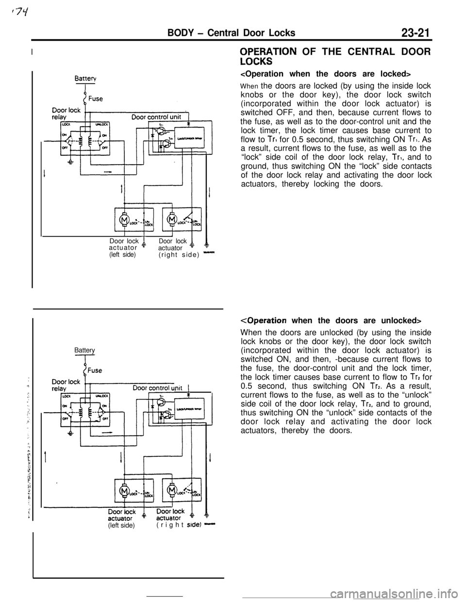
Init !,WF%;$TlON OF THE CENTRAL DOOR
When the doors are locked (by using the inside lock
knobs or the door key), the door lock switch
(incorporated within the door lock actuator) is
switched OFF, and then, because current flows to
the fuse, as well as to the door-control unit and the
lock timer, the lock timer causes base current to
flow to
TrI for 0.5 second, thus switching ON Tr,. As
a result, current flows to the fuse, as well as to the
“lock” side coil of the door lock relay,
Tr,, and to
ground, thus switching ON the “lock” side contacts
of the door lock relay and activating the door lock
actuators, thereby locking the doors.
When the doors are unlocked (by using the inside
lock knobs or the door key), the door lock switch
(incorporated within the door lock actuator) is
switched ON, and then, -because current flows to
the fuse, the door-control unit and the lock timer,
the lock timer causes base current to flow to
Tr? for
0.5 second, thus switching ON
Tr7. As a result,
current flows to the fuse, as well as to the “unlock”
side coil of the door lock relay,
Trp, and to ground,
thus switching ON the “unlock” side contacts of the
door lock relay and activating the door lock
actuators, thereby the doors.
(left side)(right
side) -
Page 339 of 391
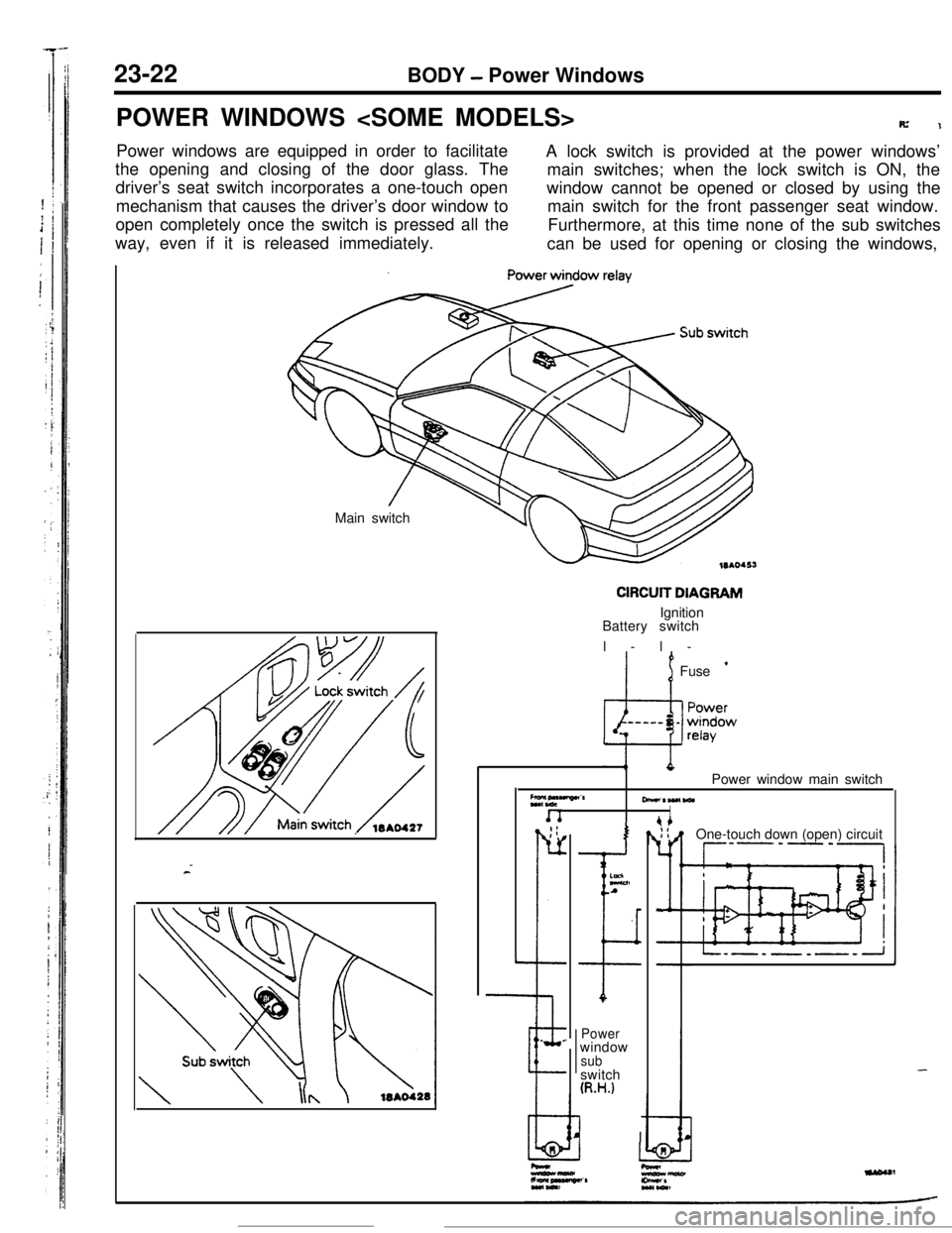
23-22BODY - Power Windows
POWER WINDOWS
R’1Power windows are equipped in order to facilitate
A lock switch is provided at the power windows’
the opening and closing of the door glass. The
main switches; when the lock switch is ON, the
driver’s seat switch incorporates a one-touch open
mechanism that causes the driver’s door window towindow cannot be opened or closed by using the
main switch for the front passenger seat window.
open completely once the switch is pressed all the
way, even if it is released immediately.Furthermore, at this time none of the sub switches
can be used for opening or closing the windows,
Main switch
CIRCUIT DIAGRAMIgnition
Battery switch
l-l-
’ 1Fuse ’
Z*,“““”CrPower window main switch
-*W(WlI. _;:
r-
L
--e.
.
I
ELnA
I
Powerwindow
subswitch
(R.H.)
I IOne-touch down (open) circuit
--P’-‘-,
-
Page 348 of 391
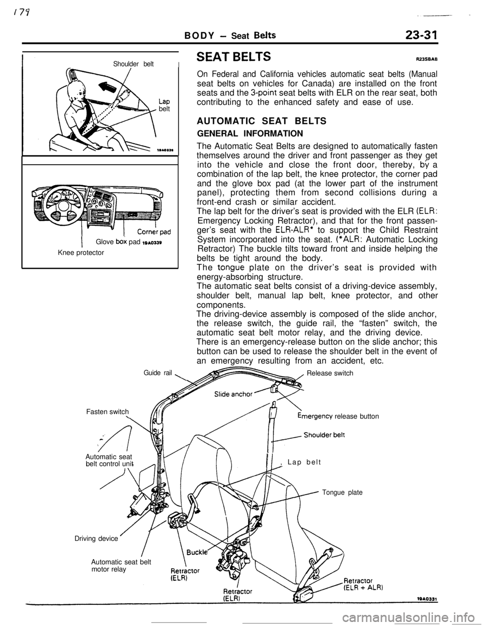
BODY - Seat Belts
._-- -
23-31
Shoulder beltI
Lapbelt
IGlove box pad toasty
Knee protector
Guide rail\Fasten switch
\
SEAT BELTSRZ3SBAS
On Federal and California vehicles automatic seat belts (Manualseat belts on vehicles for Canada) are installed on the front
seats and the
3-point seat belts with ELR on the rear seat, both
contributing to the enhanced safety and ease of use.
AUTOMATIC SEAT BELTS
GENERAL INFORMATION
The Automatic Seat Belts are designed to automatically fasten
themselves around the driver and front passenger as they get
into the vehicle and close the front door, thereby,
by a
combination of the lap belt, the knee protector, the corner pad
and the glove box pad (at the lower part of the instrument
panel), protecting them from second collisions during a
front-end crash or similar accident.
The lap belt for the driver’s seat is provided with the ELR
(ELR:Emergency Locking Retractor), and that for the front passen-
ger’s seat with the
ELR-ALR” to support the Child Restraint
System incorporated into the seat. (“ALR: Automatic Locking
Retractor) The buckle tilts toward front and inside helping the
belts be tight around the body.
The
tongue plate on the driver’s seat is provided with
energy-absorbing structure.
The automatic seat belts consist of a driving-device assembly,
shoulder belt, manual lap belt, knee protector, and other
components.
The driving-device assembly is composed of the slide anchor,
the release switch, the guide rail, the “fasten” switch, the
automatic seat belt motor relay, and the driving device.
There is an emergency-release button on the slide anchor; this
button can be used to release the shoulder belt in the event of
an emergency resulting from an accident, etc.
Release switchmergency
release button
Automatic seat
belt control unit
PI, Lap belt
Tongue plateDriving device
Automatic seat belt
motor relay