gas type MITSUBISHI ECLIPSE 1990 Service Manual
[x] Cancel search | Manufacturer: MITSUBISHI, Model Year: 1990, Model line: ECLIPSE, Model: MITSUBISHI ECLIPSE 1990Pages: 391, PDF Size: 15.27 MB
Page 87 of 391
=--Y
jl
1 /
i "
_. ---“._ _ _ ._ ..-..+_LI_y_--- -
9-2ENGINE- General Information
GENERAL INFORMATION
MAJOR
SPEClFlCATiONS
Row- -
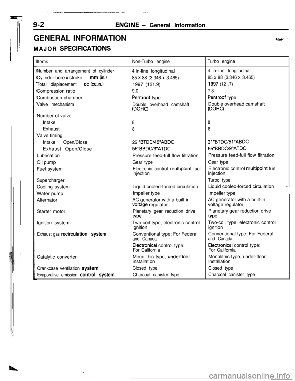
Items
Number and arrangement of cylinderCylinder bore x stroke
mm (in.)
Total displacementcc (cu.in.1Compression ratio
Combustion chamber
Valve mechanismNumber of valve
Intake
Exhaust
Valve timing
IntakeOpen/CloseExhaust Open/Close
Lubrication
Oil pump
Fuel system
SuperchargerCooling system
Water pump
Alternator
Starter motor
Ignition system
Exhaust gas recirculation systemCatalytic converter
Crankcase ventilation system
Evaporative emission control system
Non-Turbo engineTurbo engine4 in-line, longitudinal
4 in-line, longitudinal
85 x
88 (3.346 x 3.465)85 x 88 (3.346 x 3.465)1997 (121.9)
1997 (121.7)
9.07.8
Pentroof typePentroof type
Double overhead camshaftDouble overhead camshaft
(DOHC)(DOHC)
88
88
26 “BTDU46”ABDC21”BTDC/Sl”ABDC56BBDUS”ATDC55”BBDUS”ATDC
Pressure feed-full flow filtrationPressure feed-full flow filtration
Gear typeGear type
Electronic control multipoint
fuelElectronic control multipoint fuel
injectioninjection
Turbo typeLiquid cooled-forced circulationLiquid cooled-forced circulation
-Impeller typeImpeller type
AC generator with a built-involtage regulatorAC generator with a built-in
voltage regulator
Planetary gear reduction drivePlanetary gear reduction drivetype
Two-coil type, electronic controlTwo-coil type, electronic control
ignitionignition
Conventional type: For FederalConventional type: For Federal
and Canadaand Canada
Electronical control type:Electronical control type:
For CaliforniaFor CaliforniaMonolithic type,
under-floorMonolithic type, under-floor
installationinstallation
Closed typeClosed type
Charcoal canister typeCharcoal canister type
I
Page 374 of 391
25-2EMISSION CONTROL SYSTEMS - General Information
GENERAL INFORMATION
There are three sources of vehicle exhaust emis-
sions generated: the exhaust gases resulting from
combustion, the blow-by gases generated within
the crankcase, and the evaporative emissions
generated from the fuel tank and other components
of the fuel line.
The emissions-control system, which is designed to
control the discharge of these exhaust gases into
the atmosphere, is composed of the following
system components.
(1) Exhaust emission control system
(2) Crankcase emission control system
(3) Evaporative emission control system
R258A’The exhaust emissions-control system reduces the
amount of carbon monoxide, hydro carbon and
oxides of nitrogen in the exhaust gases by adding
the exhaust gas recirculation device and the cataly-
tic converter to fundamental improvements such as
improvement of the combustion chamber and the
camshaft, as well as other improvements to the
engine such as feedback control of the air/fuel ratio
by the electronically controlled fuel injection sys-
tem.
The crankcase emissions-control system is a closed
type so that blow-by gases are not discharged out to
the atmosphere. The evaporative emissions-control
system is the canister type; vapors that are gener-
ated within the fuel tank are introduced into the
intake manifold and are combusted so that they are
not emitted out to the atmosphere.
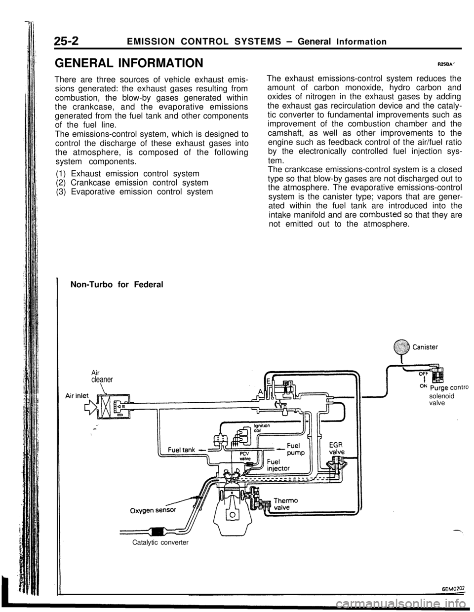
Non-Turbo for Federal
Air
cleaner
\solenoid
valve
Catalytic converter
:
0
$2:) Canister:.:
Page 376 of 391
--.
25-2EMISSION CONTROL SYSTEMS - General Information
GENERAL INFORMATION
There are three sources of vehicle exhaust emis-
sions generated: the exhaust gases resulting from
combustion, the blow-by gases generated within
the crankcase, and the evaporative emissions
generated from the fuel tank and other components
of the fuel line.
The emissions-control system, which is designed to
control the discharge of these exhaust gases into
the atmosphere,is composed of the following
system components.
(1) Exhaust emission control system
(2) Crankcase emission control system
(3) Evaporative emission control system
RZSBAThe exhaust emissions-control system reduces the
amount of carbon monoxide, hydro carbon and
oxides of nitrogen in the exhaust gases by adding
the exhaust gas recirculation device and the cataly-
tic converter to fundamental improvements such as
improvement of the combustion chamber and the
camshaft, as well as other improvements to the
engine such as feedback control of the air/fuel ratio
by the electronically controlled fuel injection sys-
tem.
The crankcase emissions-control system is a closed
type so that blow-by gases are not discharged out to
the atmosphere. The evaporative emissions-control
system is the canister type; vapors that are gener-
ated within the fuel tank are introduced into the
intake manifold and are combusted so that they are
not emitted out to the atmosphere.
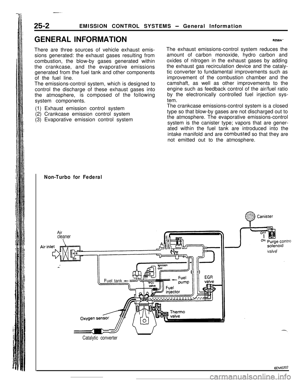
Non-Turbo for Federal
.;. :
0
.%??? CanisterAir
cleaner
\valveOxygenFuel tank
-a I”’ ,T
sensr’
Catalytic converter
6EMO?O2
Page 382 of 391
25-8EMISSION CONTROL SYSTEMS- Exhaust Gas Recirculation (EGR) System
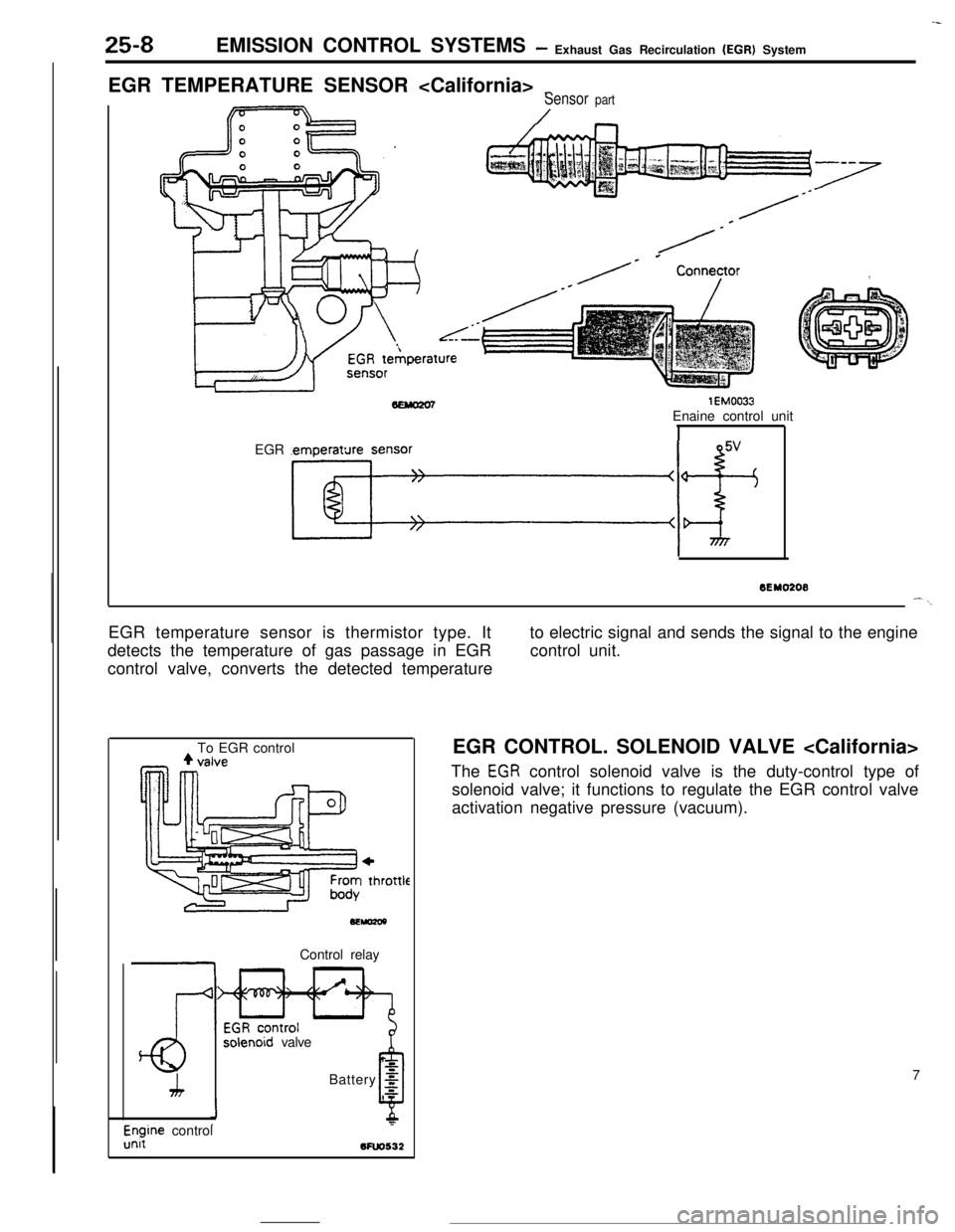
EGR TEMPERATURE SENSOR
_Sensor part
/
/-
/* * Conneyor,
lEM0033Enaine control unit
EGR temperature sensor
Kf+
--
6EY0208--\EGR temperature sensor is thermistor type. It
detects the temperature of gas passage in EGR
control valve, converts the detected temperatureto electric signal and sends the signal to the engine
control unit.
To EGR control
+I thl
.ottleControl relay
solenoid valve
h
LBattery
g
0s
l$ine control5FW532EGR CONTROL. SOLENOID VALVE
The
EGR control solenoid valve is the duty-control type of
solenoid valve; it functions to regulate the EGR control valve
activation negative pressure (vacuum).
7
Page 383 of 391
---- .~ _ _EMISSION CONTROL SYSTEMS
- Catalytic Converter I Air-fuel Mixture Ratio Control System25-9
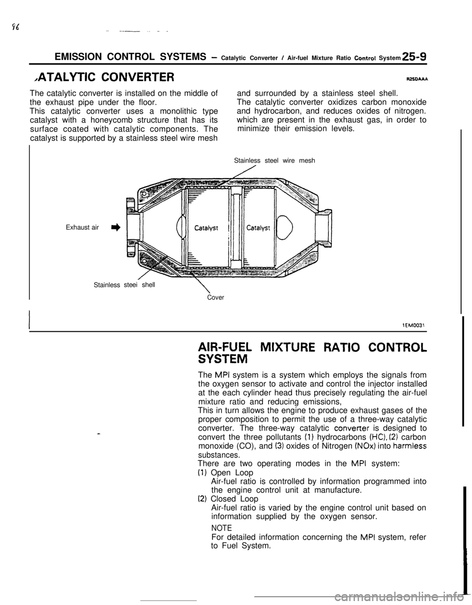
,ATALYTlC CONVERTERRZXIAAAThe catalytic converter is installed on the middle ofand surrounded by a stainless steel shell.
the exhaust pipe under the floor.The catalytic converter oxidizes carbon monoxide
This catalytic converter uses a monolithic type
catalyst with a honeycomb structure that has itsand hydrocarbon, and reduces oxides of nitrogen.
surface coated with catalytic components. Thewhich are present in the exhaust gas, in order to
minimize their emission levels.
catalyst is supported by a stainless steel wire mesh
Exhaust air
3Stainlesssteei shell
\CoverStainless steel wire mesh
lEM0031
AIR-FUEL MIXTURE RATIO CONTROL
SYSTEMThe
MPI system is a system which employs the signals from
the oxygen sensor to activate and control the injector installed
at the each cylinder head thus precisely regulating the air-fuel
mixture ratio and reducing emissions,
This in turn allows the engine to produce exhaust gases of the
proper composition to permit the use of a three-way catalytic
converter. The three-way catalytic converter is designed to
convert the three pollutants
(1) hydrocarbons (HC), (2) carbon
monoxide (CO), and
(3) oxides of Nitrogen (NOx) into harmiess
substances.There are two operating modes in the
MPI system:
(1) Open Loop
Air-fuel ratio is controlled by information programmed into
the engine control unit at manufacture.
(2) Closed Loop
Air-fuel ratio is varied by the engine control unit based on
information supplied by the oxygen sensor.
NOTEFor detailed information concerning the
MPI system, refer
to Fuel System.
Page 384 of 391
25-10EMISSION CONTROL SYSTEMS - Crankcase Ventilation Svstem-
CRANKCASE VENTILATION SYS-fUSFAAA,r
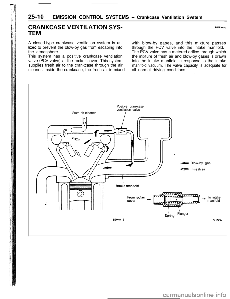
TEMA closed-type crankcase ventilation system is
uti-with blow-by gases, and this mixture passes
lized to prevent the blow-by gas from escaping into
through the PCV valve into the intake manifold.
the atmosphere.The PCV valve has a metered orifice through which
This system has a positive crankcase ventilation
the mixture of fresh air and blow-by gases is drawn
valve
(PCV valve) at the rocker cover. This system
into the intake manifold in response to the intake
supplies fresh air to the crankcase through the air
manifold vacuum. The valve capacity is adequate forcleaner. Inside the crankcase, the fresh air is mixed
all normal driving conditions.
From air cleanerPositive crankcaseventilation valve
a Blow-by gas
a Freshair
To intakemanifold
6EM0115
SiringPlunger
7EMOOZi