stop start MITSUBISHI ECLIPSE 1990 Service Manual
[x] Cancel search | Manufacturer: MITSUBISHI, Model Year: 1990, Model line: ECLIPSE, Model: MITSUBISHI ECLIPSE 1990Pages: 391, PDF Size: 15.27 MB
Page 55 of 391
ELECTRICAL - Fuses8-3q
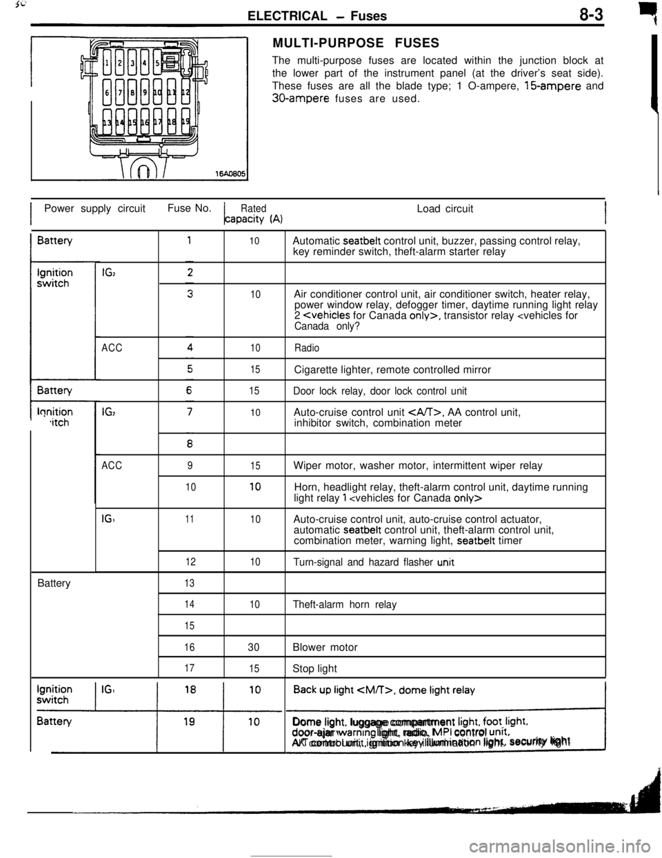
rMULTI-PURPOSE FUSES
The multi-purpose fuses are located within the junction block at
the lower part of the instrument panel (at the driver’s seat side).
These fuses are all the blade type; 1 O-ampere, 15-ampere and
30-ampere fuses are used.
IPower supply circuitFuse No.
RatedLoad circuitapacity
(A)IBattery
t-lonition,itchBattery
IGz
ACC
IG,
10
10
10
15
15
10Automatic seatbelt control unit, buzzer, passing control relay,
key reminder switch, theft-alarm starter relay
Air conditioner control unit, air conditioner switch, heater relay,
power window relay, defogger timer, daytime running light relay
2
Door lock relay, door lock control unitAuto-cruise control unit
, AA control unit,
inhibitor switch, combination meter
ACC
IGI9
1011
12
1315
10
10
10Wiper motor, washer motor, intermittent wiper relay
Horn, headlight relay, theft-alarm control unit, daytime running
light relay
1
automatic seatbelt control unit, theft-alarm control unit,
combination meter, warning light, seatbelt timer
Turn-signal and hazard flasher u.nit
14
15
16
17
10Theft-alarm horn relay
30Blower motor
15Stop light
Back up light
CM/T>, dome light relay
!Dome light. luggage compartment
Irght, foot. Irght.door-ajar warntng light, radio, MPI control unrt.AK control unit, ignition key illumination light.security lightI
Page 70 of 391
8-18ELECTRICAL - Lighting
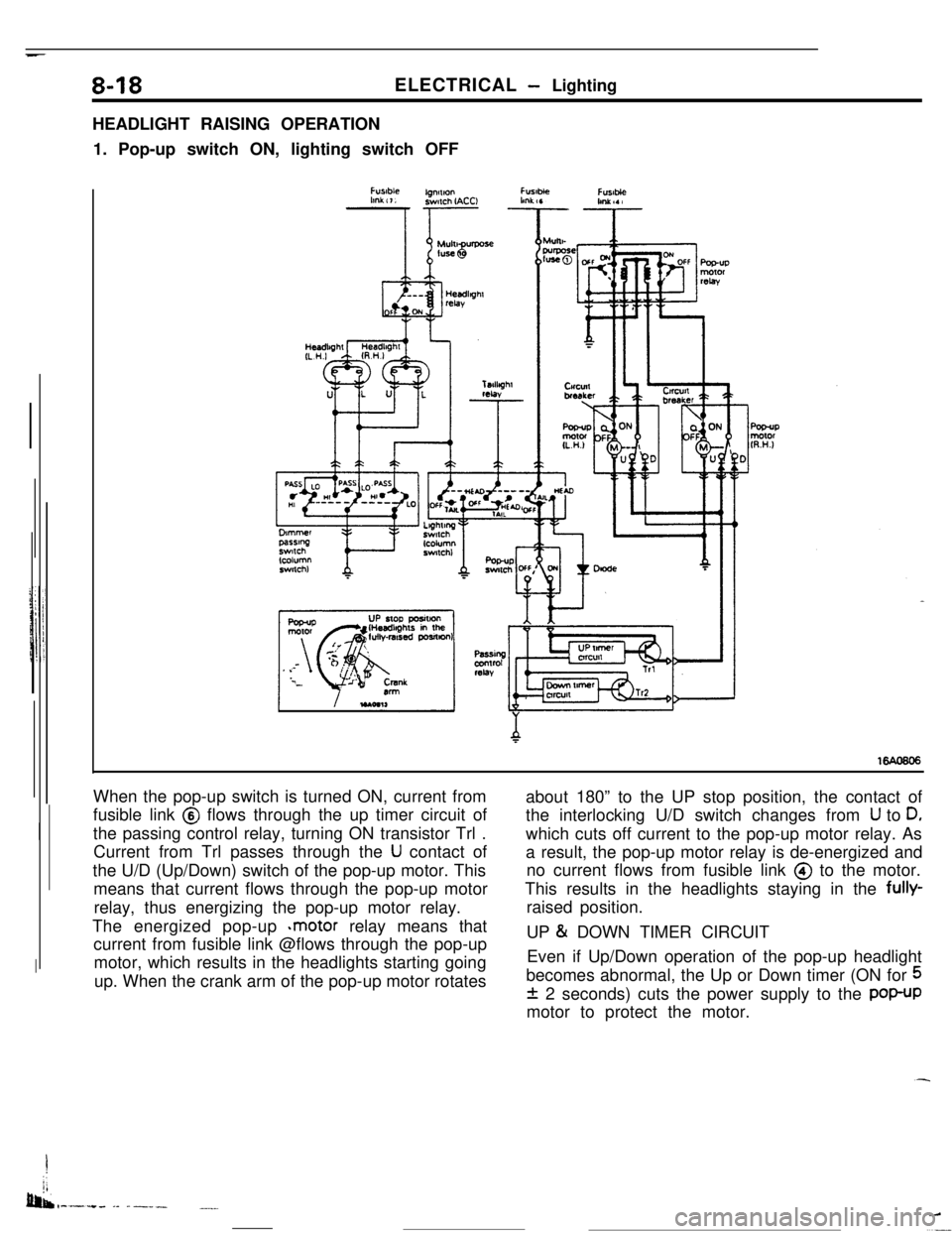
HEADLIGHT RAISING OPERATION
1. Pop-up switch ON, lighting switch OFF
When the pop-up switch is turned ON, current from
fusible link @ flows through the up timer circuit of
the passing control relay, turning ON transistor Trl .
Current from Trl passes through the
U contact of
the U/D (Up/Down) switch of the pop-up motor. This
means that current flows through the pop-up motor
relay, thus energizing the pop-up motor relay.
The energized pop-up
*motor relay means that
current from fusible link @flows through the pop-up
motor, which results in the headlights starting going
up. When the crank arm of the pop-up motor rotatesabout 180” to the UP stop position, the contact of
the interlocking U/D switch changes from
U to D,which cuts off current to the pop-up motor relay. As
a result, the pop-up motor relay is de-energized and
no current flows from fusible link @ to the motor.
This results in the headlights staying in the fully-
raised position.
UP
& DOWN TIMER CIRCUIT
Even if Up/Down operation of the pop-up headlight
becomes abnormal, the Up or Down timer (ON for
5
f 2 seconds) cuts the power supply to the POP-UPmotor to protect the motor.
I
jj
bib,-.-.+. -- ------.__
Page 72 of 391
_ -. _ -.__-ELECTRICAL
- Lighting
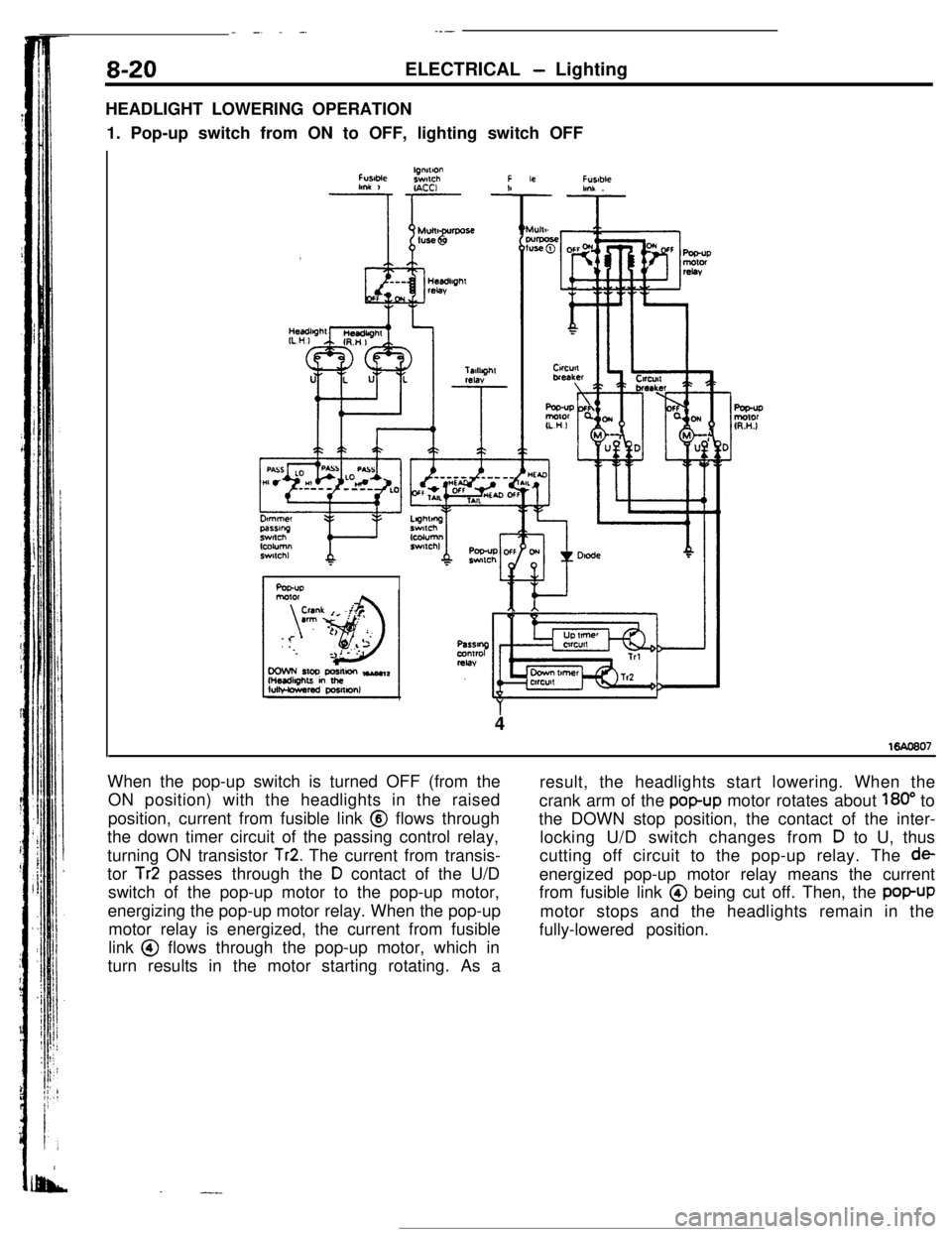
HEADLIGHT LOWERING OPERATION
1. Pop-up switch from ON to OFF, lighting switch OFF
FUslMelgnnlonswlchFlmk 1r- -!IACCI
Ar
Fusablehnk .
4
When the pop-up switch is turned OFF (from the
ON position) with the headlights in the raised
position, current from fusible link @ flows through
the down timer circuit of the passing control relay,
turning ON transistor
Tr2. The current from transis-
tor
Tr2 passes through the D contact of the U/D
switch of the pop-up motor to the pop-up motor,
energizing the pop-up motor relay. When the pop-up
motor relay is energized, the current from fusible
link @ flows through the pop-up motor, which in
turn results in the motor starting rotating. As a
.-.-result, the headlights start lowering. When the
crank arm of the
popup motor rotates about 180” to
the DOWN stop position, the contact of the inter-
locking U/D switch changes from
D to U, thus
cutting off circuit to the pop-up relay. The
deenergized pop-up motor relay means the current
from fusible link @ being cut off. Then, the
popUPmotor stops and the headlights remain in the
fully-lowered position.
Page 85 of 391
ELECTRICAL - Theft-alarm System8-33ARMING THE SYSTEM
After the following procedures have been completed, the SECURITY light illuminates for about 20 seconds,
and when illumination stops, the system is armed.
(1) Pull out the ignition key from the key cylinder.
(2) Open a door. (The other door is closed.)
(3) Lock the door with the key or the
keyless-locking method.
(The central door locking system will then function to lock all doors.)
NOTE(1) The system is set regardless of whether the hood and liftgate are open or
closed, and is armed as
soon as the light goes out.
(2) Even after the system has been armed, if the key is used to open the liftgate, the system will not be
activated; when the liftgate is then
closed, moreover, the system will be armed.
DISARMING THE SYSTEM
(1) The system will be disarmed if the key is used to unlock a door.
(2) If the system is armed while the driver is still in the vehicle, the system can be disarmed by inserting the
ignition key and turning it to the ACC or ON position.
(3) If the door lock is unlocked while closing the door or the door is ajar.
(4) If the door is unfastened while the SECURITY light illuminates.
ACTIVATING THE ALARM
(1) if an attempt is made to open a door, the liftgate or the hood, without using the key, while the system is
armed, the horn will sound intermittently and the headlights will flash on and off for approximately
three,
minutes.Furthermore, the starter circuit is interrupted at this time also, making starting of the engine impossible.
(2) if a further attempt at *forcible entry is made after the first three-minute alarm has finished, the
three-minute alarm will be activated again.
DEACTIVATING THE ALARM
(1) To deactivate the alarm, insert the key into the door’s key cylinder and turn the key.
(2) The alarm is deactivated and the system is disarmed when the iiftgate is unlocked with the key.
CHECKING THE SYSTEM OPERATION
The activation/operation of the system can be checked by following the steps below.
(1) Turn the ignition key to the ON position and then use the power-window switch to fully open the window
at the driver’s seat side.
(2) Turn the ignition key to the LOCK position and then remove the key from the ignition.
(3) Open only the driver’s door, and close all the other doors, as well as the hood and the rear hatch.
(4) Lock the driver’s door by the key or the
keyless-locking method.
(5) All doors will then be
locked, and the SECURITY light (within the combination meter) will illuminate; check
to be sure that illumination stops in about 20 seconds.
(6) After about two seconds have passed after the SECURITY light illumination stopped, reach through the
window of the driver’s door, pull up the lock lever to unlock the door, and then open the door.
(7) Check to be sure that, when the door is opened, the horn starts sounding and the headlights flash on and
Off.
(8) To stop the alarm, insert the key into the door’s key cylinder and turn the key.
!?iEeck the alarm for the opening of the liftgate or hood open the liftgate (or the hood) by using the
remote liftgate release lever (or the hood release lever),
located at the driver’s seat side either before the
alarm is activated by the opening of a door, or after the finish of the first three-minute alarm.
Page 107 of 391
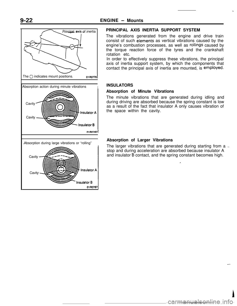
9-22ENGINE- Mounts
Principalaxi? of inertia
The
::I: indicates mount positions.01 RO77OlAbsorption action during minute vibrations
ICavity
CavityOlRcl767l
Absorption during large vibrations or “rolling”
Cavity
CavityPRINCIPAL AXIS INERTIA SUPPORT SYSTEM
The vibrations generated from the engine and drive train
consist of such eiements as vertical vibrations caused by the
engine’s combustion processes, as well as
rollings caused by
the torque reaction force of the tyres and the crankshaft
rotation etc.
In order to effectively suppress these vibrations, the principal
axis of inertia support system, by which the components that
contact the principal axis of inertia are mounted, is employed.
INSULATORS
Absorption of Minute Vibrations
The minute vibrations that are generated during idling and
during driving are absorbed because the spring constant is low
as a result of the fact that insulator A only causes vibration of
the space within the cavity.
Absorption of Larger Vibrations
The larger vibrations that are generated during starting from a
_stop and during acceleration are absorbed because insulator A
and insulator
B contact, and the spring constant becomes high.
Page 120 of 391
14-8
rFUEL SYSTEM
-Fuel Supply and Fuel Pressure Control
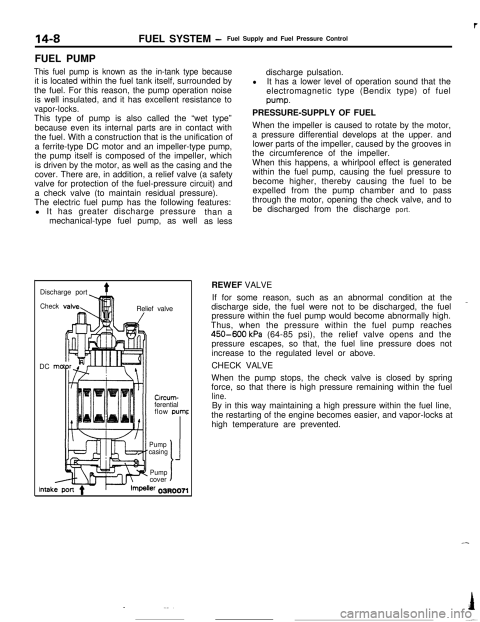
FUEL PUMP
This fuel pump is known as the in-tank type becauseit is located within the fuel tank itself, surrounded by
the fuel. For this reason, the pump operation noise
is well insulated, and it has excellent resistance to
vapor-locks.This type of pump is also called the “wet type”
because even its internal parts are in contact with
the fuel. With a construction that is the unification of
a ferrite-type DC motor and an impeller-type pump,
the pump itself is composed of the impeller, which
is driven by the motor, as well as the casing and the
cover. There are, in addition, a relief valve (a safety
valve for protection of the fuel-pressure circuit) and
a check valve (to maintain residual pressure).
The electric fuel pump has the following features:
l It has greater discharge pressure
mechanical-type fuel pump, as wellthan a
as lessdischarge pulsation.
lIt has a lower level of operation sound that the
electromagnetic type (Bendix type) of fuelpump.
PRESSURE-SUPPLY OF FUEL
When the impeller is caused to rotate by the motor,
a pressure differential develops at the upper. and
lower parts of the impeller, caused by the grooves in
the circumference of the impeller.
When this happens, a whirlpool effect is generated
within the fuel pump, causing the fuel pressure to
become higher, thereby causing the fuel to be
expelled from the pump chamber and to pass
through the motor, opening the check valve, and to
be discharged from the discharge port.
Discharge port
4Check!nRelief valve
DC mo
-lllll1 I/
Circum-ferential
flow pumr
II’ f-Pump
casing
J
Pumpcovert
lntakler 03R0071REWEF VALVE
If for some reason, such as an abnormal condition at the
_discharge side, the fuel were not to be discharged, the fuel
pressure within the fuel pump would become abnormally high.
Thus, when the pressure within the fuel pump reaches
450-600 kPa (64-85 psi), the relief valve opens and the
pressure escapes, so that, the fuel line pressure does not
increase to the regulated level or above.
CHECK VALVE
When the pump stops, the check valve is closed by spring
force, so that there is high pressure remaining within the fuel
line.By in this way maintaining a high pressure within the fuel line,
the restarting of the engine becomes easier, and vapor-locks at
high temperature are prevented.
-
-_..I
-~
Page 186 of 391
14-74
_ ,.-..FUEL SYSTEM
- Auto-cruise Control System
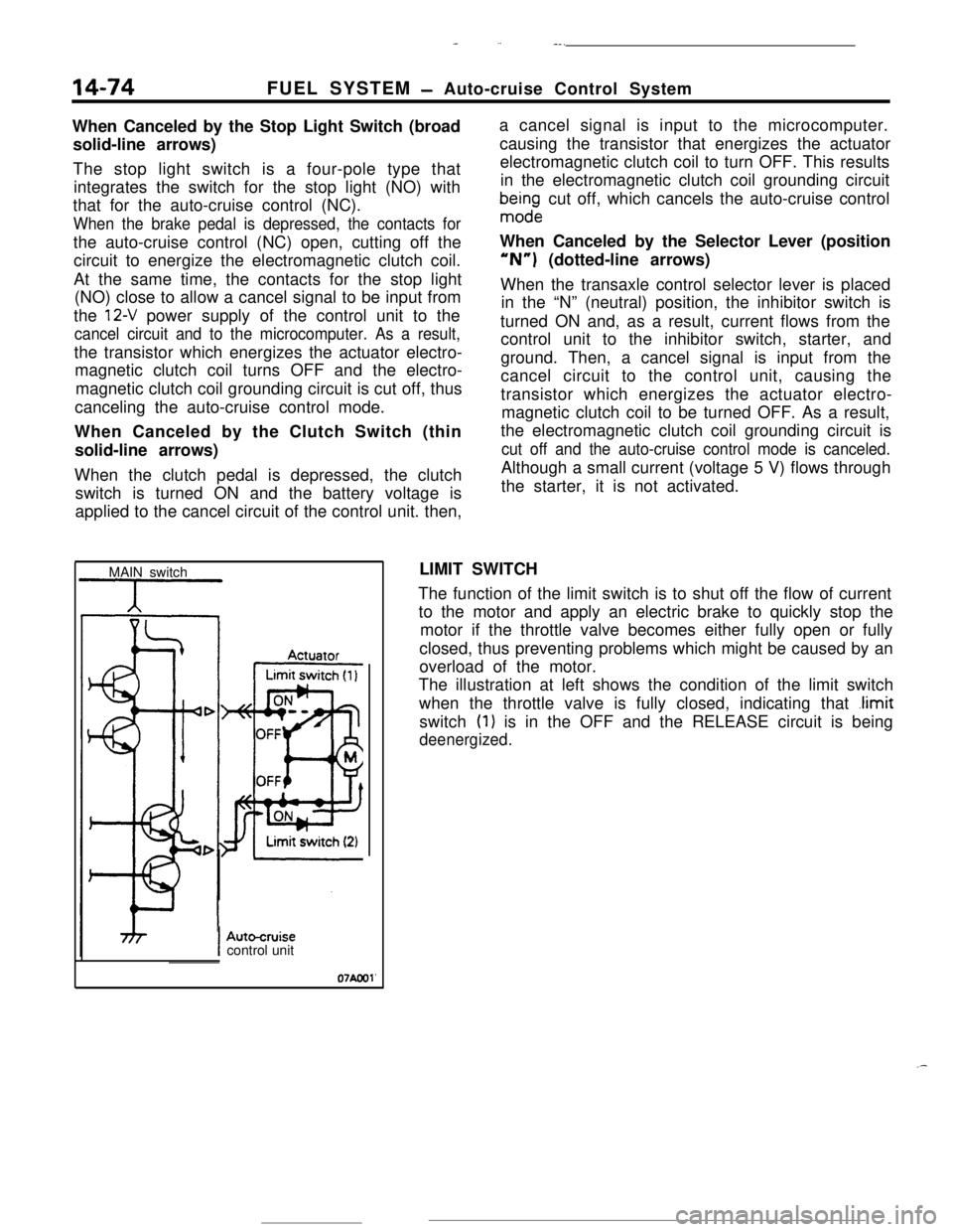
When Canceled by the Stop Light Switch (broad
solid-line arrows)
The stop light switch is a four-pole type that
integrates the switch for the stop light (NO) with
that for the auto-cruise control (NC).
When the brake pedal is depressed, the contacts forthe auto-cruise control (NC) open, cutting off the
circuit to energize the electromagnetic clutch coil.
At the same time, the contacts for the stop light
(NO) close to allow a cancel signal to be input from
the
12-V power supply of the control unit to the
cancel circuit and to the microcomputer. As a result,the transistor which energizes the actuator electro-
magnetic clutch coil turns OFF and the electro-
magnetic clutch coil grounding circuit is cut off, thus
canceling the auto-cruise control mode.
When Canceled by the Clutch Switch (thin
solid-line arrows)
When the clutch pedal is depressed, the clutch
switch is turned ON and the battery voltage is
applied to the cancel circuit of the control unit. then,a cancel signal is input to the microcomputer.
causing the transistor that energizes the actuator
electromagnetic clutch coil to turn OFF. This results
in the electromagnetic clutch coil grounding circuit
bma$ndge cut off, which cancels the auto-cruise control
When Canceled by the Selector Lever (position“N”) (dotted-line arrows)
When the transaxle control selector lever is placed
in the “N” (neutral) position, the inhibitor switch is
turned ON and, as a result, current flows from the
control unit to the inhibitor switch, starter, and
ground. Then, a cancel signal is input from the
cancel circuit to the control unit, causing the
transistor which energizes the actuator electro-
magnetic clutch coil to be turned OFF. As a result,
the electromagnetic clutch coil grounding circuit is
cut off and the auto-cruise control mode is canceled.Although a small current (voltage 5 V) flows through
the starter, it is not activated.
MAIN switchLIMIT SWITCH
The function of the limit switch is to shut off the flow of current
to the motor and apply an electric brake to quickly stop the
motor if the throttle valve becomes either fully open or fully
closed, thus preventing problems which might be caused by an
overload of the motor.
The illustration at left shows the condition of the limit switch
when the throttle valve is fully closed, indicating that
.limitswitch
(1) is in the OFF and the RELEASE circuit is being
deenergized.
IAutocruisecontrol unit
07Aool'
.-
Page 189 of 391
-- --.-*-.e *._,_-.&” :,.>~‘c,-.y~~ 7, . . --
FUEL SYSTEM- Auto-cruise Control System14-77
(For stop light)
OFF +-ON
0N -+-OFF
(For auto-cruise control)
16RO99r4 3
12
NCNO-w-w
I/0l-COFFOFF*~ON4
321NO: Normally opened
NC: Normally closed
07AOOl:
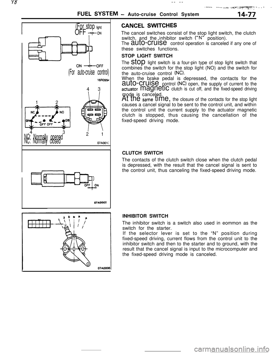
CANCEL SWITCHESThe cancel switches consist of the stop light switch, the clutch
switch, and the inhibitor switch
(“N” position).
The auto-cruise control operation is canceled if any one ofthese switches functions.
STOP LIGHT SWITCH
The stop light switch is a four-pin type of stop light switch thatcombines the switch for the stop light (NO) and the switch for
the auto-cruise control
(NC).When the brake pedal is depressed, the contacts for the
auto-cruise control (NC) open, the supply of current to the
actuator magnetic clutch is cut off, and the fixed-speed drivingmode is canceled.
At the Same time, the closure of the contacts for the stop lightcauses a cancel signal to be sent to the control unit, and within
the control unit the current supply to the actuator magnetic
clutch is stopped, thus causing the cancellation of the
fixed-speed driving mode.
CLUTCH SWITCH
The contacts of the clutch switch close when the clutch pedal
is depressed, with the result that the cancel signal is sent to
the control unit, thus canceling the fixed-speed driving mode.
INHIBITOR SWITCH
The inhibitor switch is a switch also used in eommon as the
switch for the starter.
If the selector lever is set to the “N” position during
fixed-speed driving, current flows from the control unit to the
inhibitor switch and then to the starter and to ground, with the
result that the cancel signal is input to the microcomputer and
the fixed-speed driving mode is canceled.
Page 248 of 391
21-24AUTOMATIC TRANSAXLE - Transaxle Mechanism
SELECT PATTERN
Select pattern refers to the indication of transaxle
positions to be manually selected by the driver. This
transaxie is provided with 6 positions: P-R-N-D-
2-L. The following contains the explanations of the
function of each position selected.
P-Parking
(1)
(2)
(3)
Each element does not operate at all. Therefore,the engine output is not transmitted to the
output shaft.
The output shaft is completely locked by mecha-
nical means. Therefore, the vehicle does not
move in forward or reverse direction.
The engine can be started.
R-Reverse
(1) The vehicle moves in reverse direction.
(2) The engine cannot be started.
N-Neutral
(1) The engine output is not transmitted to the
output shaft as in the case of
“P”(2) The engine can be started.
D-Drive
(1)
(2)
(3)Corresponding with the degree that the
accelerator pedal is pressed down (i.e. throttle
opening) and vehicle speed,
“D” automatically
shifts between forward 4 speeds. Note, howev-
er,’ that the forward 3 speeds are selected when
the overdrive control switch is OFF. The automa-tic shifting (up or down) is performed according
to the shift pattern shown in the illustration on
page 2
l-30.Driving-off is always performed in
1st gear.Kickdown refers to the downshift that is per-
formed if the accelerator pedal is pressed down
(4)
(5)when the vehicle is running. in
2nd. 3rd or 4t,.
gear. It is performed when the load exceeds the
downshift point.
This function
IS useful when the driver isaccelerating to pass another vehicle.
Engine brake does not function when the shift is
in
1st gear.
When the vehicle is stopped, shifting is made to
the
2nd gear to minimize creep and vibration.
Upon starting, shifting is made to
1st gear.
S-Second
(1)
(2)
(3)“2” automatically shifts between
1st and 2ndgears. This means no upshift to
3rd gear occurs.
Driving-off is always performed in
1st gear.
Downshift to
2nd or 3rd gear is performed by
selecting the“2” range while the vehicle is
running in
3,rd or 4th gear, when a speed lower
than the set value is reached.
(4)As in the case of the “D” range, engine brake
does not work when the shift is in
1st gear.
L-Lock-up
(1)
(2)
(3)While “L” (Lock-up) performs downshift from
2nd to 1st gear, it does not shift up the gear
from
1st to 2nd or 3rd. The enables what is_.called
“1st gear holding”.
Driving-off is always performed in
1st gear.
Engine brake functions in the case of this
1st
gear..By selecting the “L” range while the vehicle is
running in the
“0” or “2” range, downshift from4th to
3rd, 3rd to 2nd, or 2nd to 1st is performed
when the vehicle reaches the respective speed
prescribed for each gear.
Page 270 of 391
---21-46AUTOMATIC TRANSAXLE
- Transaxle Control
Figure A
IICITime (sec.)f
IiFigureB ,
II
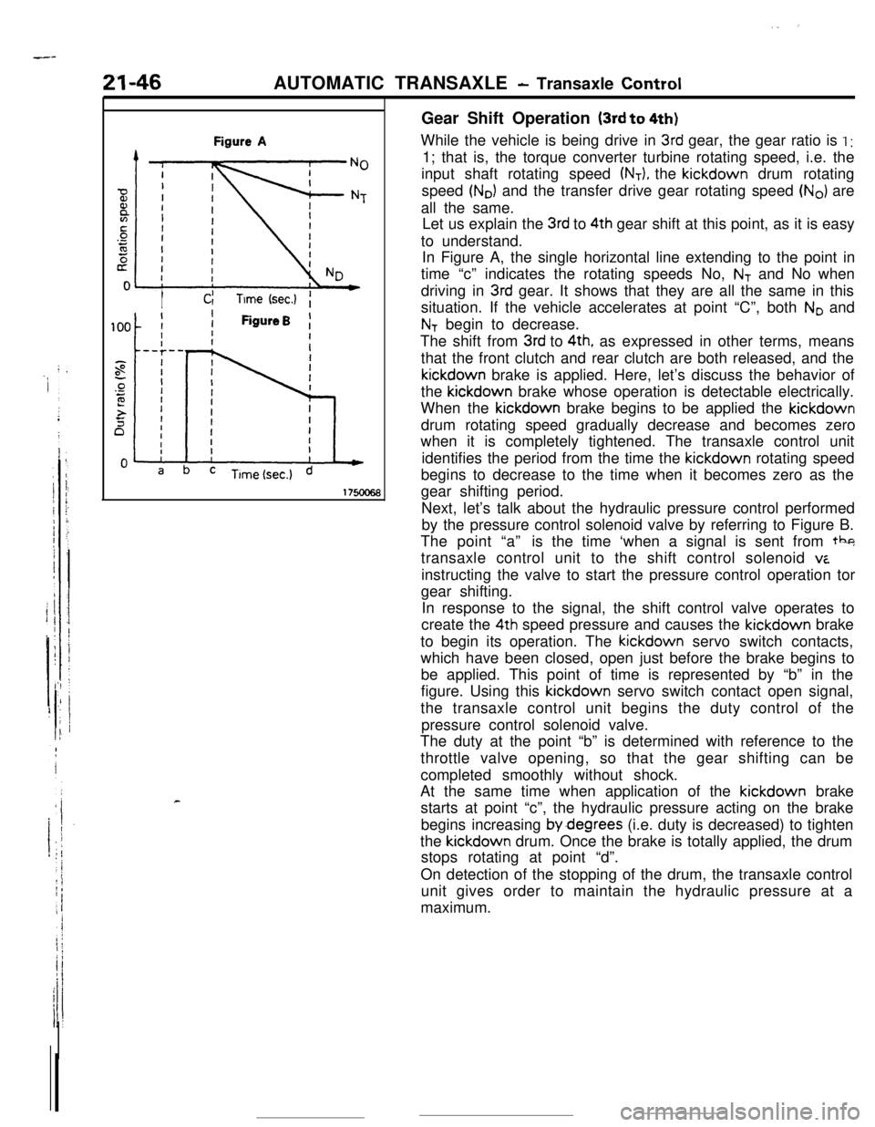
cGear Shift Operation
(3rd to 4th)While the vehicle is being drive in
3rd gear, the gear ratio is I :1; that is, the torque converter turbine rotating speed, i.e. the
input shaft rotating speed
(NT), the kickdown drum rotating
speed
(No) and the transfer drive gear rotating speed (No) are
all the same.
Let us explain the
3rd to 4th gear shift at this point, as it is easy
to understand.
In Figure A, the single horizontal line extending to the point in
time “c” indicates the rotating speeds No,
NT and No when
driving in
3rd gear. It shows that they are all the same in this
situation. If the vehicle accelerates at point “C”, both
No and
NT begin to decrease.
The shift from
3rd to 4th, as expressed in other terms, means
that the front clutch and rear clutch are both released, and thekickdown brake is applied. Here, let’s discuss the behavior of
the kickdown brake whose operation is detectable electrically.
When the kickdown brake begins to be applied the kickdown
drum rotating speed gradually decrease and becomes zero
when it is completely tightened. The transaxle control unit
identifies the period from the time the kickdown rotating speed
begins to decrease to the time when it becomes zero as the
gear shifting period.
Next, let’s talk about the hydraulic pressure control performed
by the pressure control solenoid valve by referring to Figure B.
The point “a”is the time ‘when a signal is sent from tbg
transaxle control unit to the shift control solenoid
viinstructing the valve to start the pressure control operation tor
gear shifting.
In response to the signal, the shift control valve operates to
create the 4th speed pressure and causes the kickdown brake
to begin its operation. The kickdown servo switch contacts,
which have been closed, open just before the brake begins to
be applied. This point of time is represented by “b” in the
figure. Using this kickdown servo switch contact open signal,
the transaxle control unit begins the duty control of the
pressure control solenoid valve.
The duty at the point “b” is determined with reference to the
throttle valve opening, so that the gear shifting can be
completed smoothly without shock.
At the same time when application of the kickdown brake
starts at point “c”, the hydraulic pressure acting on the brake
begins increasing by.degrees (i.e. duty is decreased) to tighten
the kickdown drum. Once the brake is totally applied, the drum
stops rotating at point “d”.
On detection of the stopping of the drum, the transaxle control
unit gives order to maintain the hydraulic pressure at a
maximum.