service MITSUBISHI ECLIPSE 1991 Service Manual
[x] Cancel search | Manufacturer: MITSUBISHI, Model Year: 1991, Model line: ECLIPSE, Model: MITSUBISHI ECLIPSE 1991Pages: 1216, PDF Size: 67.42 MB
Page 214 of 1216

5-74BRAKES -Rear Disc Brake
1410062
14R0050
14UOO72
SERVICE POINTS OF DISASSEMBLYNO5NBAEWhen disassembling the rear disc brakes, disassemble both
sides (left and right) as a set.
3. REMOVAL OF SUPPORT MOUNTINGWith the lock pin removed, pull the support mounting off
from the caliper body.
9. DISASSEMBLY OF PISTON ASSEMBLYUse the special tool to twist the piston out of the caliper
body.
10. DISASSEMBLY OF PISTON SEAL
(1) Remove piston seal with finger tip.
Caution
Do not use flat tip (-) screwdriver or other tool to
prevent damage to inner cylinder.(2) Clean piston surface and inner cylinder with
trichloro-ethylene, alcohol or specified brake fluid.
Specified brake fluid: MOPAR Brake Fluid/
Conforming to DOT3
11. DISASSEMBLY OF SNAP RINGWhile using a 19 mm
(75 in.) diameter steel pipe to press
the spring case into the caliper body, use the snap ring
pliers to remove the snap ring from the caliper body.
INSPECTIONN65NCAAa
e Check the connecting link and the spindle for wear or
damage.l
l Check the spindle lever shaft for rust.
l
l Check the piston for rust.
Check the piston seal for wear or deterioration.
l
piston
PAD WEAR CHECK(1) Measure the thickness of the pad at the thinnest place.
(.08(2) If the pad assemblies are worn beyond the limit, replace
them.
Page 215 of 1216
BRAKES - Rear Disc Brake5-75
- Lever
boot14RDD52
grooves
a
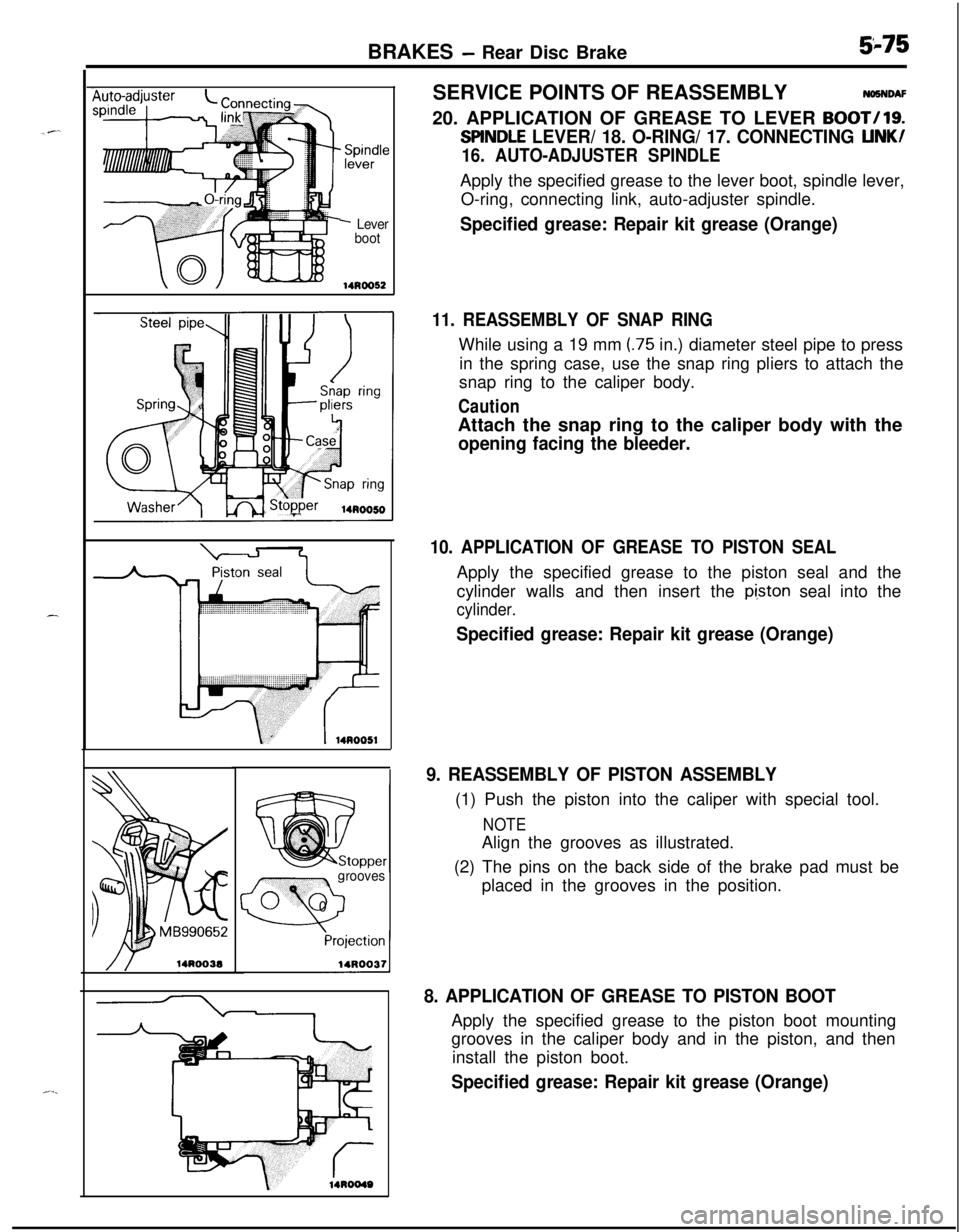
0 0SERVICE POINTS OF REASSEMBLYNiSNDAF
20. APPLICATION OF GREASE TO LEVER
BOOT/19.
SllNDLE LEVER/ 18. O-RING/ 17. CONNECTING LINK/
16. AUTO-ADJUSTER SPINDLEApply the specified grease to the lever boot, spindle lever,
O-ring, connecting link, auto-adjuster spindle.
Specified grease: Repair kit grease (Orange)
11. REASSEMBLY OF SNAP RINGWhile using a 19 mm
(.75 in.) diameter steel pipe to press
in the spring case, use the snap ring pliers to attach the
snap ring to the caliper body.
CautionAttach the snap ring to the caliper body with the
opening facing the bleeder.
10. APPLICATION OF GREASE TO PISTON SEALApply the specified grease to the piston seal and the
cylinder walls and then insert the
pi,ston seal into the
cylinder.
Specified grease: Repair kit grease (Orange)
9. REASSEMBLY OF PISTON ASSEMBLY(1) Push the piston into the caliper with special tool.
NOTEAlign the grooves as illustrated.
(2) The pins on the back side of the brake pad must be
placed in the grooves in the position.
8. APPLICATION OF GREASE TO PISTON BOOTApply the specified grease to the piston boot mounting
grooves in the caliper body and in the piston, and then
install the piston boot.
Specified grease: Repair kit grease (Orange)
Page 217 of 1216
BRAKES - Hydraulic Unit
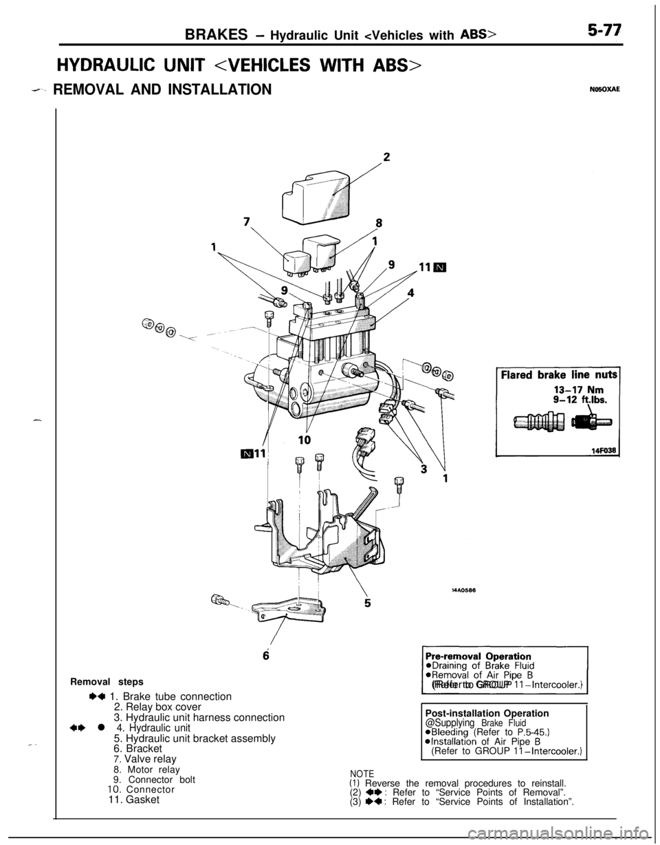
HYDRAULIC UNIT
--. REMOVAL AND INSTALLATION
6Removal steps
I)+ 1. Brake tube connection
2. Relay box cover
3. Hydraulic unit harness connection
~~ l 4. Hydraulic unit5. Hydraulic unit bracket assembly
6. Bracket
7. Valve relay
1(Refer to GROUP
II-Intercooler.)Post-installation Operation
@Supplying Brake FluidaBleeding (Refer to P.5-45.)@Installation of Air Pipe B(Refer to GROUP II-Intercooler.)8. Motor relay
9. Connector bolt
10. Connector
11. Gasket
NOTE(1) Reverse the removal procedures to reinstall.
(2) +e : Refer to “Service Points of Removal”.
(3) e+ : Refer to “Service Points of Installation”.
Page 218 of 1216
5-78BRAKES - Hydraulic Unit
SERVICE POINTS OF REMOVAL
4. REMOVAL OF HYDRAULIC UNITb-3Remove the installation nuts, and then take out the __
hydraulic unit upward.
Caution
1. The hydraulic unit is heavy, and so care should be
taken when removing it.2. The hydraulic unit is not to be disassembled; its
nuts and bolts should absolutely not be loosened.
3. The hydraulic unit must not be dropped or other-
wise subjected to impact shocks.
4.The hydraulic unit must not be turned upside downor laid on its side.
Aotor relay
16R0670
16Rl773
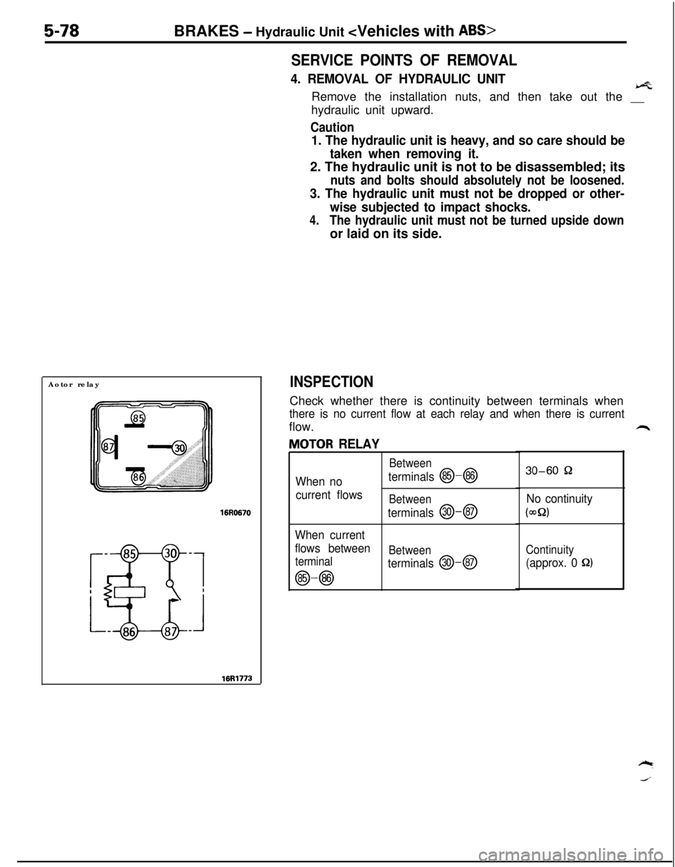
INSPECTIONCheck whether there is continuity between terminals when
there is no current flow at each relay and when there is currentflow.
JlOTOR RELAY
Between
When noterminals @-@I
current flowsBetween
terminals @I-@
When current
flows between
Between
terminal
terminals @--@
@-@
30-60 52
No continuity
(WQ)
Continuity
(approx. 0 8)
Page 219 of 1216
BRAKES -Hydraulic Unit
Jalve relay
16R0670
87a
16Rl772
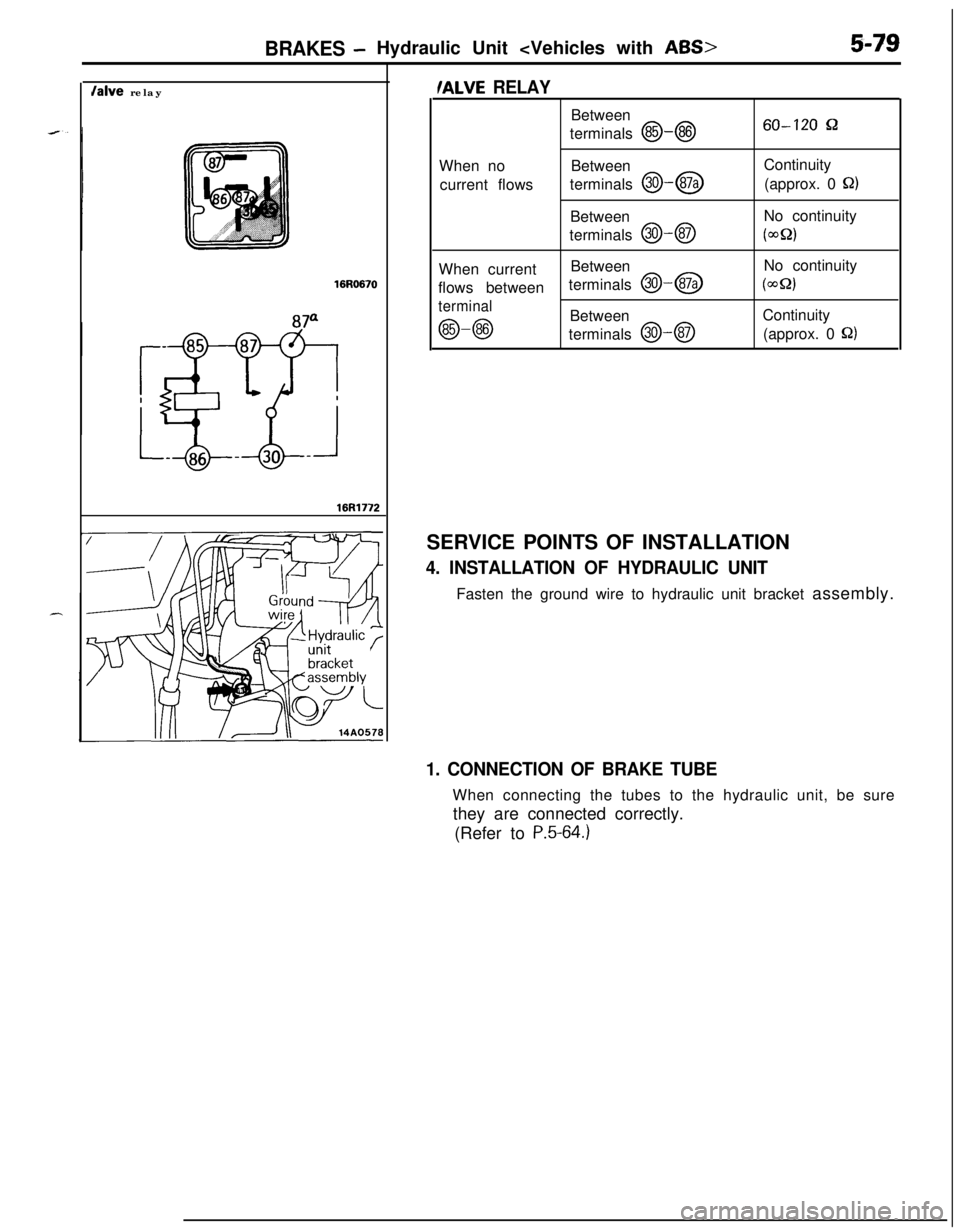
/ALVE RELAYBetween
terminals
@-@60-120 &2When noBetween
current flowsterminals
@I--@Continuity
(approx. 0 Q)Between
terminals
@J-QNo continuity(wQ2)When currentBetweenNo continuity
flows betweenterminals
@-@I(WQ)
terminal
@-@Between
terminals @--@Continuity
(approx. 0 S22)SERVICE POINTS OF INSTALLATION
4. INSTALLATION OF HYDRAULIC UNITFasten the ground wire to hydraulic unit bracket assembly.
1. CONNECTION OF BRAKE TUBEWhen connecting the tubes to the hydraulic unit, be sure
they are connected correctly.
(Refer to
P.5-64.)
Page 220 of 1216
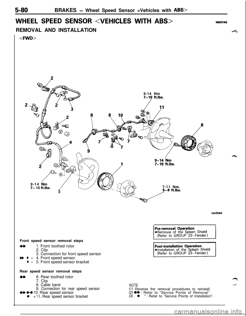
5-80BRAKES - Wheel Speed Sensor
WHEEL SPEED SENSOR
4.
7-10 ft.lbs.
-/?’9-14 Nm
7- 10 ft.lbs./5Front speed sensor removal steps
4*I. Front toothed rotor
2. Clip
3. Connection for front speed sensor
+e l +4. Front speed sensorl +5. Front speed sensor bracket7-11 Nm
14A0584Rear speed sensor removal steps
**6. Rear toothed rotor
7. Clip
8. Cable band
9. Connection for rear speed sensor
+e I)* 10. Rear speed sensorl + 11. Rear speed sensor bracket
NOTE(1) Reverse the removal procedures to reinstall.(2) 4* : Refer to “Service Points of Removal”.(3) l * : Refer to “Service Points of Installation”.
Page 221 of 1216
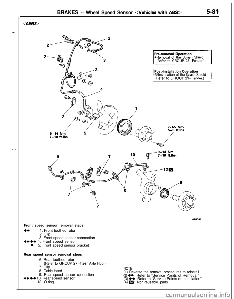
BRAKES - Wheel Speed Sensor
7-10 ft.lbs.
IPost-installation Operation@Installation of the Snlash ShieldI
1 (Refer to GROUP 23-Fender.)17-11 Nm
14A0582Front speed sensor removal steps
4*1. Front toothed rotor
2. Clip
3. Front speed sensor connection
4I) WI 4. Front speed sensor
l 5. Front speed sensor bracket
Rear speed sensor removal steps
6. Rear toothed rotor
(Refer to GROUP 27-Rear Axle Hub.)7. Clip
8. Cable band
9. Rear speed sensor connection
4I) W 10. Rear speed sensor12. O-ring
NOTE(1) Reverse the removal procedures to reinstall.(2) +e : Refer to “Service Points of Removal”.
(3) I)+ : Refer to “Service Points of Installation”.(4) m : Non-reusable parts
Page 222 of 1216
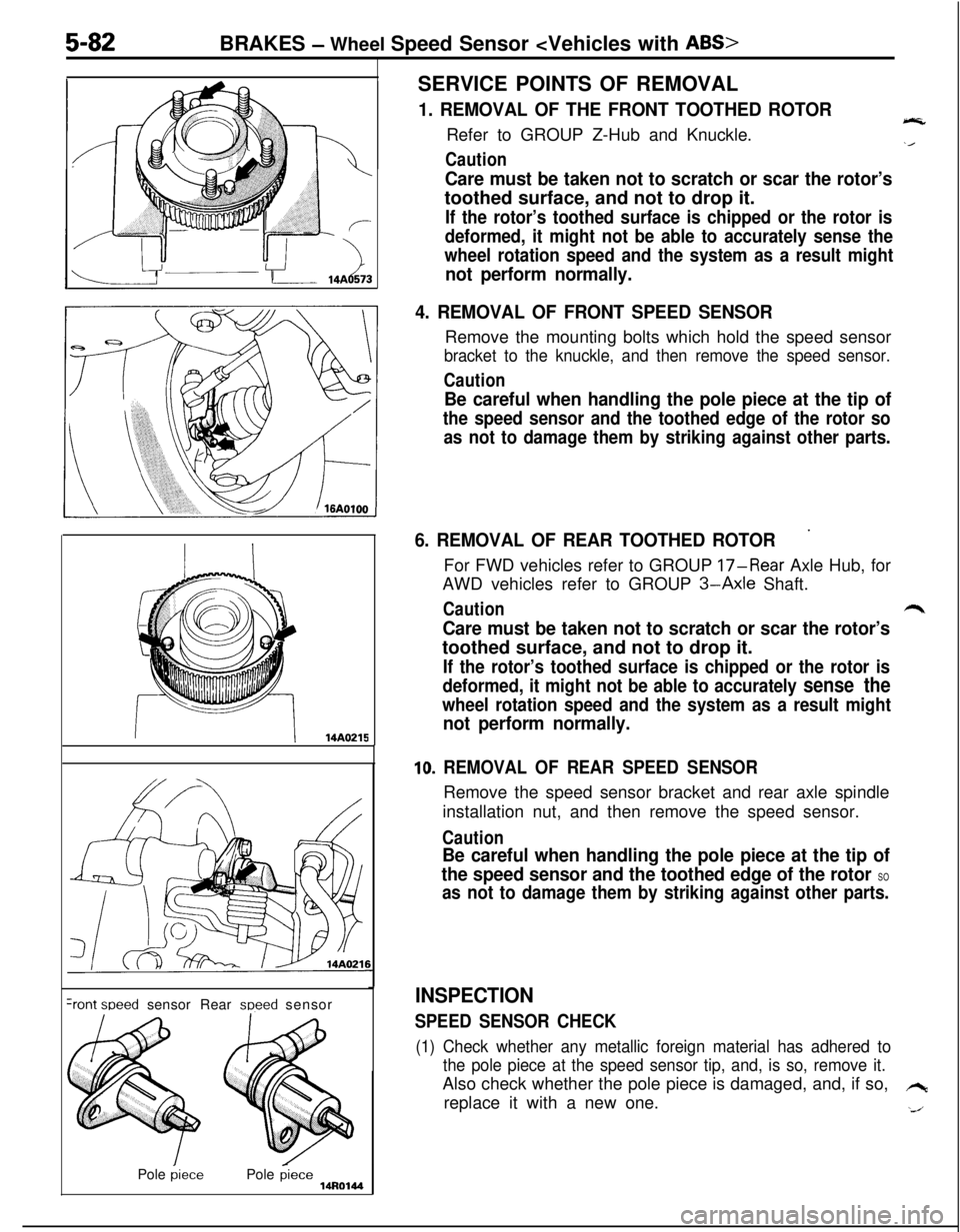
Care must be taken not to scratch or scar the rotor’stoothed surface, and not to drop it.
If the rotor’s toothed surface is chipped or the rotor is
deformed, it might not be able to accurately sense the
wheel rotation speed and the system as a result might
__ r-14A¬ perform normally.
4. REMOVAL OF FRONT SPEED SENSORRemove the mounting bolts which hold the speed sensor
bracket to the knuckle, and then remove the speed sensor.
Caution
5-82BRAKES - Wheel Speed Sensor
1. REMOVAL OF THE FRONT TOOTHED ROTOReRefer to GROUP Z-Hub and Knuckle.
Caution
Be careful when handling the pole piece at the tip of
the speed sensor and the toothed edge of the rotor so
as not to damage them by striking against other parts.
II14A0215
+ont weed sensor Rear meed sensor
Pole
piecePole piece14R0144
6. REMOVAL OF REAR TOOTHED ROTOR’For FWD vehicles refer to GROUP
17-Rear Axle Hub, for
AWD vehicles refer to GROUP
3-Axle Shaft.
Cautionr*
Care must be taken not to scratch or scar the rotor’stoothed surface, and not to drop it.
If the rotor’s toothed surface is chipped or the rotor is
deformed, it might not be able to accurately
sense the
wheel rotation speed and the system as a result might
not perform normally.
10. REMOVAL OF REAR SPEED SENSORRemove the speed sensor bracket and rear axle spindle
installation nut, and then remove the speed sensor.
Caution
Be careful when handling the pole piece at the tip of
the speed sensor and the toothed edge of the rotor
SO
as not to damage them by striking against other parts.
INSPECTION
SPEED SENSOR CHECK
(1) Check whether any metallic foreign material has adhered to
the pole piece at the speed sensor tip, and, is so, remove it.Also check whether the pole piece is damaged, and, if so,
hreplace it with a new one.
‘J
Page 223 of 1216
BRAKES - Wheel Speed Sensor
Front
Rear
14AO04814R0146
0R
Qfs0
0 (-Jor
L/
14AOO47
NOTEThe pole piece can become magnetized because of the
magnet built into the speed sensor, with the result that
metallic foreign material easily adheres to it. Moreover, the
pole piece may not be able to function to correctly sense
the wheel rotation speed if it is damaged.
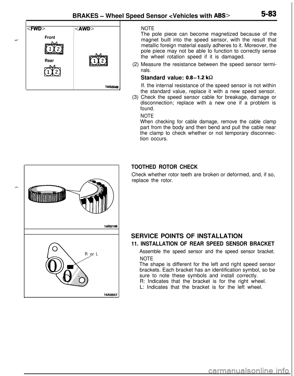
(2) Measure the resistance between the speed sensor termi-
nals.Standard value:
0.8-1.2 kQIf. the internal resistance of the speed sensor is not within
the standard value, replace it with a new speed sensor.
(3) Check the speed sensor cable for breakage, damage or
disconnection; replace with a new one if a problem is
found.
NOTE
When checking for cable damage, remove the cable clamppart from the body and then bend and pull the cable near
the clamp to check whether or not temporary disconnec-
tion occurs.
TOOTHED ROTOR CHECKCheck whether rotor teeth are broken or deformed, and, if so,
replace the rotor.
SERVICE POINTS OF INSTALLATION
11. INSTALLATION OF REAR SPEED SENSOR BRACKET
Assemble the speed sensor and the speed sensor bracket.
NOTEThe shape is different for the left and right speed sensor
brackets. Each bracket has an identification symbol, so be
sure to note these symbols and install correctly.
R: Indicates that the bracket is for the right wheel.
L: Indicates that the bracket is for the left wheel.
Page 227 of 1216
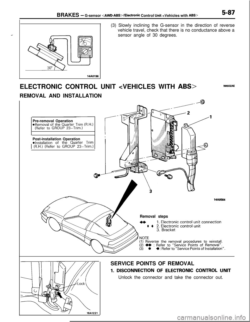
BRAKES - G-sensor
I
14AO198(3) Slowly inclining the G-sensor in the direction of reverse
vehicle travel, check that there is no conductance above a
sensor angle of 30 degrees.
ELECTRONIC CONTROL UNIT
Pre-removal Operation
@Removal of the Quarter Trim (R.H.)(Refer to GROUP 23-Trim.)IPost-installation Operation
4*Installation of the
Quarter TrimI1 (RIt?.) (Refer to GROUP 23-Trim.)1
14AO584
Removal steps
4*1. Electronic control unit connection
l +2. Electronic control unit3. Bracket
NOTE(I) Reverse the removal procedures to reinstall.(2) 4e : Refer to “Service Points of Removal”.(3) l + : Refer to “Service Points of Installation”.
SERVICE POINTS OF REMOVAL
1. DISCONNECTION OF ELECTRONIC CONTROL UNIT
Unlock the connector and take the connector out.