169 MITSUBISHI ECLIPSE 1991 Service Manual
[x] Cancel search | Manufacturer: MITSUBISHI, Model Year: 1991, Model line: ECLIPSE, Model: MITSUBISHI ECLIPSE 1991Pages: 1216, PDF Size: 67.42 MB
Page 29 of 1216
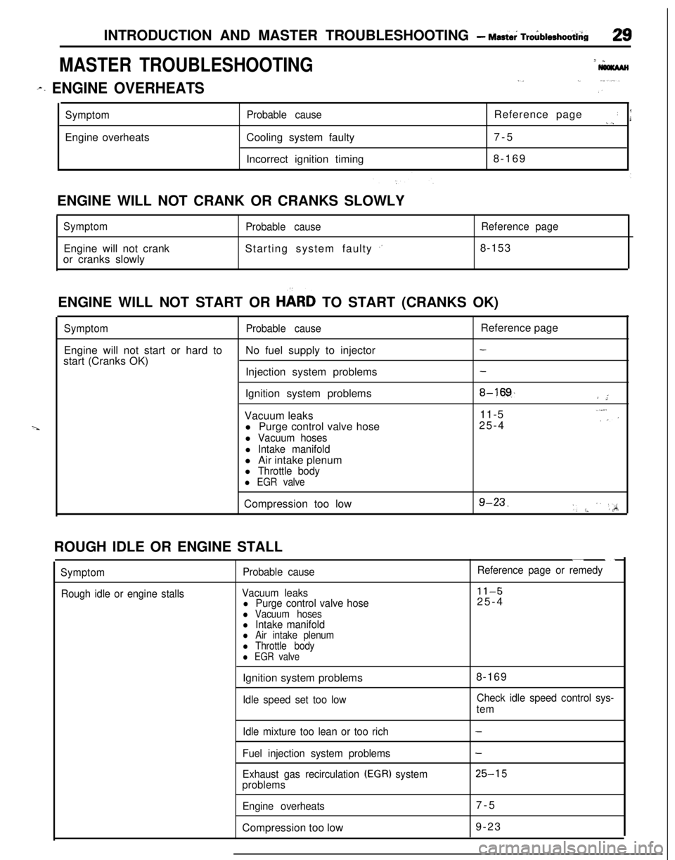
INTRODUCTION AND MASTER TROUBLESHOOTING - Mast& Tro6blerhootbia
MASTER TROUBLESHOOTING7 *
I,._ ,...
r. ENGINE OVERHEATSi ”
SymptomEngine overheatsProbable causeCooling system faulty
Incorrect ignition timingReference page: I._),7-5
8-169
ENGINE WILL NOT CRANK OR CRANKS SLOWLY
SymptomEngine will not crank
or cranks slowlyProbable causeStarting system faulty
,’
Reference page8-153
ENGINE WILL NOT START OR
HbRD TO START (CRANKS OK)
SymptomProbable causeReference page
Engine will not start or hard toNo fuel supply to injector
-start (Cranks OK)
Injection system problems
-Ignition system problems
8-16!$/ ”;Vacuum leaks11-5..“,:’l Purge control valve hose25-4
l Vacuum hoses
l Intake manifoldl Air intake plenum
l Throttle body
l EGR valveCompression too low
g-23,‘, :. ” ‘,;A;ROUGH IDLE OR ENGINE STALL
Symptom
Rough idle or engine stallsProbable cause
Vacuum leaks
l Purge control valve hosel Vacuum hosesl Intake manifoldl Air intake plenuml Throttle bodyl EGR valve
“. ._
Reference page or remedy
11-525-4
Ignition system problems
Idle speed set too low8-169Check idle speed control sys-
tem
Idle mixture too lean or too rich
Fuel injection system problems
Exhaust gas recirculation
(EGR) system
problems
Engine overheatsCompression too low
-
-
25-l 57-5
9-23
Page 30 of 1216
30INTRODUCTION AND MASTER TROUBLESHOOTING - Master Troubleshooting
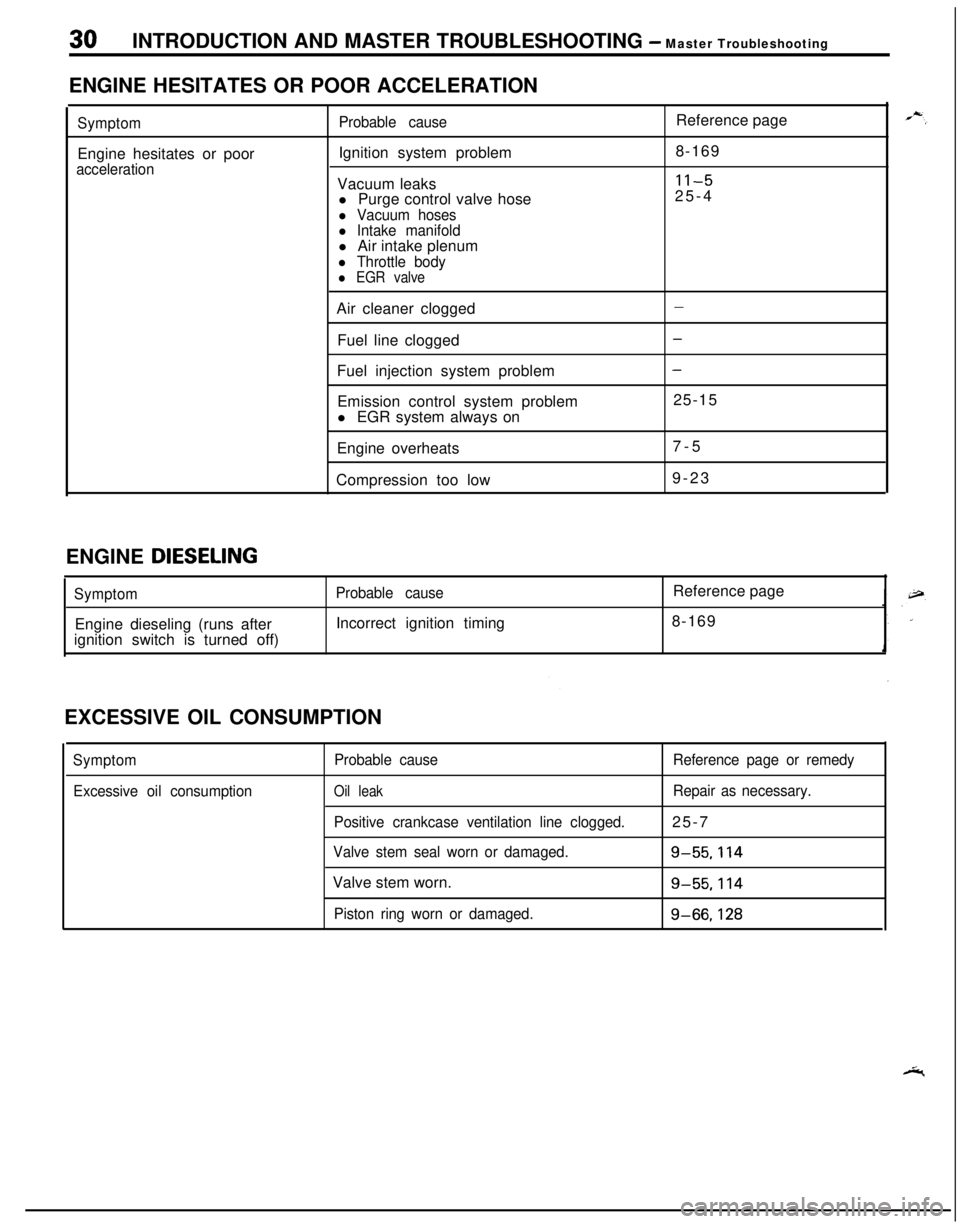
ENGINE HESITATES OR POOR ACCELERATION
SymptomEngine hesitates or poor
accelerationProbable causeIgnition system problem
Vacuum leaks
l Purge control valve hose
l Vacuum hosesl Intake manifoldl Air intake plenum
l Throttle bodyl EGR valveReference page
8-169
11-525-4
Air cleaner clogged
Fuel line clogged
Fuel injection system problem
Emission control system problem
l EGR system always on
Engine overheats
Compression too low
-
-
-25-15
7-5
9-23
ENGINE
DIESELING
SymptomEngine dieseling (runs after
ignition switch is turned off)Probable causeIncorrect ignition timingReference page
8-169
EXCESSIVE OIL CONSUMPTION
Symptom
Excessive oil consumptionProbable cause
Oil leak
Positive crankcase ventilation line clogged.
Valve stem seal worn or damaged.Valve stem worn.
Piston ring worn or damaged.Reference page or remedy
Repair as necessary.25-7
g-55.114
g-55.114
g-66,128
Page 31 of 1216
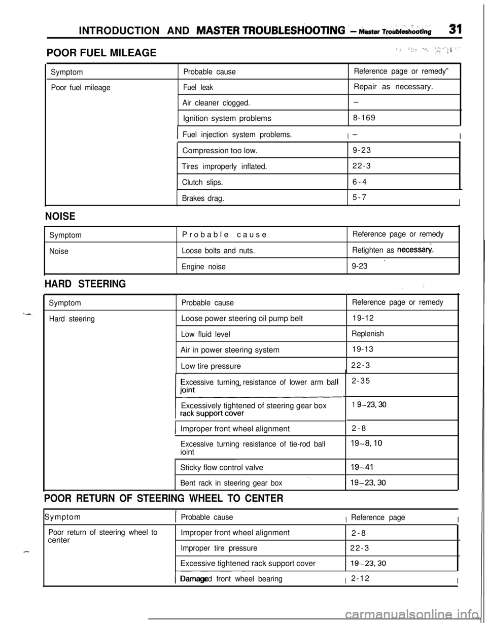
INTRODUCTION AND MASTER TROUBLESH’OOTING .- Master ~pAi&oOti~31POOR FUEL MILEAGE
../, *,, /S./..‘, _I, #_.a,‘.rr?
Symptom
Poor fuel mileageProbable cause
Fuel leak
Air cleaner clogged.Ignition system problems
Reference page or remedy”Repair as necessary.
-8-169
IFuel injection system problems.I-ICompression too low.9-23
Tires improperly inflated.22-3
Clutch slips.6-4
Brakes drag.5-7I
NOISE
Symptom
NoiseProbable cause
Loose bolts and nuts.
Engine noiseReference page or remedy
Retighten as necessary
9-23
’
HARD STEERING
Symptom
Hard steeringProbable causeLoose power steering oil pump belt
Low fluid levelAir in power steering system
Low tire pressure
Reference page or remedy19-12
Replenish19-13
22-3
Excessive turning resistance of lower arm ballExcessively tightened of steering gear box
IImproper front wheel alignment2-8
Excessive turning resistance of tie-rod ballioint2-35
1 i-23.30
19-8.10Sticky flow control valve
Bent rack in steering gear box‘.19-4119-23.30
POOR RETURN OF STEERING WHEEL TO CENTERSymptom
1Probable causeIReference pageI
Poor return of steering wheel tocenterImproper front wheel alignment
2-8
Improper tire pressure22-3
Excessive tightened rack support cover19-23.30
I-- ~~~Damaged front wheel bearingI2-12I
Page 66 of 1216
Z-18FRONT SUSPENSION - Drive Shaft
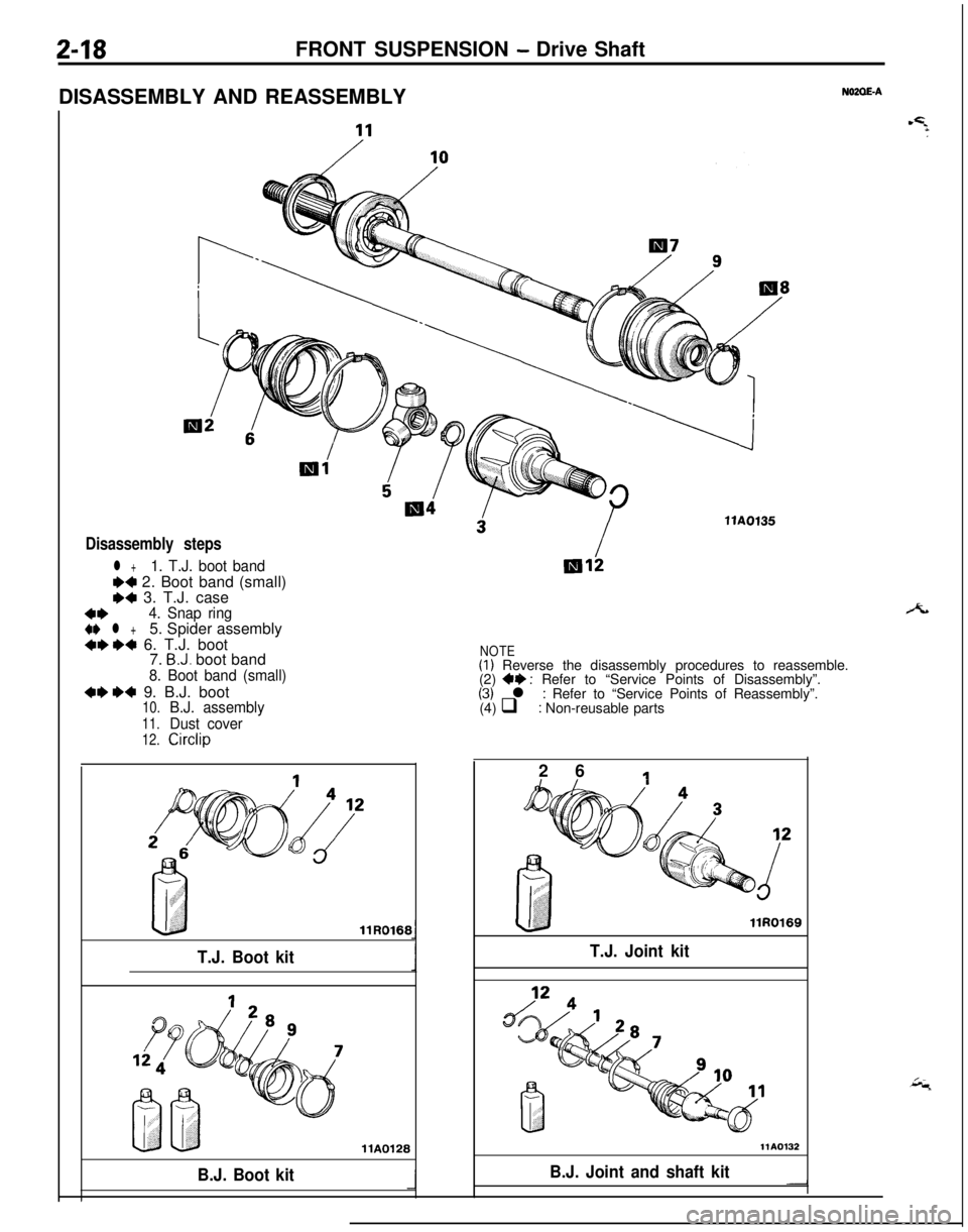
DISASSEMBLY AND REASSEMBLY
NOZOE-A
Disassembly steps
l +1. T.J. boot band
W 2. Boot band (small)e4 3. T.J. case
4*4. Snap ring
4I) l +5. Spider assembly4ee4 6. T.J. boot
7. B.J. boot band
8. Boot band (small)
4ee4 9. B.J. boot10.B.J. assembly
11.Dust cover
12.Circlip
T.J. Boot kitllR0166
llA0128
B.J. Boot kitllAOf35
NOTE(I) Reverse the disassembly procedures to reassemble.
(2) 4+ : Refer to “Service Points of Disassembly”.(3) l : Refer to “Service Points of Reassembly”.
(4) q : Non-reusable parts
2 6
1
llR0169
T.J. Joint kit
-IB.J. Joint and shaft kit
Page 98 of 1216
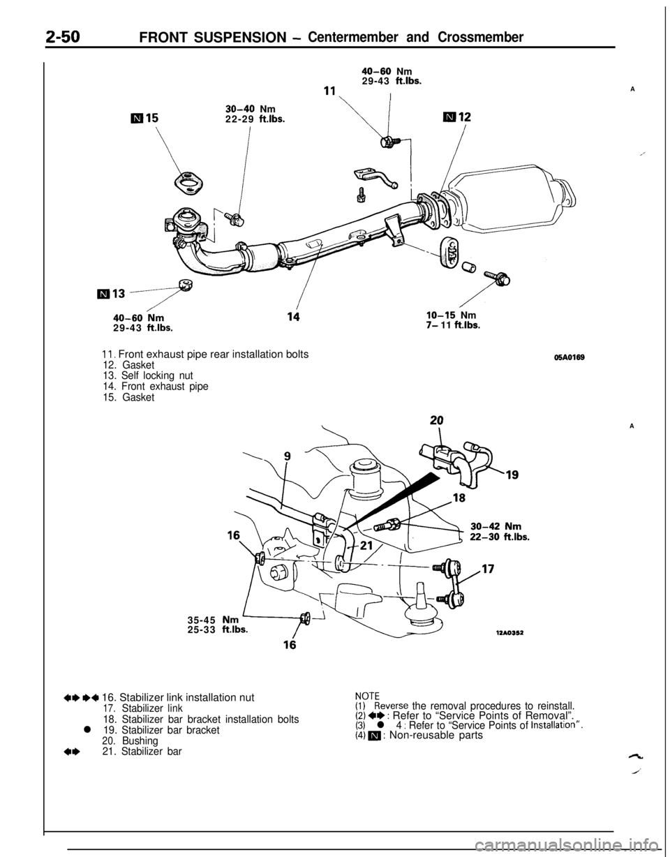
2-50FRONT SUSPENSION -Centermember and Crossmember
40-60 Nm
29-43 ftlbs.
“1I
30-40 Nm
22-29 ftlbs.
40-60 /Nm29-43 ftlbs.
11. Front exhaust pipe rear installation bolts12. Gasket
13. Self locking nut
14. Front exhaust pipe
15. Gasket35-45
25-33
IO-15 Nm7- 11 ftlbs.
22-30 ftlbs.
12AO352
+e MI 16. Stabilizer link installation nut17.Stabilizerlink
18. Stabilizer bar bracket installation boltsl 19. Stabilizer bar bracket20.Bushing
4*21. Stabilizer bar
05AO169
$?everse the removal procedures to reinstall.(2) +* : Refer to “Service Points of Removal”.(3) l 4 : Refer to “Service Points of Installatron”.(4) m : Non-reusable partsA
A’A
ct
J’
Page 186 of 1216
5-46BRAKES - Service Adjustment ProceduresWhen new
When worn
14G0017
14LO169
14A0403
\14AO400
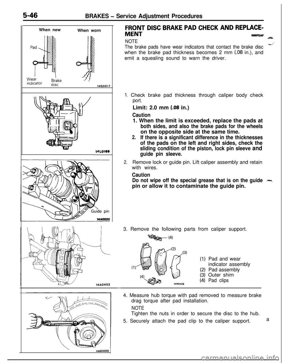
FRONT DISC BRAKE PAD CHECK AND REPLACE-
MENiNWFOAF
NOTE
The brake pads have wear indicators that contact the brake discd’when the brake pad thickness becomes 2 mm
(.08 in.), and
emit a squealing sound to warn the driver.
1. Check brake pad thickness through caliper body check
port.Limit: 2.0 mm
(.08 in.)
Caution1. When the limit is exceeded, replace the pads at
both sides, and also the brake pads for the wheelson the opposite side at the same time.
2.If there is a significant difference in the thicknesses
of the pads on the left and right sides, check the
sliding condition of the piston, lock pin sleeve and
guide pin sleeve.
2.Remove lock or guide pin. Lift caliper assembly and retain
with wires.
Caution
Do not wipe off the special grease that is on the guide
-pin or allow it to contaminate the guide pin.
3. Remove the following parts from caliper support.
=Qg@-(4)
(1)
(2)
(3)
(4)Pad and wear
indicator assembly
Pad assembly
Outer shimPad clips
-4. Measure hub torque with pad removed to measure brake
drag torque after pad installation.
NOTETighten the nuts in order to secure the disc to the hub.
5. Securely attach the pad clip to the caliper support.a
Page 768 of 1216
21-74MANUAL TRANSAXLE
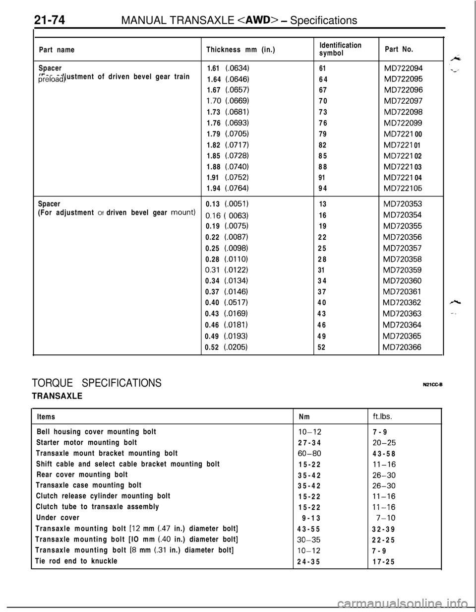
Part nameThickness mm (in.)Identification
symbolPart No.
Spacer
1.61
(.0634)61MD722094(For adjustment of driven bevel gear trainpreload)
1.64
(.0646)64MD7220951.67
(0657)67MD722096
1.70(.0669)70MD7220971.73
(0681)73MD7220981.76
(.0693)76M D7220991.79
(0705)79MD7221 00
1.82
(0717)82MD7221 011.85
(.0328)85MD7221 02
1.88
(.0740)88MD7221 03
1.91
(.0752)91MD7221 04
1.94
(0764)94MD722105Spacer
0.13
(0051)13MD720353(For adjustment Of driven bevel gear
mOWIt)o,16 ( 0063)16M D7203540.19
(0075)19MD7203550.22
(.0087)22MD7203560.25
(.0098)25MD7203570.28(.Ol
IO)28MD7203580.31
(0122)31MD7203590.34
(0134)34MD7203600.37
(0146)37MD7203610.40
(0517)40M D7203620.43
(.0169)43MD7203630.46
(0181)46MD7203640.49
(.0193)49MD7203650.52
(0205)52MD720366
TORQUE SPECIFICATIONSNZlCC-B
TRANSAXLEItems
Bell housing cover mounting bolt
Starter motor mounting bolt
Transaxle mount bracket mounting bolt
Shift cable and select cable bracket mounting bolt
Rear cover mounting bolt
Transaxle case mounting bolt
Clutch release cylinder mounting bolt
Clutch tube to transaxle assembly
Under cover
Transaxle mounting bolt
[I2 mm (47 in.) diameter bolt]
Transaxle mounting bolt [IO mm
(40 in.) diameter bolt]
Transaxle mounting bolt [8 mm (.31 in.) diameter bolt]
Tie rod end to knuckleNm
ft.lbs.
IO-127-9
27-34
20-25
60-8043-58
15-22
11-1635-42
26-3035-42
26-3015-22
11-1615-22
11-169-13
7-1043-55
32-39
30-3522-25
IO-127-9
24-3517-25
Page 855 of 1216
AUTOMATIC TRANSAXLE - SDecifications
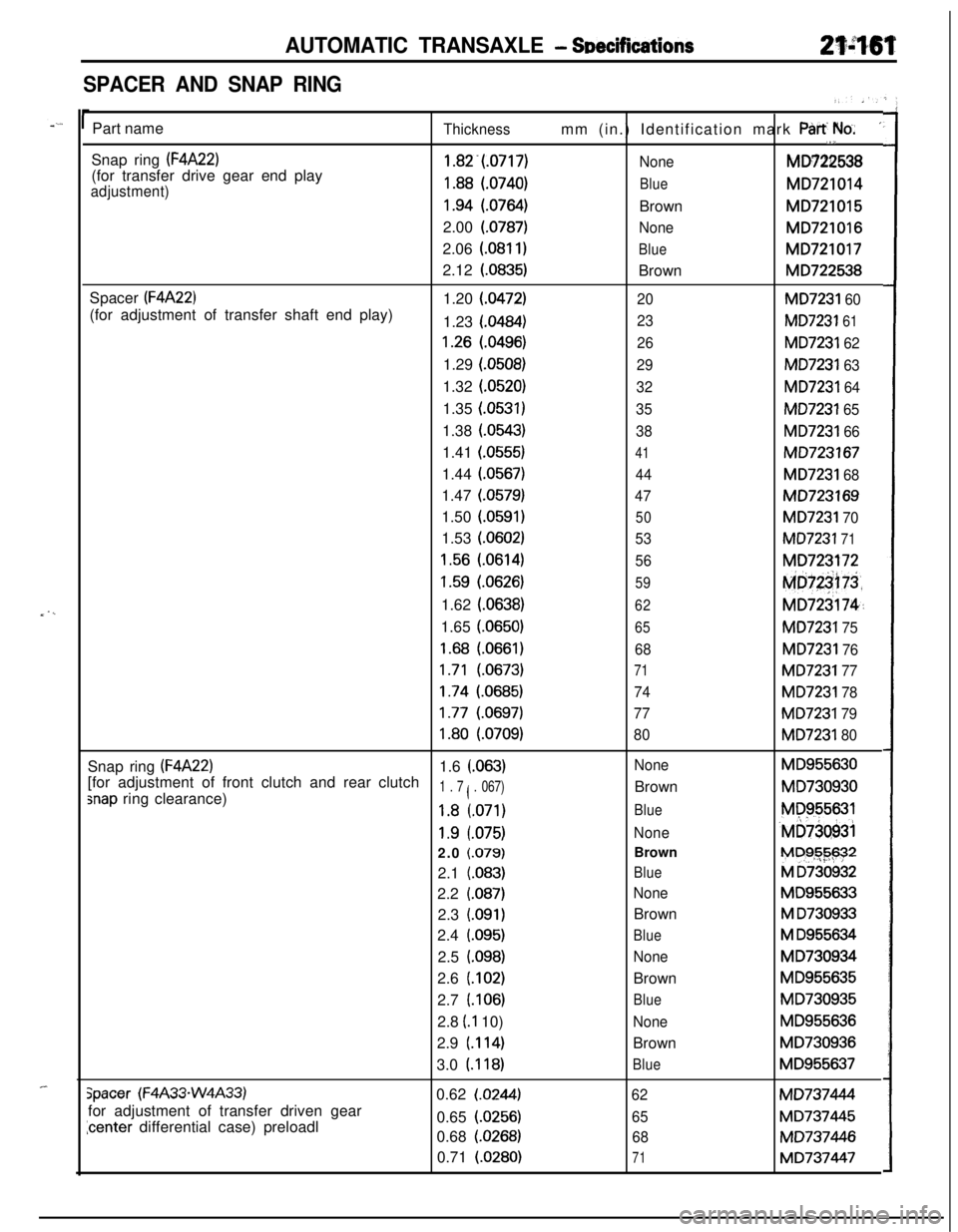
SPACER AND SNAP RING
_ . ,_
_-Part name
Thicknessmm (in.) Identification mark Part We.’,1,Snap ring
(F4A22)1.82.(.0717)
NoneMD722538
(for transfer drive gear end play
adjustment)1.88 (.0740)BlueMD721014
1.94 (.0764)BrownMD721015
2.00 (0787)
NoneMD721016
2.06
(.081 I)BlueMD7210172.12
(.0835)BrownMD722538
Spacer
(F4A22)1.20 (0472)20MD7231 60(for adjustment of transfer shaft end play)
1.23 (0484)
23MD7231 61
1.26 (.0496)26MD7231 621.29 (0508)
29MD7231 631.32 (0520)
32MD7231 641.35 (0531)
35MD7231 651.38 (0543)
38MD7231 661.41 (0555)
41MD7231671.44
(.0567)44MD7231 681.47
(.0579)47MD723169
1.50
(.0591)
50MD7231 701.53 (0602)
53MD7231 71
1.56 (.0614)56MD723172
1.59 (0626)59Md@75,1.62
(.0638)
62MD723174~:1.65 (0650)
65MD7231 75
1.68 (.0661)68MD7231 76
1.71 (.0673)71MD7231 77
1.74 (.0685)74MD7231 78
1.77 (.0697)77MD7231 79
1.80 (.0709)80MD7231 80Snap ring
(F4A22)1.6 (.063)NoneMD955630[for adjustment of front clutch and rear clutch
snap ring clearance)1 . 7 ( . 067)BrownMD730930
1.8 (.071)BlueMP955631
1.9 l.075)None‘MD73Q93i2.0 f.079)BrownM~$G-$$?*
2.1
(.083)BlueM D7309322.2
(.087)NoneMD955633
2.3
(.091)BrownM D7309332.4
(.095)BlueM D9556342.5
i.098)NoneMD730934
2.6
(.102)BrownMD955635
2.7 (106)
BlueMD730935
2.8 (.I 10)
NoneMD9556362.9
(.114)BrownMD730936
3.0 (118)
BlueMD955637
Spacer (F4A33-W4A33)0.62 (.0244)62MD737444
for adjustment of transfer driven gear
icenter differential case) preloadl0.65 (0256)65MD7374450.68
(.0268)68MD737446
0.71 (0280)
71MD737447
Page 859 of 1216

AUTOMATIC TRANSAXLE - Specifi6atiorisPart name
Spacer
(W4A33)(for adjustment of drive bevel gear train
preload)Spacer
(W4A33)(for adjustment of driven bevel gear train
preload)
Spacer (W4A33)
~for adjustment of driven bevel gear trainxeload)
spacer (W4A33)for adjustment of driven bevel gear mount)
Thickness1.64
(.0646)1.67
(.0657)1.70
(.0669)1.73 (0681)
1.76 l.0693)1.79
(.0705)
1.82(0717)
1.85
(.0728)
1.19
(.0469)
1.22(0480)
1.25(.0492)
1.28(0504)
1.31(0516)
1.34(0528)
1.37(.0539)
1.40(0551)
1.43(.0563)
1.46(0575)
1.49(.0587)
1.52(0598)
1.55(0610)
1.58(0622)
1.61(0634)
1.64(0646)
1.67(.0657)
1.70(.0669)
1.73(0681)
1.76(.0693)
1.79
(.0705)
1.82(0717)
1.85(0728)
1.88(.0740)
1.91(.0752)
1.94
(.0764)
0.13(0051)
0.16
(.0063)0.19 (0075)
0.22(0087)
0.25(.0098)0.28
(.Ol 10)0.31(0122)
0.34(0134)
0.37(0146)
0.40(.0517)
0.43(.0169)
0.46(0181)
0.49(.0193)
0.52(0205)mm (in.) Identification mark ‘Part
‘);ilb. I”
B64MD724335
B67MD724336
B70MD724337
B73M~724338
B76MD724339
B79MD724340882
MD724341
B85MD724342
19MD7261 72
22
MD722081
25MD722082
28MD722683
31MD722084
34MD722085
37MD722086
40MD722087
43MD722088
46MD722089
49MD7228090
52
.MD722091
55MD722092
58MD722093
61MD722694
64MD722095
67MD722096
70MD722097
73MD722098
76MD722099
79MD7221 00
82MD7221 01’
85MD7221 02
88
MD7221 03
91MD7221 04
94
MD7221 05
13MD720353
16MD720354
j19MD72035522M~$,gjg~~
25,:!,MD’ly&““$28””
“’ti&2&58
e>I3 1hbf,&$&
34,‘IMbf2tiyo
37MD720361
40
MD720362
43
MD726363
46MD720364
49MD720365
52MD720366
Page 912 of 1216
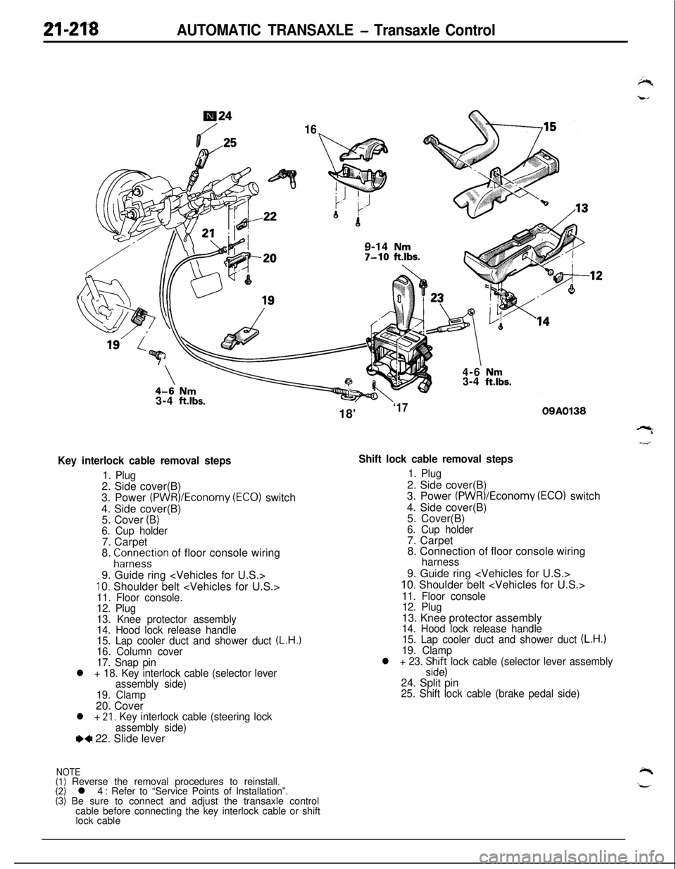
2l-218AUTOMATIC TRANSAXLE - Transaxle Control
724
169-14
Nm7-10 ftlbs.7
\\4-6 Nm3-4 ft.lbs.3-4
ft.lbs.
Key interlock cable removal steps
1. Plug2. Side cover(B)
3. Power
(PWR)/Economy (ECO) switch
4. Side cover(B)
5. Cover
(B)6. Cup holder7. Carpet
8.
;ir;eystion of floor console wiring
9. Guide ring
10. Shoulder belt
12. Plug
13. Knee protector assembly
14. Hood lock release handle
15. Lap cooler duct and shower duct
(L.H.)16. Column cover
17. Snap pin
l + 18. Key interlock cable (selector lever
assembly side)
19. Clamp20. Cover
l + 21, Key interlock cable (steering lock
assembly side)
e+ 22. Slide lever
NOTE(I) Reverse the removal procedures to reinstall.(2) l 4 : Refer to “Service Points of Installation”.(3) Be sure to connect and adjust the transaxle control
cable before connecting the key interlock cable or shift
lock cable18'
‘1709A0138
Shift lock cable removal steps
1. Plug2. Side cover(B)
3. Power
(PWR)/Economv (EC01 switch
4. Side cover(B)
’5. Cover(B)
6. Cup holder7. Carpet
8. Connection of floor console wiring
harness9. Guide ring
10. Shoulder belt
11. Floor console
12. Plug13. Knee protector assembly
14. Hood lock release handle
15. Lap cooler duct and shower duct (L.H.)19. Clamp
l + 23. :izs lock cable (selector lever assembly24. Split pin
25. Shift lock cable (brake pedal side)