power steering MITSUBISHI ECLIPSE 1991 Service Manual
[x] Cancel search | Manufacturer: MITSUBISHI, Model Year: 1991, Model line: ECLIPSE, Model: MITSUBISHI ECLIPSE 1991Pages: 1216, PDF Size: 67.42 MB
Page 1 of 1216
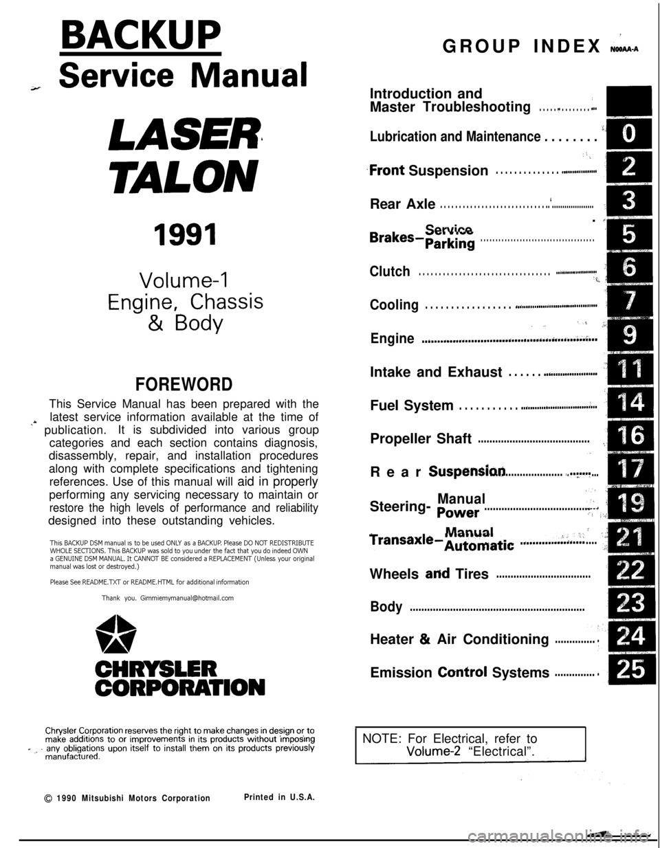
BACKUPGROUP INDEX &ma
;r Service Manual
LASER
TALON
1991
Volume-l
Engine, Chassis
& Body
FOREWORDThis Service Manual has been prepared with the
latest service information available at the time of
‘* publication.It is subdivided into various group
categories and each section contains diagnosis,
disassembly, repair, and installation procedures
along with complete specifications and tightening
references. Use of this manual will aid in properly
performing any servicing necessary to maintain or
restore the high levels of performance and reliabilitydesigned into these outstanding vehicles.
This BACKUP DSM manual IS to be used ONLY as a BACKUP. Please DO NOT REDISTRIBUTEWHOLE SECTIONS. This BACKUP was sold to you under the fact that you do indeed OWNa GENUINE DSM MANUAL. It CANNOT BE considered a REPLACEMENT (Unless your originalmanual was lost or destroyed.)Please See
README.N or README.HTML for additional information
Thank you. G~mm~emymanual@hotma~l.com
1,
wA
CHRYSLER
CORPORATION
Chrysler Corporation reserves the right to make changes in design 0’: tomake additions to or improvements in its products without lmqoslngd ., . any obligations upon itself to install them on its products previouslymanufactured.
0 1990 Mitsubishi Motors CorporationPrinted in U.S.A.Introduction and
Master
Troubleshooting. . . . . .,. . . . . . . . . r...m,
Lubrication and Maintenance . . . . . . . . ‘-0‘8
; “. i,
.Front Suspension. . . . . . . . . . . . . . ..*............d...Rear Axle
. . . . . . . . . . . . . . . . . . . . . . . . . . . . ..‘.....................
/
ServiceBrakes-Parking. . . . . . . . . . . . . . . . . . . . . . . . . . . . . . . . . . . . . .
Clutch. . . . . . . . . . . . . . . . . . . . . . . . . . . . . . . . . ..~......................‘t.
Cooling. . . . . . . . . . . . . . . . . ..i....................................
,., .‘,-,
Engine..i....~....r...............~....~.*,.~.~.~,‘~~...;..~~..Intake and Exhaust
. . . . . . ..L....................Fuel System
. . . . . . . . . . . ..ti.......r................~...Propeller Shaft
.......................................IRear
Suspensiori.............................y.f...
ManualSteering- Power.....................................Manual
I
transaxle-Automatic .............:;i...,;.....;Wheels
and Tires.................................
Body.............................................................Heater & Air Conditioning
..............Emission
Contr6l Systems..............
INOTE: For Electrical, refer toVolume-2 “Electrical”.
Page 31 of 1216
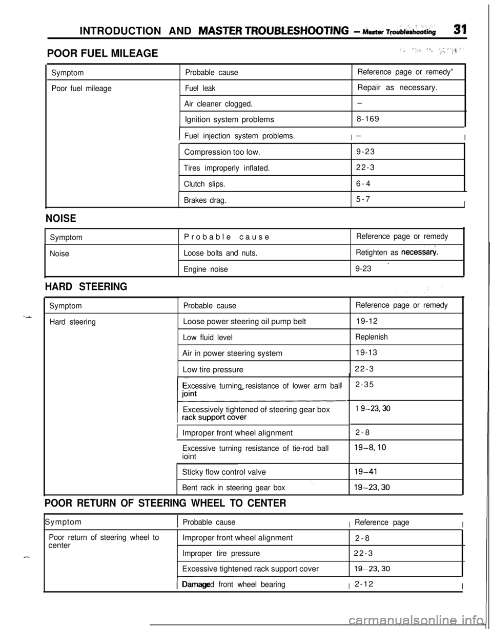
INTRODUCTION AND MASTER TROUBLESH’OOTING .- Master ~pAi&oOti~31POOR FUEL MILEAGE
../, *,, /S./..‘, _I, #_.a,‘.rr?
Symptom
Poor fuel mileageProbable cause
Fuel leak
Air cleaner clogged.Ignition system problems
Reference page or remedy”Repair as necessary.
-8-169
IFuel injection system problems.I-ICompression too low.9-23
Tires improperly inflated.22-3
Clutch slips.6-4
Brakes drag.5-7I
NOISE
Symptom
NoiseProbable cause
Loose bolts and nuts.
Engine noiseReference page or remedy
Retighten as necessary
9-23
’
HARD STEERING
Symptom
Hard steeringProbable causeLoose power steering oil pump belt
Low fluid levelAir in power steering system
Low tire pressure
Reference page or remedy19-12
Replenish19-13
22-3
Excessive turning resistance of lower arm ballExcessively tightened of steering gear box
IImproper front wheel alignment2-8
Excessive turning resistance of tie-rod ballioint2-35
1 i-23.30
19-8.10Sticky flow control valve
Bent rack in steering gear box‘.19-4119-23.30
POOR RETURN OF STEERING WHEEL TO CENTERSymptom
1Probable causeIReference pageI
Poor return of steering wheel tocenterImproper front wheel alignment
2-8
Improper tire pressure22-3
Excessive tightened rack support cover19-23.30
I-- ~~~Damaged front wheel bearingI2-12I
Page 38 of 1216
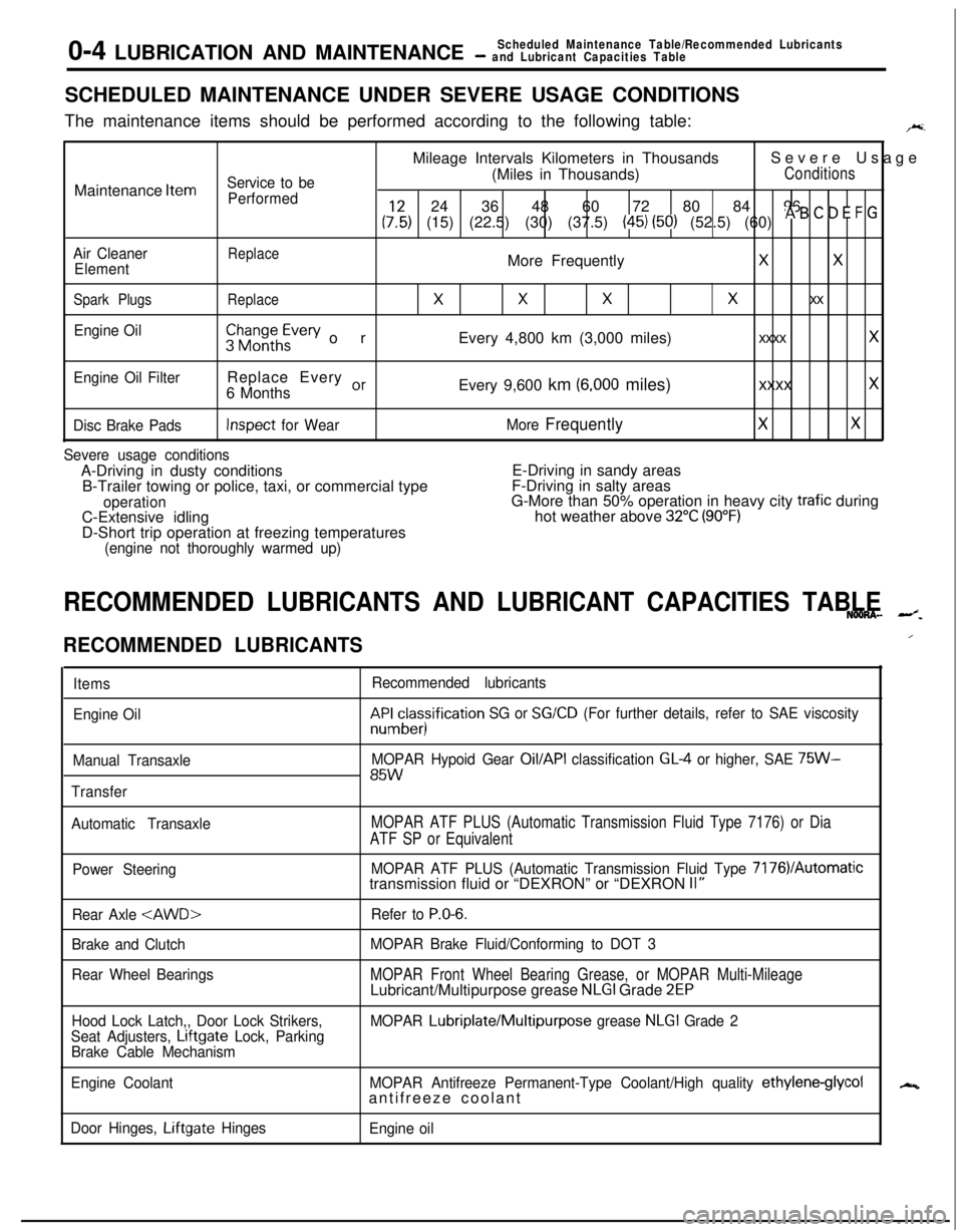
0-4 LUBRICATION AND MAINTENANCEScheduled Maintenance Table/Recommended Lubricants- and Lubricant Capacities TableSCHEDULED MAINTENANCE UNDER SEVERE USAGE CONDITIONS
The maintenance items should be performed according to the following table:
F.Mileage Intervals Kilometers in ThousandsSevere Usage
Service to be(Miles in Thousands)ConditionsMaintenance
Item
Performed24 36 48 60 72 80 84 96
(:,:) (15) (22.5) (30) (37.5) (45) (50) (52.5) (60) * B ’ D E F G
Air CleanerReplaceElementMore FrequentlyXX
Spark PlugsReplace
XXXx xx
Engine Oil$$~~~h~vev orEvery 4,800 km (3,000 miles)xxxx x
Engine Oil FilterReplace Every or6 MonthsEvery 9,600 km (6,000 miles)xxxx x
Disc Brake PadsInspect for WearMore FrequentlyXX
Severe usage conditionsA-Driving in dusty conditionsE-Driving in sandy areas
B-Trailer towing or police, taxi, or commercial typeF-Driving in salty areas
operationG-More than 50% operation in heavy city trafic during
C-Extensive idlinghot weather above 32°C (90°F)D-Short trip operation at freezing temperatures
(engine not thoroughly warmed up)
RECOMMENDED LUBRICANTS AND LUBRICANT CAPACITIES TABLENOONA- --z.
RECOMMENDED LUBRICANTS
Items
Engine Oil
Manual Transaxle
TransferRecommended lubricantskF&cesisification
SG or SG/CD (For further details, refer to SAE viscosity
MOPAR Hypoid Gear
Oil/API classification GL4 or higher, SAE 75W-85W
Automatic TransaxleMOPAR ATF PLUS (Automatic Transmission Fluid Type 7176) or Dia
ATF SP or Equivalent
Power SteeringMOPAR ATF PLUS (Automatic Transmission Fluid Type 7176VAutomatictransmission fluid or “DEXRON” or “DEXRON II”
Rear Axle
Brake and Clutch
Rear Wheel BearingsRefer to
P.O-6.
MOPAR Brake Fluid/Conforming to DOT 3
MOPAR Front Wheel Bearing Grease, or MOPAR Multi-MileageLubricant/Multipurpose grease NLGI Grade 2EP
Hood Lock Latch,, Door Lock Strikers,
Seat Adjusters, Lrftgate Lock, Parking
Brake Cable MechanismMOPAR Lubriplate/Multipurpose grease NLGI Grade 2
Engine CoolantMOPAR Antifreeze Permanent-Type Coolant/High quality
ethylene-glycolantifreeze coolant
Door Hinges, Liftgate Hinges
Engine oil
/
N
Page 39 of 1216
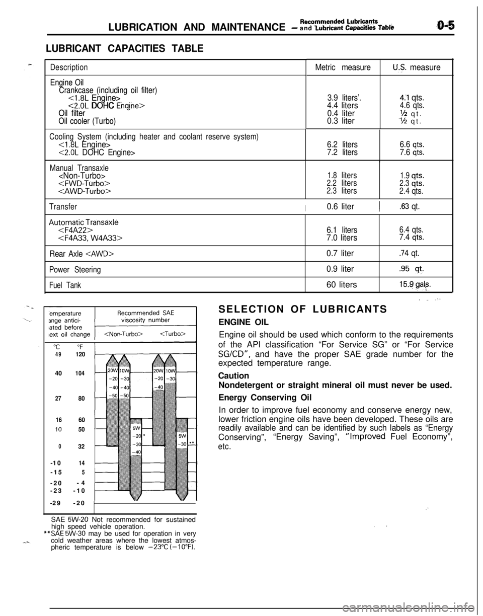
LUBRICATION AND MAINTENANCE - Recommended Lubrie’ntsand Lubrtcant Capacttles Table
LUBRICANT CAPACITIES TABLE
Description
Engine Oil Engine Oil
Crankcase (including oil filter) Crankcase (including oil filter)
<1.8L Engine><1.8L Engine><2.0L DOHC Engine><2.0L DOHC Enaine>Oil filter Oil filter
Oil cooler (Turbo) Oil cooler (Turbo)
Metric measureU.S. measure
3.9 liters’.4.4 liters
0.4 liter
0.3 liter
4.‘1 qts.4.6 qts.
‘h qt.Y2 qt.
Cooling System (including heater and coolant reserve system)
<2.0L DOHC Engine>6.2 liters
7.2 liters6.6
qts.
7.6 qts.
Manual Transaxle
1.8liters1.9qts.2.2liters2.3qts.
2.3liters
2.4qts.
Transfer
I0.6 literI.63 qt.
Au:oFmqaAtF2pnsaxle
Rear Axle
Power Steering
Fuel Tank
"C“F4912040
104
27
80
1660
1050
032-10
14-15
5-20-4
-23-10
-29-20
6.1 liters6.4 qts.
7.0 liters7.4 qts.
0.7 liter.74 qt.
0.9 liter.95 sf.60 liters
15.9 gal?.
’ ~ “.SELECTION OF LUBRICANTS
ENGINE OIL
Engine oil should be used which conform to the requirements
of the API classification “For Service SG” or “For Service
SGKD”, and have the proper SAE grade number for the
expected temperature range.
Caution
Nondetergent or straight mineral oil must never be used.
Energy Conserving Oil
In order to improve fuel economy and conserve energy new,
lower friction engine oils have been developed. These oils are
readily available and can be identified by such labels as “EnergyConserving”,“Energy Saving”,“Improved Fuel Economy”,
etc.
/”SAE
5W-20 Not recommended for sustained
high speed vehicle operation.**SAE
5W-30 may be used for operation in very
cold weather areas where the lowest atmos-
pheric temperature is below
-23°C (-10°F).
Page 92 of 1216
2-44FRONT SUSPENSION -Centermember and Crossmember
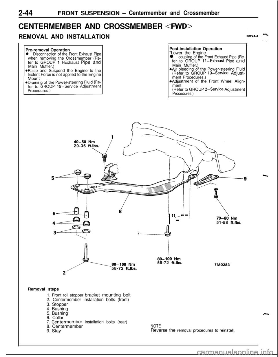
CENTERMEMBER AND CROSSMEMBER
REMOVAL AND INSTALLATION
Pre-removal Operation
l Disconnection of the Front Exhaust Pipewhen removing the Crossmember (Re-
fer to GROUP 1 l-Exhaust Pipe and
Main Muffler.)
@Raise and Suspend the Engine to the
Extent Force is not applied to the EnginePost-installation Operation
*Lower the Enginel coupling of the Front Exhaust Pipe (Re-fer to GROUP ll-Exhaust Pipe and
Main Muffler.)
@Air bleeding of the Power-steering Fluid
(Refer to GROUP 19-Service Adjust-
ment Procedures.)*Adjustment of the Front Wheel Align-
ment
(Refer to GROUP
2-Service AdjustmentProcedures.)
40-50 Nm
29-36 ft.lbs.
! *J
I”---
7
9
80-100 Nm
58-72 ft.lbs.
\80-100 Nm
58-72 ft.lbs.
70-86 Nm
51-58 ft.lbs.llA0283
Removal steps
1. Front roll stopper bracket mounting bolt
2. Centermember installation bolts (front)3. Stopper
4. Bushing
5. Bushing
6. Collar7. Centermember installation bolts (rear)
8. Centermember
9. StayNOTEReverse the removal procedures to reinstall.
4
Page 94 of 1216
2-46FRONT SUSPENSION - Centermember and Crossmember
15-20 Nm
11-14 ft.lbs.12-18
Nm9- 13ft.lbs.9-14
Nm7-10 ft.lbs.
60-60 Nm
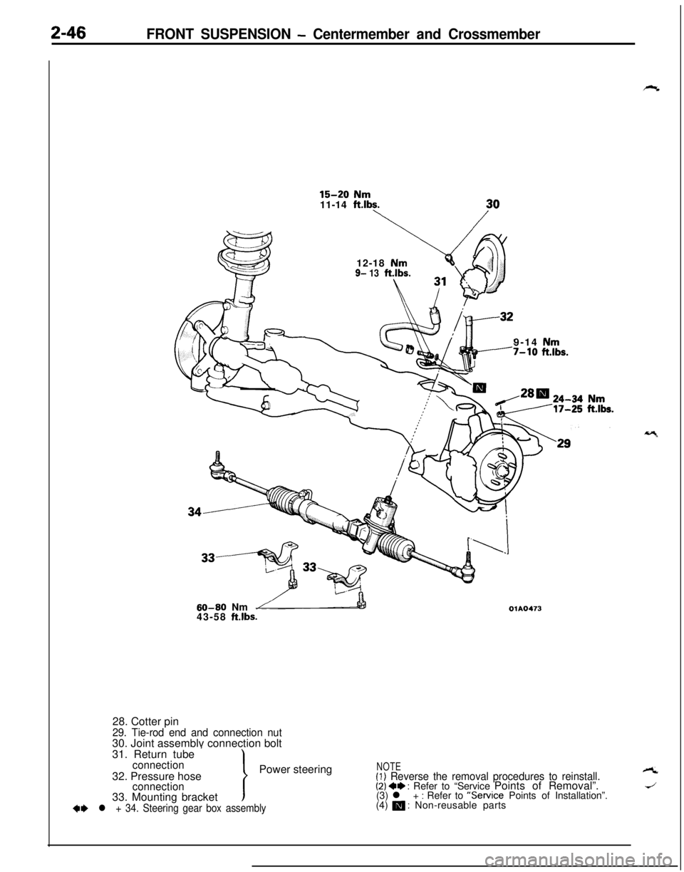
43-58 ft.lbs.OlA047328. Cotter pin
29. Tie-rod end and connection nut30. Joint assemblv connection bolt
31. Return tube
’connectionPower steering
32. Pressure hose
connection33. Mounting bracket
+e l + 34. Steering gear box assembly
NOTE(1) Reverse the removal procedures to reinstall.A
(2) 4+ : Refer to “Service Points of Removal”.J(3) l + : Refer to “Service Points of Installation”.
(4) m : Non-reusable parts
Page 97 of 1216
FRONT SUSPENSION - Centermember and Crossmember2-49
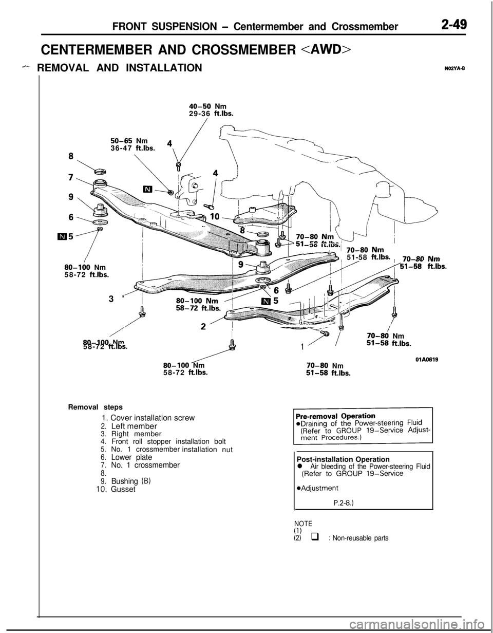
CENTERMEMBER AND CROSSMEMBER
- REMOVAL AND INSTALLATIONNOZYA-B
40-50 Nm
29-36 ft.lbs.
50-65 Nm
36-47 ft.lbs.
\
80-I:0 Nm
58-72 ft.lbs.3'
/I-Y--
7t
/70-80Nm80-100 Nm151-58ft.lbs.58-72 ft.lbs.OlA0619
80-100 Nm70-80Nm58-72 ftlbs.51-58ftlbs.
-30 ll.l”S.,
e ~
70-80 Nm51-58
ft.lbs.7n-~0 NmI” .s- .w...51-58 ft.lbs.Removal steps
1. Cover installation screw
2.Left member3.Right member
4. Front roll stopper installation bolt
5.No. 1 crossmember
installation
nut
6.Lower plate7.No. 1 crossmember
8.
9.Bushing (B)10.GussetPost-installation Operation
l Air bleeding of the Power-steering Fluid(Refer to GROUP 19-Service
*Adjustment
P.2-8.)
NOTE
(I)(2) q : Non-reusable parts
Page 265 of 1216
COOLING - Water Pump <1.8L Engine>
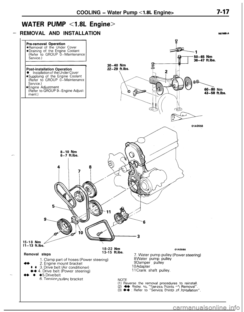
WATER PUMP 4.8L Engine>
7-17
- REMOVAL AND INSTALLATION
c.
-_*Draining of
the Engine Coolant(Refer to GROUP O-Maintenance
Post-installation Operation
l installation of the Under Cover@Supplying of the Engine Coolant(Refer to GROUP O-MaintenanceService.)@Engine Adjustment(RR:; to GROUP g-Engine Adjust-
8-10 Nm6-7 ftlbs.
48NOlMB-A
30-40 Nm
22-2g Fbs.
0
60-80 Nm43-58 ft.lbs.5-18
Nm1-13 ft.lbs.18-22 NmRemoval steps13-15 ft.lbs.
1. Clamp part of hoses (Power steering)4+2. Engine mount bracketl +3. Drive belt (Air conditioner)I)+ 4. Drive belt (Power steering)
4+ l + 5. Drive belt
7. Water pump pulleyWater pump pulleyDamper pullevAdapter. ’Crank shaft pulley.
OlAO566
(Powersteering)
6. Tension tx~llev bra&&I\lnTFr--‘--I -‘--‘.--I.VIL(I) Reverse the removal procedures to reinstall.I?\ CI Refer tn “Smvirr rh:-*- -‘ D---./al”,\-, --. I.VIw, .”..-..,u; r”llllb “I “allI”\(3) +4 : Refer to “Service Points nf Instalk_ - .,.__ -. _.._ .-Jion”.
Page 268 of 1216
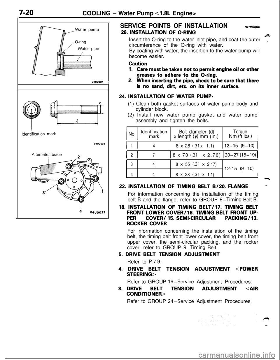
7-20COOLING - Water Pump <1.8L Engine>
aWater pump*<
l-----r,//
O-ringWater
pipe
04ROO24Identification
mark04lJoo25Alternater
brace
404uoo22
J
SERVICE POINTS OF INSTALLATIONN07ME40a
26. INSTALLATION OF O-RINGsInsert the O-ring to the water inlet pipe, and coat the,buter
circumference of the O-ring with water.,
By coating with water, the insertion to the water pump will
become easier.
Caution
1.Care must be taken not to permit engine oil or other
greases to adhere to the O-ring.
2.When inserting the pipe, check to be sure,that there
is no sand, dirt, etc. on its inner surface.
24. INSTALLATION OF WATER PUMP,
(1) Clean both gasket surfaces of water pump body and
cylinder block.
(2) Install new water pump gasket and water pump
assembly and tighten the bolts.
Bolt diameter (d)Torque
x length (e) mm (in.)Nm (ftlbs.)I
I I148 x 28 (.31 x 1.1)112-15 (9-10) 1
I I2
71 8 x 70 (.31 x 2.76) 120-27 (15-19)(
348x55(.31x2.17)12-15(9-10)
448x28(.31x1.1)I
22. INSTALLATION OF TIMING BELT B/20. FLANGE-For information concerning the installation of the timing
belt
B and the flange, refer to GROUP g-Timing Belt B.
18. INSTALLATION OF TIMING BELT/l7. TIMING BELT
FRONT LOWER COVER/lG. TIMING BELT FRONT UP-
PERCOVER/ 15. SEMI-CIRCULARPACKING / 13.
ROCKER COVERFor information concerning the installation of the timing
belt, the timing belt front lower cover, the timing belt front
upper cover, the semi-circular packing, and the rocker
cover, refer to GROUP
g-Timing Belt.
5. DRIVE BELT TENSION ADJUSTMENT
Refer to
P.7-9.
4. DRIVE BELT TENSION ADJUSTMENT
Refer to GROUP
19-Service Adjustment Procedures.
3. DRIVEBELTTENSIONADJUSTMENT
Refer to GROUP
24-Service Adjustment Procedures,
Page 269 of 1216
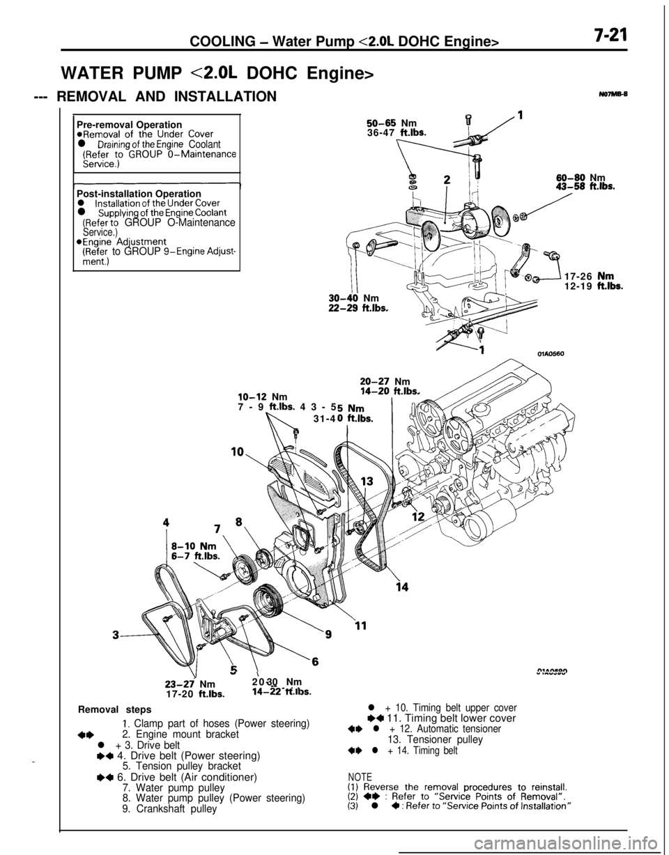
COOLING - Water Pump <2.0L DOHC Engine>7-21WATER PUMP <2.0L DOHC Engine>
--- REMOVAL AND INSTALLATION
No7Ms-B
_Pre-removal Operation
@Removal of the Under Coverl Draining of the Engine Coolant(Refer to GROUP O-MaintenanceService.)
50-65 Nm136-47 ft.lbs.
60-60 Nm
Post-installation Operation
l installation of the Under Coverl supplying of the Engine Coolant(Refer to GROUP O-MaintenanceService.)*Engine Adjustment
(Ri+&; to GROUP g-Engine Adjust-
lo-12 Nm
7-9 ft.lbs. 43-5
31-4
III-40 Nm!-29 ft.lbs.17-26
12-19OlAO560
20-27 Nm14-20 ft.lbs.
23-27 Nm
17-20 ft.lbs.
”20-’ 30 Nm” .““*wY--
-~ . .14-22 ft.ll3s.Removal steps
I. Clamp part of hoses (Power steering)
+*2. Engine mount bracket
l + 3. Drive belte+ 4. Drive belt (Power steering)5. Tension pulley bracket
I)4 6. Drive belt (Air conditioner)7. Water pump pulley
8. Water pump pulley (Power steering)
9. Crankshaft pulley
l + 10. Timing belt upper coverI)4 11. Timing belt lower cover+I) l + 12. Automatic tensioner13. Tensioner pulley
+I) l + 14. Timing belt
NOTE(1) Reverse the removal procedures to reinstall.(2) +e : Refer to “Service Points of Removal”.(3) l 4 : Refer to “Service Points of Installation”
,“k.