ECO mode MITSUBISHI ECLIPSE 1991 Service Manual
[x] Cancel search | Manufacturer: MITSUBISHI, Model Year: 1991, Model line: ECLIPSE, Model: MITSUBISHI ECLIPSE 1991Pages: 1216, PDF Size: 67.42 MB
Page 2 of 1216
2INTRODUCTION AND MASTER TROUBLESHOOTING - How to Use This Manual
HOW TO USE THIS MANUALNOaM
CONTENTSThe preceding page contains GROUP INDEX which
lists the group title and group number.
PAGE NUMBERS
All page numbers consist of two sets of digits
separated by a dash. The digits preceding the dash
identify the
number of the group. The digits follow-
ing the dash represent the consecutive page num-
ber within the group. The page numbers can be
found on the top left or right of each page.
TEXT
Unless otherwise specified, each service procedurecovers all models. Procedures covering specific
models are identified by the model codes, or similar
designation (engine type, transaxle type, etc.). A
description of these designations is covered in this
unit under “VEHICLE IDENTIFICATION”.
TROUBLESHOOTING
Troubleshootings are classified into master trouble-
shooting and group troubleshooting and located as
follows:
The master troubleshooting is prepared when the
trouble symptom relates to two or more groups and
given in MASTER TROUBLESHOOTING.
The group troubleshooting guide is prepared for
causes of problems related to that individual group
only; a troubleshooting guide is prepared for each
appropriate group.LIMIT
-9Shows the standard for judging the quality of a part
-
or assembly on inspection and,means the maximumor minimum value within which the part or assembly
must be kept functionally or in strength.
It is a value
established outside the range of standard value.
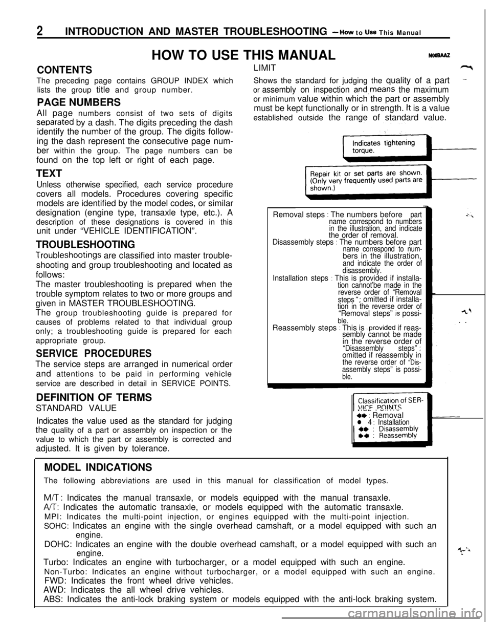
Removal steps
: The numbers beforepartname correspond to numbers
in the illustration, and indicate
the order of removal.
Disassembly steps : The numbers before partname correspond to num-bers in the illustration,
and indicate the order of
disassembly.
Installation steps : This is provided if installa-tion cannot’be made in the
reverse order of “Removal
steps
“; omitted if installa-tion in the reverse order of“Removal steps” k possi-ble.Reassembly steps : This is .provided if reas-sembly cannot be made
rL+. .
in the reverse order of
“Disassemblysteps” ;omitted if reassembly inthe reverse order of “Dis-assembly steps” is possi-ble.
SERVICE PROCEDURESThe service steps are arranged in numerical order
and attentions to be paid in performing vehicle
service are described in detail in SERVICE POINTS.
.IVL, -....-ce : Removall 4 : InstallationDEFINITION OF TERMS
STANDARD VALUEIndicates the value used as the standard for judgingthe quality of a part or assembly on inspection or the
value to which the part or assembly is corrected and
adjusted. It is given by tolerance.
MODEL INDICATIONS
The following abbreviations are used in this manual for classification of model types.
M/T : Indicates the manual transaxle, or models equipped with the manual transaxle.
A/T: Indicates the automatic transaxle, or models equipped with the automatic transaxle.
MPI: Indicates the multi-point injection, or engines equipped with the multi-point injection.
SOHC: Indicates an engine with the single overhead camshaft, or a model equipped with such an
engine.DOHC: Indicates an engine with the double overhead camshaft, or a model equipped with such an
engine.Turbo: Indicates an engine with turbocharger, or a model equipped with such an engine.
Non-Turbo: Indicates an engine without turbocharger, or a model equipped with such an engine.
FWD: Indicates the front wheel drive vehicles.
AWD: Indicates the all wheel drive vehicles.
ABS: Indicates the anti-lock braking system or models equipped with the anti-lock braking system.
Page 27 of 1216
INTRODUCTION AND MASTER TROUBLESHOOTING - f~EEaZ% acld27
=r
9..
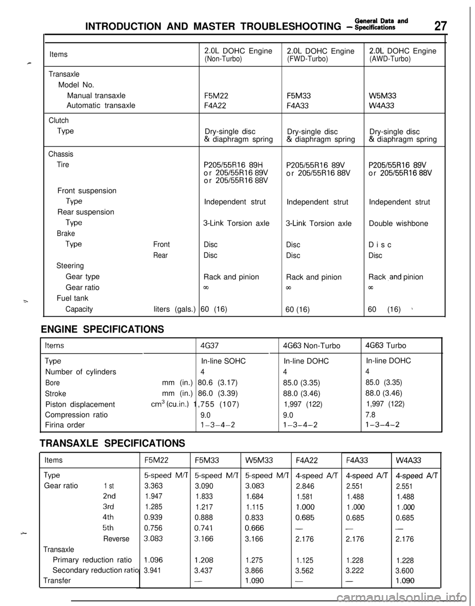
Items
TransaxleModel No.
Manual transaxle
Automatic transaxle
Clutch
Type
Chassis
TireFront suspension
TypeRear suspension
Type
Brake
Type
SteeringGear type
Gear ratio
Fuel tank
Capacity
2.0L DOHC Engine2.0L DOHC Engine2.0L DOHC Engine
(Non-Turbo)(FWD-Turbo)(AWD-Turbo)
F5M22F5M33W5M33
F4A22F4A33W4A33Dry-single disc
Dry-single discDry-single disc& diaphragm spring& diaphragm spring& diaphragm spring
P205/55R16 89HP205155R16 89VP205/55R16 89Vor 205/55R16 89Vor 205/55R16 88Vor 205/55R16 88Vor 205/55R16 88VIndependent strut
Independent strutIndependent strut
3-Link Torsion axle3-Link Torsion axleDouble wishbone
Front
Disc
DiscDisc
RearDisc
DiscDiscRack and pinion
Rack and pinionRack
,and pinion
03coccliters (gals.) 60 (16)
60 (16)60 (16)
)
ENGINE SPECIFICATIONS
Items4G374G63 Non-Turbo4G63 Turbo
TypeIn-line SOHCIn-line DOHCIn-line DOHC
Number of cylinders
444
Boremm (in.) 80.6 (3.17)
85.0 (3.35)85.0 (3.35)
Strokemm (in.) 86.0 (3.39)
88.0 (3.46)88.0 (3.46)
Piston displacement
cm3 (cu.in.) 1,755 (107)1,997 (122)1,997 (122)Compression ratio
9.09.07.8Firina order
1-3-4-21-3-4-21-3-4-2
TRANSAXLE SPECIFICATIONS
ItemsF5M22F5M33W5M33F4A22F4A33W4A33
TypeGear ratio
1 st
2nd
3rd
4th
5th
Reverse
TransaxlePrimary reduction ratio
Secondary reduction
ratio
Transfer
5-speed M/T5-speed M/T
3.363
3.090
1.947
1.833
1.285
1.217
0.939
0.888
0.756
0.741
3.0833.166
5speed M/T4-speed A/T4-speed AIT
3.083
2.8462.551
1.6841.5811.488
1.115
1.0001 .ooo
0.8330.6850.685
0.666--
3.166
2.1762.176
Qspeed AIT
2.551
1.488
1 .ooo
0.685
-
2.176
1.096
3.9411.2081.275
1.1251.2281.228
3.4373.866
3.5623.222
3.600
-1.090--1.090
Page 560 of 1216
14-106ENGINE CONTROL - Service Adjustment Procedures
TAir intakeAdjusting bolts
Idle switch03A,,2.8
07RQ024L
I
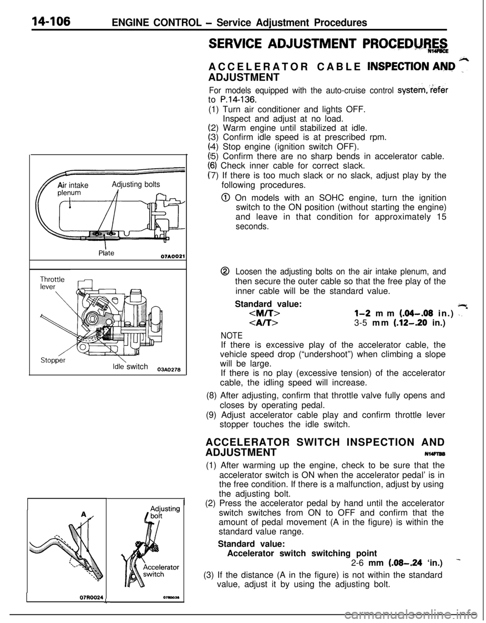
SERVICE ADJUSTMENT PROCEDM%,&ACCELERATOR CABLE
CNSPECTION AN&I ”ADJUSTMENT
For models equipped with the auto-cruise control systemreferto
P.14-136.(1) Turn air conditioner and lights OFF.
Inspect and adjust at no load.
2) Warm engine until stabilized at idle.
3) Confirm idle speed is at prescribed rpm.
4) Stop engine (ignition switch OFF).
5) Confirm there are no sharp bends in accelerator cable.
6) Check inner cable for correct slack.
7) If there is too much slack or no slack, adjust play by the
following procedures.
@ On models with an SOHC engine, turn the ignition
switch to the ON position (without starting the engine)
and leave in that condition for approximately 15
seconds.@
Loosen the adjusting bolts on the air intake plenum, andthen secure the outer cable so that the free play of the
inner cable will be the standard value.
Standard value:
jlr
3-5 mm (.12-.20 in.)
NOTEIf there is excessive play of the accelerator cable, the
vehicle speed drop (“undershoot”) when climbing a slope
will be large.
If there is no play (excessive tension) of the accelerator
cable, the idling speed will increase.
(8) After adjusting, confirm that throttle valve fully opens and
closes by operating pedal.
(9) Adjust accelerator cable play and confirm throttle lever
stopper touches the idle switch.
ACCELERATOR SWITCH INSPECTION AND
ADJUSTMENT
NlWlEB(1) After warming up the engine, check to be sure that the
accelerator switch is ON when the accelerator pedal’ is in
the free condition. If there is a malfunction, adjust by using
the adjusting bolt.
(2) Press the accelerator pedal by hand until the accelerator
switch switches from ON to OFF and confirm that the
amount of pedal movement (A in the figure) is within the
standard value range.
Standard value:
Accelerator switch switching point
2-6 mm
(.08-.24 ‘in.)
(3) If the distance (A in the figure) is not within the standard
value, adjust it by using the adjusting bolt.
Page 570 of 1216
14-116AUTO-CRUISE CONTROL SYSTEM - Troubleshooting
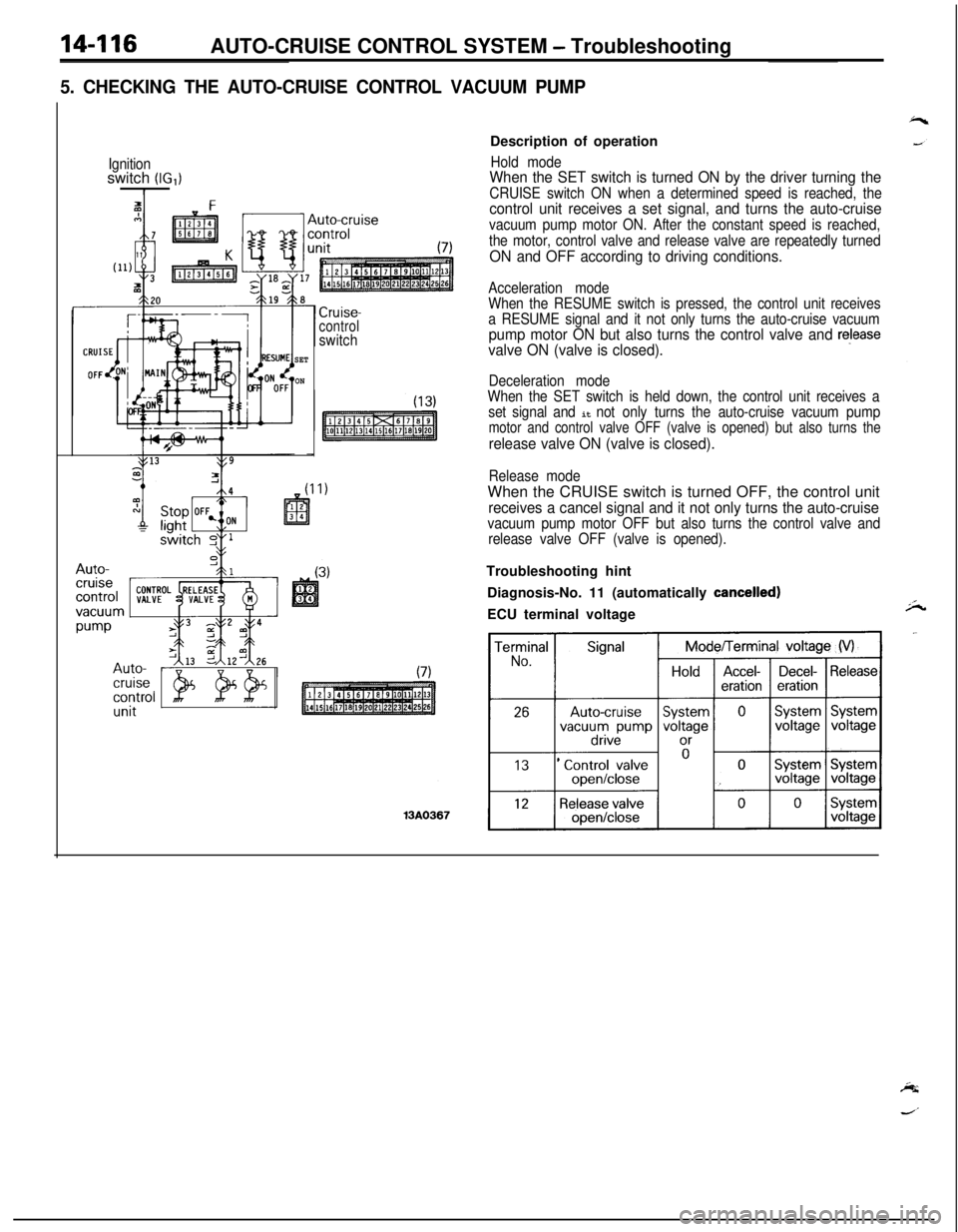
5. CHECKING THE AUTO-CRUISE CONTROL VACUUM PUMP
Ignitionswitch (IG,)I
SET
ON
Cruise-controlswitchDescription of operation
Hold modeWhen the SET switch is turned ON by the driver turning the
CRUISE switch ON when a determined speed is reached, thecontrol unit receives a set signal, and turns the auto-cruise
vacuum pump motor ON. After the constant speed is reached,
the motor, control valve and release valve are repeatedly turned
ON and OFF according to driving conditions.
Acceleration mode
When the RESUME switch is pressed, the control unit receives
a RESUME signal and it not only turns the auto-cruise vacuum
pump motor ON but also turns the control valve and releasevalve ON (valve is closed).
Deceleration mode
When the SET switch is held down, the control unit receives a
set signal and
it not only turns the auto-cruise vacuum pumpmotor and control valve OFF (valve is opened) but also turns the
release valve ON (valve is closed).
Release modeWhen the CRUISE switch is turned OFF, the control unit
receives a cancel signal and it not only turns the auto-cruisevacuum pump motor OFF but also turns the control valve and
release valve OFF (valve is opened).Troubleshooting hint
Diagnosis-No. 11 (automatically
cancelled)ECU terminal voltage
Page 882 of 1216
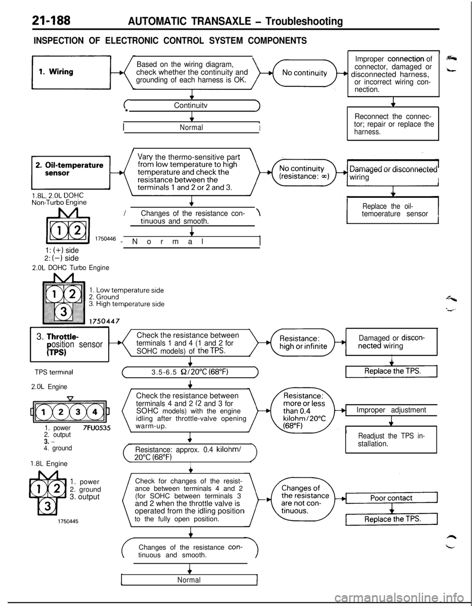
21-188AUTOMATIC TRANSAXLE - Troubleshooting
INSPECTION OF ELECTRONIC CONTROL SYSTEM COMPONENTS
Based on the wiring diagram,check whether the continuity and
grounding of each harness is OK.
+
cContinuitvJ.
4
/
.NormalI
1
Improper connection of
connector, damaged or
+ disconnected harness,or incorrect wiring con-
nection.
L
J1
Reconnect the connec-
tor; repair or replace the
harness.
I\
Vary the thermo-sensitive part
uarriageu ur ursconnecreawiring
I/
IReplace the oil-Chanaes of the resistance con-\temoerature sensortinuo& and smooth.4
I 1750446 -Normal,
1: (+) side2:
(-) side
2.0L DOHC TurboEngine
1I
Y3.
Throttle-Check the resistance betweenosition sensorterminals 1 and 4 (1 and 2 forDamaged or discon-
PTPS)SOHC models) of theTPS.netted wiringI
I
TPS termrnal
2.0L Engine
1. power
7FUO5352. output3. -4. ground
1.8L Engine
1. power
2. ground
3. output
+
(3.5-6.5 S2/2O”C (68°F)1Check the resistance between
terminals 4 and 2 (2 and 3 forSOHC models) with the engine
idling after throttle-valve opening
warm-up.
4
Resistance: approx. 0.4 kilohml
20°C (68°F)I
Improper adjustment
J
’Readjust the TPS in-
stallation.Check for changes of the resist-
ance between terminals 4 and 2
(for SOHC between terminals 3
and 2 when the throttle valve is
operated from the idling position
to the fully open position.
4Changes of the resistance con-
tinuous and smooth.
4
Normal
Page 1150 of 1216
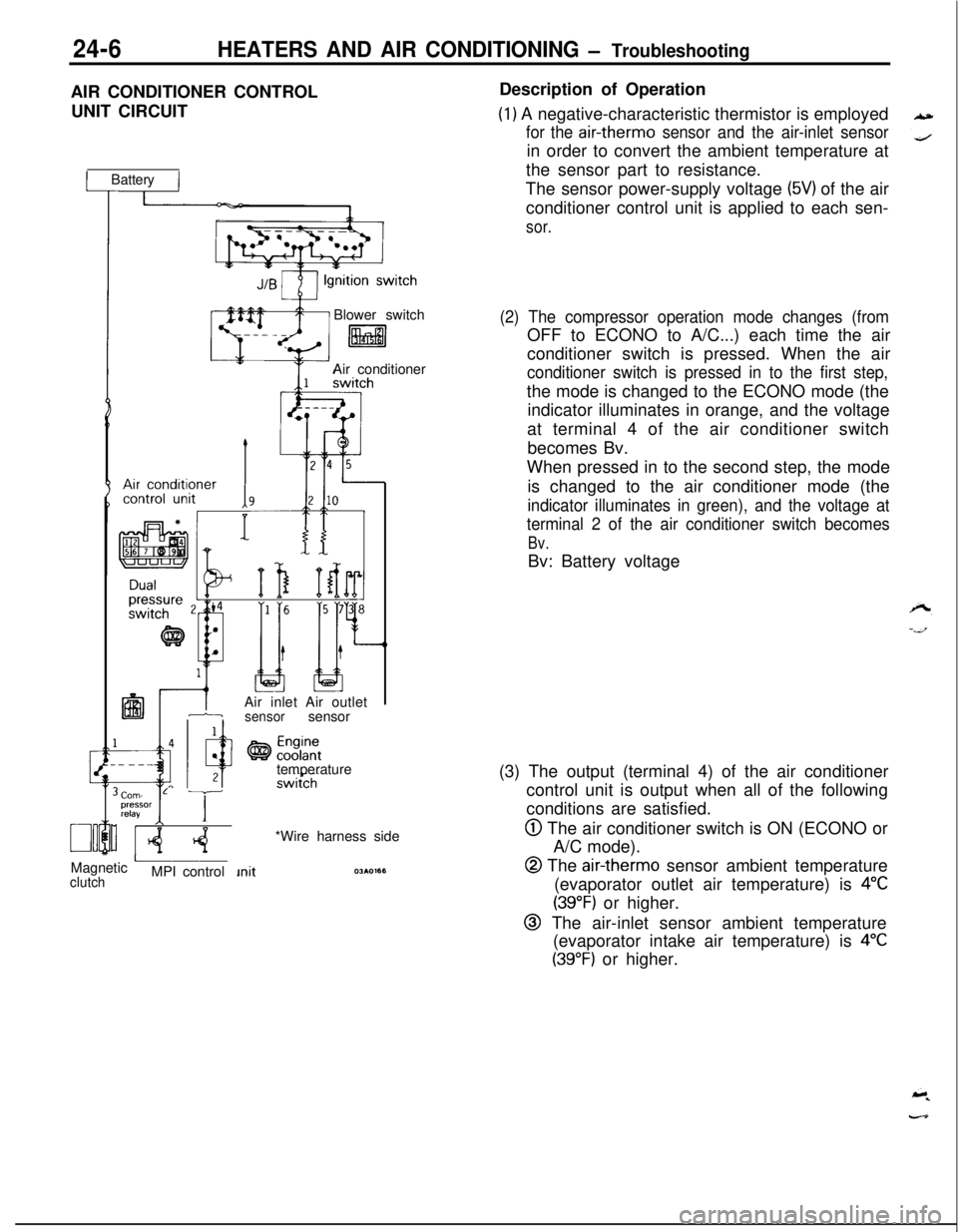
24-6HEATERS AND AIR CONDITIONING - TroubleshootingAIR CONDITIONER CONTROL
UNIT CIRCUIT
1 Battery IBlower switch
litalAir conditioner
IAir inlet Air outlet1-isensorsensor
temperature
Corn- L Tpressor
relayI IMagnetic
AclutchMPI control*Wire harness sideDescription of Operation
(1) A negative-characteristic thermistor is employed
for the air-therm0 sensor and the air-inlet sensorin order to convert the ambient temperature at
the sensor part to resistance.
The sensor power-supply voltage
(5V) of the air
conditioner control unit is applied to each sen-
sor.
(2) The compressor operation mode changes (fromOFF to ECONO to A/C...) each time the air
conditioner switch is pressed. When the air
conditioner switch is pressed in to the first step,the mode is changed to the ECONO mode (the
indicator illuminates in orange, and the voltage
at terminal 4 of the air conditioner switch
becomes Bv.
When pressed in to the second step, the mode
is changed to the air conditioner mode (the
indicator illuminates in green), and the voltage at
terminal 2 of the air conditioner switch becomes
Bv.Bv: Battery voltage
(3) The output (terminal 4) of the air conditioner
control unit is output when all of the following
conditions are satisfied.
@ The air conditioner switch is ON (ECONO or
A/C mode).
@ The air-therm0 sensor ambient temperature
(evaporator outlet air temperature) is
4°C
(39°F) or higher.
@ The air-inlet sensor ambient temperature
(evaporator intake air temperature) is
4°C
(39°F) or higher.
Page 1154 of 1216
24-10HEATERS AND AIR CONDITIONING - Safety Precautions
SAFETY PRECAUTIONSN24PAAD
The refrigerant used in all air conditioner is R-l 2. It istransparent and colorless in both the liquid and
vapor state. Since it has a boiling point of
-29.8”C(-85.6”F).
at atmospheric pressure, it will be a vapor
at all normal temperatures and pressures. The vaporis heavier than air, non-flammable, and nonexplo-
sive. It is nonpoisonous except when it is in direct
contact with open flame. It
ia noncorrosive except
when combined with water. The following precau-
tions must be observed when handling
R-12.Caution
Wear safety goggles when servicing the refriger-ation system.
R-12 evaporates so rapidly at normal atmospheric
pressures and temperatures that it tends to freeze
anything it contacts. For this reason, extreme care
must be taken to prevent any liquid refrigerant from
contacting the skin and especially the eyes. Always
wear safety goggles when servicing the refrigera-
tion part of the air conditioning system. Keep a
bottle of sterile mineral oil handy when working on
the refrigeration system. Should any liquid re-
frigerant get into the eyes, use a few drops of
mineral oil to wash them out.
R-12 is rapidly
absorbed by the oil. Next splash the eyes with
plenty of cold water. Call your doctor immediately
even though irritation has ceased after treatment.
Caution
Do not heat
R-12 above 40°C (104°F).In most instances, moderate heat is required to
bring the pressure of the refrigerant in its container
above the pressure of the system when charging or
adding refrigerant. A bucket or large pan of hot
water not over
40°C (104°F) is all the heat required
for this purpose. Do not heat the refrigerant contain-
er with a blow torch or any other means that would
raise temperature and pressure above this tempera-ture. Do not weld or steam clean on or near the
system components or refrigerant lines.
Caution
Keep
R-12 containers upright when charging the
system.When metering
R-12 into the refrigeration system,
keep the supply tank or cans in an upright position. Ifthe refrigerant container is on its side or upside
down, liquid refrigerant will enter the system and
damage the compressor.Caution
Always work in a well-ventilated room.
‘irrGood ventilation is vital in the working area. Always
discharge the refrigerant into the service bay ex-
haust system or outside the building. Large quanti-
ties of refrigerant vapor in a small, poorly ventilated
room can displace the air and cause suffocation.
Although
R-12 vapor is normally nonpoisonous,
contact with an open flame can cause the vapor to
become very poisonous. Do not discharge large
quantities of refrigerant in an area having an open
flame. A poisonous gas is produced when using theflame-type leak detector. Avoid inhaling the fumes
from the leak detector.
Caution
Do not allow liquid refrigerant to touch bright
metal.
Refrigerant will tarnish bright metal and chrome
surfaces, and in combination with moisture can
severely corrode all metal surfaces.
R-12 Refrigerant Bundling
Refrigerant Recycling
R-12 refrigerant is a chloro-floro-carbon (CFC) that
can contribute to the depletion of the ozone layer in
the upper atmosphere.A
Ozone filters out harmful radiation from the sun.
- -/.To assist in protecting the ozone layer, Mitsubishi
Motors Corporation
recomends that a R-12 re-
frigerant recycling device that meets SAE standard
J1991 be used.
Contact an automotive service equipment supplier
for refrigerant recycling equipment that is available
in your area.
Refer to the operating instructions provided with therecycling equipment for proper operation.
Page 1172 of 1216
24-28HEATERS AND AIR CONDITIONING - Heater Control Assembly
II
IT20AO409
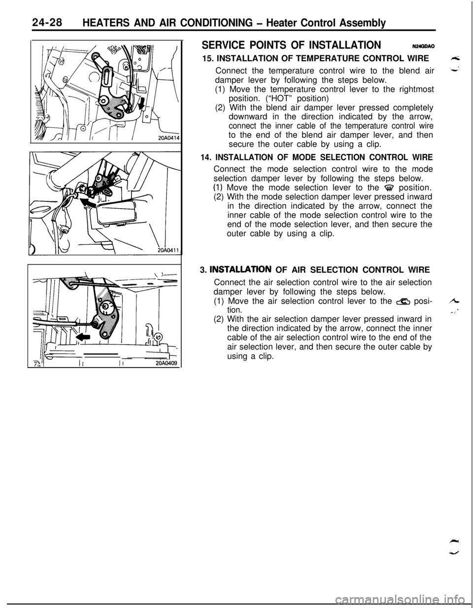
SERVICE POINTS OF INSTALLATIONN24GOAO
15. INSTALLATION OF TEMPERATURE CONTROL WIRE
Connect the temperature control wire to the blend air
damper lever by following the steps below.
(1) Move the temperature control lever to the rightmost
position. (“HOT” position)
(2) With the blend air damper lever pressed completely
downward in the direction indicated by the arrow,
connect the inner cable of the temperature control wireto the end of the blend air damper lever, and then
secure the outer cable by using a clip.
14. INSTALLATION OF MODE SELECTION CONTROL WIREConnect the mode selection control wire to the mode
selection damper lever by following the steps below.
(1) Move the mode selection lever to the $$ position.
(2) With the mode selection damper lever pressed inward
in the direction indicated by the arrow, connect the
inner cable of the mode selection control wire to the
end of the mode selection lever, and then secure the
outer cable by using a clip.
3. INSTALLATlON OF AIR SELECTION CONTROL WIRE
Connect the air selection control wire to the air selection
damper lever by following the steps below.
(1) Move the air selection control lever to the
& posi-
tion.(2) With the air selection damper lever pressed inward in
the direction indicated by the arrow, connect the inner
cable of the air selection control wire to the end of the
air selection lever, and then secure the outer cable by
using a clip.