Starter MITSUBISHI ECLIPSE 1991 Service Manual
[x] Cancel search | Manufacturer: MITSUBISHI, Model Year: 1991, Model line: ECLIPSE, Model: MITSUBISHI ECLIPSE 1991Pages: 1216, PDF Size: 67.42 MB
Page 308 of 1216
9-24ENGINE - Service Adjustment Procedures
ENGINE 4.8L Engine>
SERVICE ADJUSTMENT PROCEDURES -
CHECKING COMPRESSION PRESSURENOSFFAI
(1) Before checking compression, ensure that engine oil, the
starter motor, and battery are all in good condition.
(2) Start the engine and wait until engine coolant temperature
has risen to
85-95°C (185-205°F).
(3) Stop the engine and pull the spark plug cables.
(4) Remove the spark plugs.
(5) Crank the engine to remove any foreign objects in the
cylinders.Caution
Cover the spark plug holes with shop towel, etc., in
order to keep expelled foreign objects from flying out,
and keep away from the holes. When measuring
compression with water, oil, or fuel having entered the
cylinder through a crack, etc., these will come flying
out of the spark plug hole hot and fast, so be sure to
take the proper precautions.
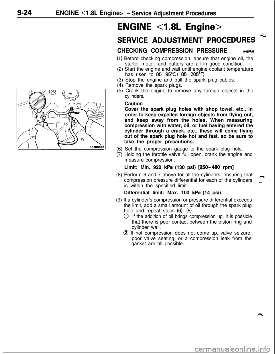
(6) Set the compression gauge to the spark plug hole.
(7) Holding the throttle valve full open, crank the engine and
measure compression.
Limit: Min. 920
kPa (130 psi) [250-400 rpm]
(8) Perform 6 and 7 above for all the cylinders, ensuring that
compression pressure differential for each of the cylinders
/Iis within the specified limit.
__Differential limit: Max. 100
kPa (14 psi)
(9) If a cylinder’s compression or pressure differential exceeds
the limit, add a small amount of oil through the spark plug
hole and repeat steps (6)-(8).
0If the addition of oil brings compression up, it is possiblethat there is poor contact between the piston ring and
cylinder wall.
@ If not compression does not come up, valve seizure,
poor valve seating, or a compression leak from the
gasket are all possible.
/y
-
Page 355 of 1216
ENGINE - Crankshaft, Flwvheel and Drive Plate9-71
3EN30’lrrow mark toward
cap No,
I
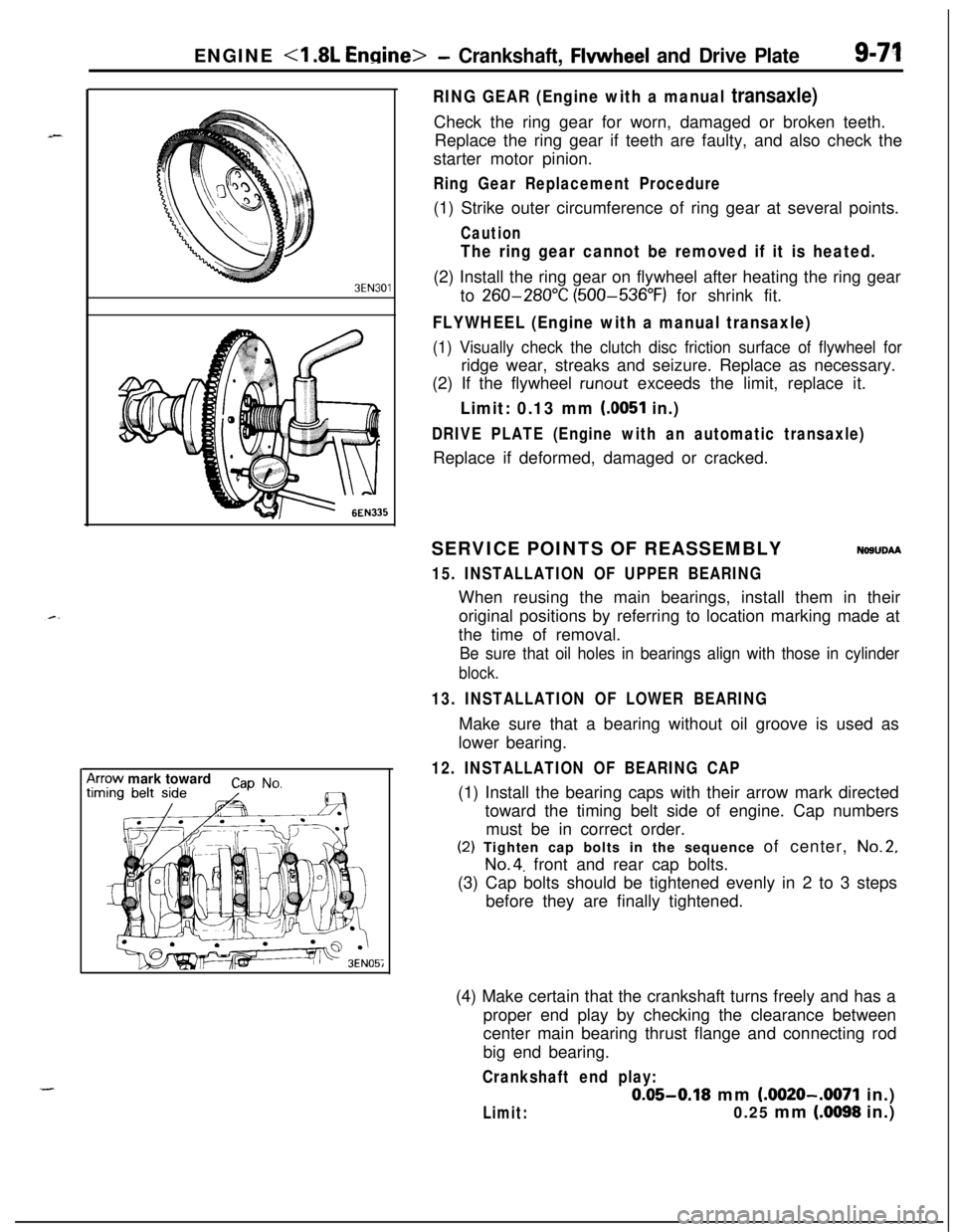
RING GEAR (Engine with a manual transaxle)Check the ring gear for worn, damaged or broken teeth.
Replace the ring gear if teeth are faulty, and also check the
starter motor pinion.
Ring Gear Replacement Procedure(1) Strike outer circumference of ring gear at several points.
Caution
The ring gear cannot be removed if it is heated.(2) Install the ring gear on flywheel after heating the ring gear
to
260-280°C (500-536°F) for shrink fit.
FLYWHEEL (Engine with a manual transaxle)
(1) Visually check the clutch disc friction surface of flywheel forridge wear, streaks and seizure. Replace as necessary.
(2) If the flywheel
runout exceeds the limit, replace it.
Limit: 0.13 mm (0051 in.)
DRIVE PLATE (Engine with an automatic transaxle)Replace if deformed, damaged or cracked.
SERVICE POINTS OF REASSEMBLY
NOSUDAA
15. INSTALLATION OF UPPER BEARINGWhen reusing the main bearings, install them in their
original positions by referring to location marking made at
the time of removal.
Be sure that oil holes in bearings align with those in cylinder
block.
13. INSTALLATION OF LOWER BEARINGMake sure that a bearing without oil groove is used as
lower bearing.
12. INSTALLATION OF BEARING CAP(1) Install the bearing caps with their arrow mark directed
toward the timing belt side of engine. Cap numbers
must be in correct order.(2) Tighten cap bolts in the sequence of center,
No.2,
No.4. front and rear cap bolts.
(3) Cap bolts should be tightened evenly in 2 to 3 steps
before they are finally tightened.
(4) Make certain that the crankshaft turns freely and has a
proper end play by checking the clearance between
center main bearing thrust flange and connecting rod
big end bearing.
Crankshaft end play:
0.05-0.18 mm (.0020-.0071 in.)
Limit:0.25 mm (.0098 in.)
Page 358 of 1216
9-74ENGINE <2.0L DOHC Engine>- Service Adjustment Procedures
ENGINE <2.0L DOHC Engine>
SERVICE ADJUSTMENT PROCEDURES pi
CHECKING COMPRESSION PRESSURENOSFFAH(1) Before checking compression, ensure that engine oil, the
starter motor, and battery are all in good condition.
(2) Start the engine and wait until engine coolant temperature
has risen to
85-95°C (185-205°F).
(3) Stop the engine and pull the spark plug cables.
(4) Remove the spark plugs.
(5) Crank the engine
to. remove any foreign objects in the
cylinders.
Caution
Cover the spark plug holes with shop towel, etc., in
order to keep expelled foreign objects from flying out,and keep away from the holes. When measuring
compression with water, oil, or fuel having entered the
cylinder through a crack, etc., these will come flying
out of the spark plug hole hot and fast, so be sure to
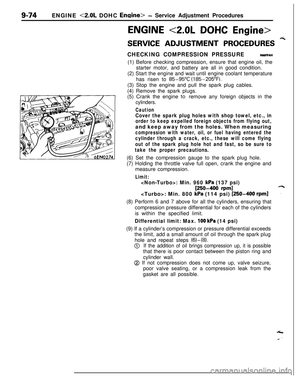
take the proper precautions.(6) Set the compression gauge to the spark plug hole.
(7) Holding the throttle valve full open, crank the engine and
measure compression.
Limit:
[250-400 rpm]6
kPa (114 psi) [250-400 rpml-(8) Perform 6 and 7 above for all the cylinders, ensuring that
compression pressure differential for each of the cylinders
is within the specified limit.
Differential limit: Max. 100 kPa (14 psi)(9) If a cylinder’s compression or pressure differential exceeds
the limit, add a small amount of oil through the spark plug
hole and repeat steps (6)-(8).
@If the addition of oil brings compression up, it is possiblethat there is poor contact between the piston ring and
cylinder wall.
@ If not compression does not come up, valve seizure,
poor valve seating, or a compression leak from the
gasket are all possible.‘I
Page 418 of 1216

g-134 ENGINE <2.0L DOHC Engine>- Crankshaft, Flywheel and Drive Plate
3EN301CRANKSHAFT REAR OIL SEAL
(1) Check oil seal lip for wear and damage.
(2) Check rubber for deterioration or hardening.
(3) Check oil seal case for cracks and damage.
RING GEAR (Engine with a manual transaxle)
Check teeth of ring gear for wear and damage. If necessary,
replace the ring gear.
If the ring gear teeth are worn or damaged, also check the
starter motor pinion.
To remove the ring gear, strike the ring gear at several points
on its outer circumference. The ring gear cannot be removed ifit is heated.
To install the ring gear, heat the ring gear to
300°C (572°F) for
shrink fit.
FLYWHEEL (Engine with a manual transaxle)
(1) Check the clutch disc friction surface for ridge wear,
streaks, and seizure. If necessary, replace flywheel.
(2) If the
runout of flywheel exceeds the limit, replace.++.Limit: 0.13 mm
(.0051 in.)
DRIVE PLATE (Engine with an automatic transaxle)
Replace deformed, damaged, or cracked drive plates.
SERVICE POINTS OF REASSEMBLYNWUGAB
14. INSTALLATION OF CRANKSHAFT BEARING (UPPER)
Install the upper crankshaft bearing to the cylinder block.
There is an oil groove in the upper crankshaft bearing.
There is no difference between upper and lower bearings
for the center (with flange).
12. INSTALLATION OF CRANKSHAFT BEARING (LOWER)
Install the lower crankshaft bearing (with no oil groove;
there is no difference for center) to each bearing cap and
apply engine oil to bearing surfaces.
Page 556 of 1216
14-102FUEL SYSTEM - Fuel Line and Vapor Line
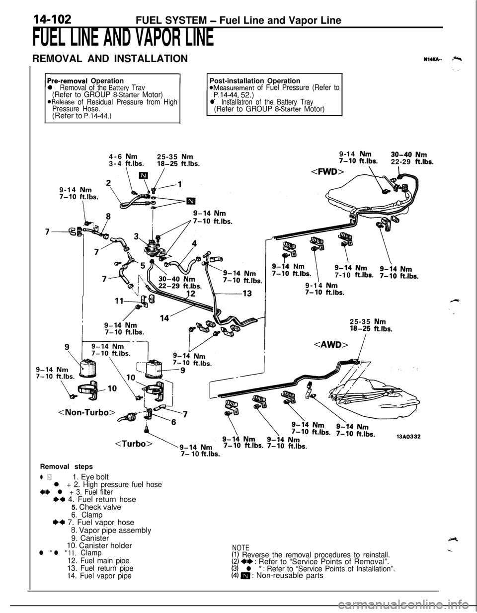
FUEL LINE AND VAPOR LINEREMOVAL AND INSTALLATION
NuKn-
rPre-removal Operationl Removal of the Batten/ Trav(Refer to GROUP 8-Starter Motor)ORelease of Residual Pressure from High
Pressure Hose.(Refer to
P.14-44.)
1Post-installation Operation*Measurement of Fuel Pressure (Refer toP.1444, 52.)l lnstallatron of the Battery Tray(Refer to GROUP 8-Starter Motor)4-6
Nm25-35 Nm3-4 ft.lbs.16-25 ftlbs.9-14 Nm7-10
ftlbs.
I
7-9-14
Nm30-40 Nm7-10 ft.lbs.22-29 ft.lbs.
9-14 Nm
7-10 ftlbs.
9-14Nm7-10 ft.lbs.9-h Nm
7-10ft.lbs.9-i4 Nm7-10ft.lbs.9-14
Nm7- 10ft.lbs.25-35
Nm16-25 ft.lbs.
7-10 ft.lbs. 7-10 ft.lbs.
7- 10 ft.lbs.Removal steps
l *1. Eye boltl + 2. High pressure fuel hose+e l + 3. Fuel filterI)+ 4. Fuel return hose
5. Check valve
6. Clamp~~ 7. Fuel vapor hose
8. Vapor pipe assembly
9. Canister
10. Canister holderl * l * 11.Clamp
12. Fuel main pipe
13. Fuel return pipe
14. Fuel vapor pipe
NOTE(I) Reverse the removal procedures to reinstall.(2) +e : Refer to “Service Points of Removal”.(3) l * : Refer to “Service Points of Installation”.(4) m : Non-reusable parts
Page 571 of 1216
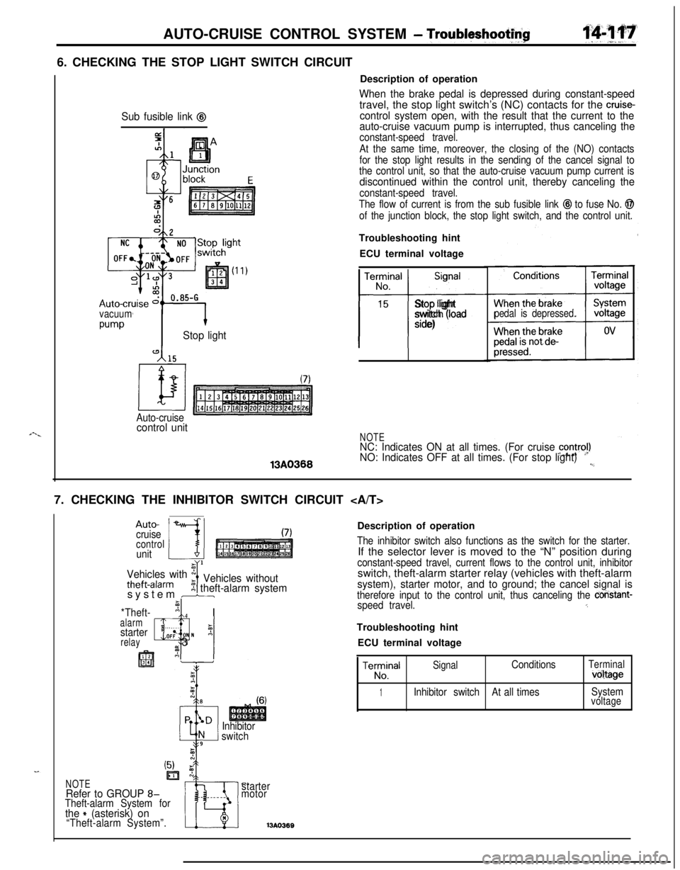
i-._AUTO-CRUISE CONTROL SYSTEM
- Troubltyshootf$6. CHECKING THE STOP LIGHT SWITCH CIRCUIT
Sub fusible link @
vacuum
w-vStop light
Auto-cruisecontrol unit13A0366Description of operation
When the brake pedal is depressed during constant-speedtravel, the stop light switch’s (NC) contacts for the cruise-control system open, with the result that the current to the
auto-cruise vacuum pump is interrupted, thus canceling the
constant-speed travel.
At the same time, moreover, the closing of the (NO) contacts
for the stop light results in the sending of the cancel signal to
the control unit, so that the auto-cruise vacuum pump current is
discontinued within the control unit, thereby canceling the
constant-speed travel.
The flow of current is from the sub fusible link
@I to fuse No. @
of the junction block, the stop light switch, and the control unit.Troubleshooting hint
ECU terminal voltage
TerminalSignal
No.
15
t-i-
Stop light
switch (load
side)pedal is depressed.
NOTENC: Indicates ON at all times. (For cruise contra!)NO: Indicates OFF at all times. (For stop light)l,_7. CHECKING THE INHIBITOR SWITCH CIRCUIT
Auto-
cruise
controlunit
Vehicles with x
theft-alarmIVehicles without5 theft-alarm systemsystem br
*Theft-’ nI Ialarm, ._I
starterz
relayQlOF: N A_ 3
Inhibitor
switchDescription of operation
The inhibitor switch also functions as the switch for the starter.If the selector lever is moved to the “N” position during
constant-speed travel, current flows to the control unit, inhibitorswitch, theft-alarm starter relay (vehicles with theft-alarm
system), starter motor, and to ground; the cancel signal istherefore input to the control unit, thus canceling the constant-speed travel.5Troubleshooting hint
ECU terminal voltage
TeE!alSignalConditionsTerminalvoltage
1Inhibitor switchAt all timesSystemvoltage
C.starter
motor13A036BNOTERefer to GROUP 8-Theft-alarm System forthe + (asterisk) on“Theft-alarm System”.
Page 579 of 1216
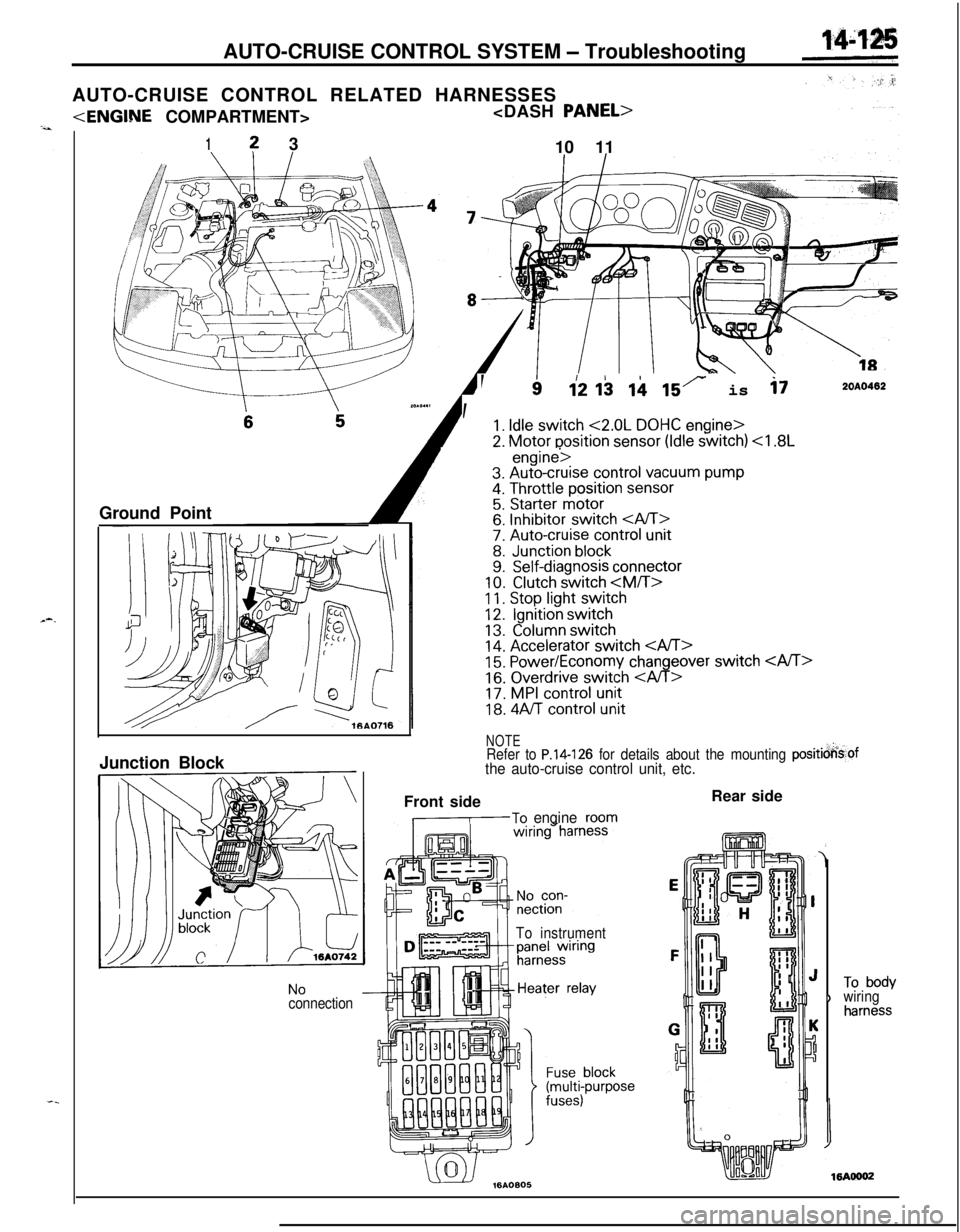
AUTO-CRUISE CONTROL SYSTEM - Troubleshooting
AUTO-CRUISE CONTROL RELATED HARNESSES
1? 3
10 11
Ground Point
--
, ’
112 I$ ii 15r is i72OAO402
1. Idle switch <2.0L DOHC engine>
2. Motor position sensor (Idle switch)
11. Stop light switch12.Ignition switch
13.Column switch14. Accelerator switch 15. Power/Economy changeover switch
16. Overdrive switch
18. 4Aff control unit
NOTERefer to P.14-126 for details about the mounting positicjkof
the auto-cruise control unit, etc.Junction Block
NoconnectionFront side
,-To engineroom
To instrumentRear side
)To bodywiringharness
Page 703 of 1216
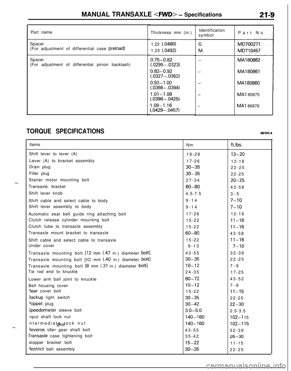
MANUAL TRANSAXLE
Part name
Spacer
(For adjustment of differential case preload)
Spacer
(For adjustment of differential pinion backlash)
TORQUE SPECIFICATIONSThickness mm (in.)
1.22 f.0480)
1.25 (.0492)
0.75-0.82
(.0295-.0323)
0.83-0.92
(.0327-.0362)
0.93- 1 .oo
(.0366-.0394)
1.01-1.08
(.0398-.0425)
1.09-1.16
(.0429-.0457)Identification
symbol
GM
-
-
-
-Part No.
MA180862MA1
80866MA1 80875MA1 86876
Items
Nm
Shift lever to lever (A)
19-28
Lever (A) to bracket assembly
17-26
Drain plug
30-35Filler plug
30-35Starter motor mounting bolt
27-34
Transaxle bracket
60-80Shift lever knob
4.5-7.5
Shift cable and select cable to body9-14
Shift lever assembly to body
9-14
Automatic seat belt guide ring attaching bolt17-26
Clutch release cylinder mounting bolt
15-22
Clutch tube to transaxle assembly
15-22
Transaxle mount bracket to transaxle
60-80Shift cable and select cable to transaxle15-22
Under cover
9-13
Transaxle mounting bolt [12 mm (.47 in.) diameter
bolt143-55
Transaxle mounting bolt [IO mm (.40 in.) diameter
bolt130-35Transaxle mounting bolt
[8 mm (.31 in.) diameter bolt]IO-12Tie rod end to knuckle
24-35
Lower arm ball joint to knuckle
60-72Bell housing cover
IO-123ear cover bolt
15-223ackup light switch
30-35
loppet plug30-42
jpeedometer sleeve bolt3.0-5.0nput shaft lock nut
140-160ntermediate lock nut
gear
140-160
3everse idler gear shaft bolt
43-55
rransaxle case tightening bolt
35-42
stopper bracket bolt
15-22
qestrict ball assembly30-35
ft.lbs.
13-2012-18
22-25
22-25
20-2543-58
3-5
7-10
7-1012-19
11-16
11-1643-58
11-16
7-1032-39
22-25
7-9
17-25
43-52
7-9
11-1522-25
22-302.5-3.5
102-I 15
102-11532-39
26-3011-15
22-25
Page 713 of 1216
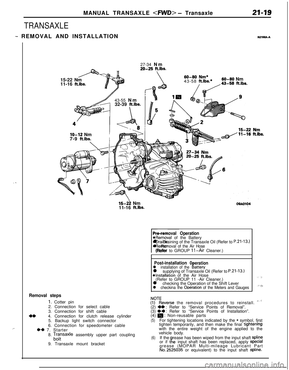
MANUAL TRANSAXLE
TRANSAXLE
- REMOVAL AND INSTALLATIONNZlMA-A
. .
,-27-34 Nm
20-25 ft.lbs.15-22 Nm
11-16
ft.lbs.43-55 Nm
32-39
ft.lbs.
\
60-80 Nm*43-58 ft.lbs.*60-80 Nm
/da-,, ft.lbs.
lo-12 NmI7-9
ft.lbs.I
15-2: Nm
11-16 ft.lbs.OOAOl~4
Pre-removal Operation@Removal of the Battery
rl Draining of the Transaxle Oil (Refer to
P.21-13.)l Removal of the Air Hose(Refer to GROUP 11-Air Cleaner.)
Post-installation 0erationl installation of theI!attery
l supplying of Transaxle Oil (Refer to P.21-13.)*Installation of the Air Hose
(Refer to GROUP 11 -Air Cleaner.)
l checking the Operation of the Shift Lever
l checkina the Ooeration of the Meters and Gauges
Removal steps
1. Cotter pin
2. Connection for select cable
3. Connection for shift cable
4*4. Connection for clutch release cylinder
5. Backup light switch connector
6. Connection for speedometer cable
I)* 7. Starter
8.
Lfrsaxle assembly upper part coupling
9. Transaxle mount bracket
ZKeverse the removal procedures to reinstall. ” ’(2) W : Refer to “Service Points of Removal”.
(3) ~~ : Refer to “Service Points of Installation”.
(4) m : Non-reusable parts
(5)For tightening locations indicated by the * symbol, fjrst
tighten temporarily, and then make the final tightenrngwith the entire weight of the engine applied to the
vehicle body.
(6)If therease has been wiped from the input shaft spline
or if taeinput shaft has been replaced, apply specralgrease (MOPAR Multi-mileage Lubricant Part
No.2525035 or equivalent) to the input shaft Spline.
Page 716 of 1216
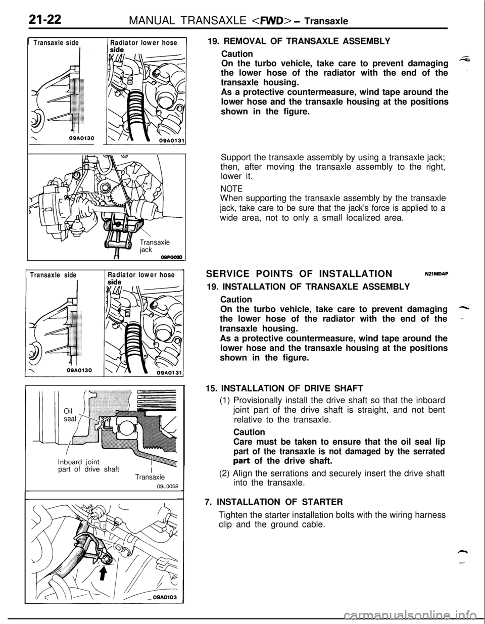
21-22MANUAL TRANSAXLE
1 Transaxleside1 Radiator lower hose
1 Transaxle side1 Radiator lower hosepart ofdrive shaft
I
-Transaxle
09LOO5819. REMOVAL OF TRANSAXLE ASSEMBLY
Caution
On the turbo vehicle, take care to prevent damaging
+Gthe lower hose of the radiator with the end of the
’transaxle housing.
As a protective countermeasure, wind tape around the
lower hose and the transaxle housing at the positions
shown in the figure.
Support the transaxle assembly by using a transaxle jack;
then, after moving the transaxle assembly to the right,
lower it.
NOTEWhen supporting the transaxle assembly by the transaxle
jack, take care to be sure that the jack’s force is applied to awide area, not to only a small localized area.
SERVICE POINTS OF INSTALLATION
NZlMDAP19. INSTALLATION OF TRANSAXLE ASSEMBLY
Caution
On the turbo vehicle, take care to prevent damaging
Athe lower hose of the radiator with the end of the
-transaxle housing.
As a protective countermeasure, wind tape around the
lower hose and the transaxle housing at the positions
shown in the figure.
15. INSTALLATION OF DRIVE SHAFT
(1) Provisionally install the drive shaft so that the inboard
joint part of the drive shaft is straight, and not bent
relative to the transaxle.
Caution
Care must be taken to ensure that the oil seal lip
part of the transaxle is not damaged by the serratedpart of the drive shaft.
(2) Align the serrations and securely insert the drive shaft
into the transaxle.
7. INSTALLATION OF STARTER
Tighten the starter installation bolts with the wiring harness
clip and the ground cable.