ESP MITSUBISHI ECLIPSE 1991 Service Manual
[x] Cancel search | Manufacturer: MITSUBISHI, Model Year: 1991, Model line: ECLIPSE, Model: MITSUBISHI ECLIPSE 1991Pages: 1216, PDF Size: 67.42 MB
Page 2 of 1216
2INTRODUCTION AND MASTER TROUBLESHOOTING - How to Use This Manual
HOW TO USE THIS MANUALNOaM
CONTENTSThe preceding page contains GROUP INDEX which
lists the group title and group number.
PAGE NUMBERS
All page numbers consist of two sets of digits
separated by a dash. The digits preceding the dash
identify the
number of the group. The digits follow-
ing the dash represent the consecutive page num-
ber within the group. The page numbers can be
found on the top left or right of each page.
TEXT
Unless otherwise specified, each service procedurecovers all models. Procedures covering specific
models are identified by the model codes, or similar
designation (engine type, transaxle type, etc.). A
description of these designations is covered in this
unit under “VEHICLE IDENTIFICATION”.
TROUBLESHOOTING
Troubleshootings are classified into master trouble-
shooting and group troubleshooting and located as
follows:
The master troubleshooting is prepared when the
trouble symptom relates to two or more groups and
given in MASTER TROUBLESHOOTING.
The group troubleshooting guide is prepared for
causes of problems related to that individual group
only; a troubleshooting guide is prepared for each
appropriate group.LIMIT
-9Shows the standard for judging the quality of a part
-
or assembly on inspection and,means the maximumor minimum value within which the part or assembly
must be kept functionally or in strength.
It is a value
established outside the range of standard value.
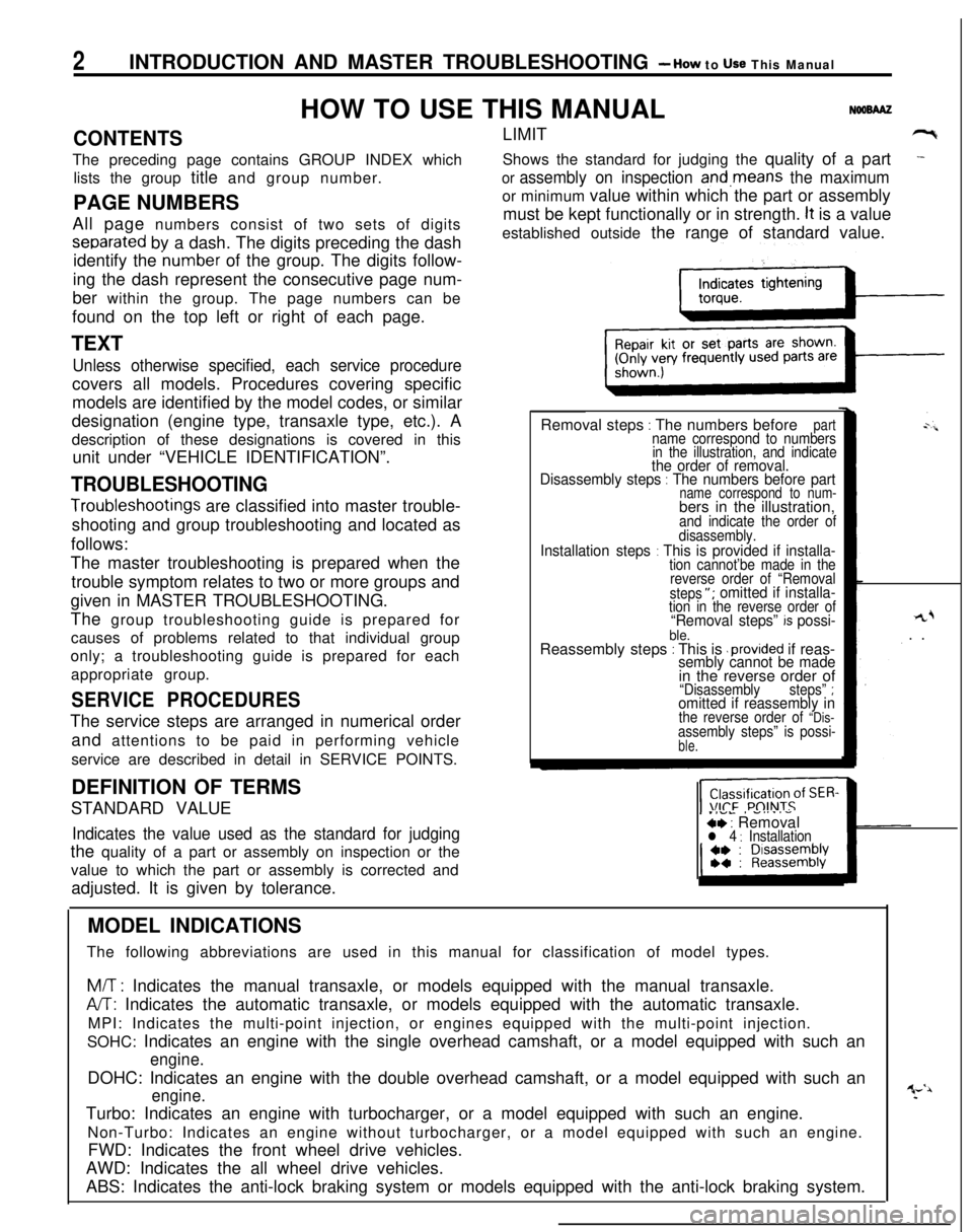
Removal steps
: The numbers beforepartname correspond to numbers
in the illustration, and indicate
the order of removal.
Disassembly steps : The numbers before partname correspond to num-bers in the illustration,
and indicate the order of
disassembly.
Installation steps : This is provided if installa-tion cannot’be made in the
reverse order of “Removal
steps
“; omitted if installa-tion in the reverse order of“Removal steps” k possi-ble.Reassembly steps : This is .provided if reas-sembly cannot be made
rL+. .
in the reverse order of
“Disassemblysteps” ;omitted if reassembly inthe reverse order of “Dis-assembly steps” is possi-ble.
SERVICE PROCEDURESThe service steps are arranged in numerical order
and attentions to be paid in performing vehicle
service are described in detail in SERVICE POINTS.
.IVL, -....-ce : Removall 4 : InstallationDEFINITION OF TERMS
STANDARD VALUEIndicates the value used as the standard for judgingthe quality of a part or assembly on inspection or the
value to which the part or assembly is corrected and
adjusted. It is given by tolerance.
MODEL INDICATIONS
The following abbreviations are used in this manual for classification of model types.
M/T : Indicates the manual transaxle, or models equipped with the manual transaxle.
A/T: Indicates the automatic transaxle, or models equipped with the automatic transaxle.
MPI: Indicates the multi-point injection, or engines equipped with the multi-point injection.
SOHC: Indicates an engine with the single overhead camshaft, or a model equipped with such an
engine.DOHC: Indicates an engine with the double overhead camshaft, or a model equipped with such an
engine.Turbo: Indicates an engine with turbocharger, or a model equipped with such an engine.
Non-Turbo: Indicates an engine without turbocharger, or a model equipped with such an engine.
FWD: Indicates the front wheel drive vehicles.
AWD: Indicates the all wheel drive vehicles.
ABS: Indicates the anti-lock braking system or models equipped with the anti-lock braking system.
Page 3 of 1216
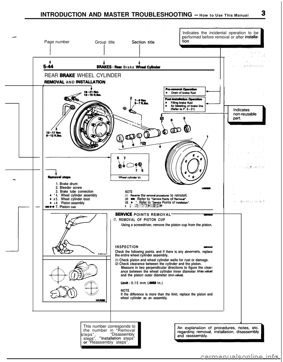
INTRODUCTION AND MASTER TROUBLESHOOTING - How to Use This Manual3Page number
Group title
IIndicates the incidental operation to be
performed before removal or after
installa-
52444BRAKES-Roar Brake Wlmd Cylinder
REAR BRAKE WHEEL CYLINDER
-
-
-
3ENjOVAL AND lNSTAU.AllONII
Remwal stepa
1. Brake drum
2. Bleeder screw
3. Brake tube connectionl * 4.Wheel cylinder assemblyl e 5.Wheel cylinder bootl + 6.Piston assemblyn** 7. Piston cue
NOTEI1 lReverse the removal procedures to reinstall.12)M : Refer to ‘Service Points of Aemcval”.(3)l * : Refer to ‘Service Points of Installation’.14) q :Nc+-r-reusab(epatts
SERWE POINTS REMOVAL’
-7. REMOVAL OF PISTON CUP
Using a screwdriver, remove the piston cup from the piston.
INSPECTION-
Check the following points. and if there is any abnormality, replacethe entire wheel cylinder assembly.
(1) Check piston and wheel cylinder walls for rust or damage.(2) Check clearance between the cylinder and the piston.
Measure in two perpendicular directions to figure the clear-
ance between the wheel cylinder inner diameter
fmax.value)and the piston outer diameter (minvalue).
Limit : 0.15 mm (4059 in.)
NOTE
If the difference is more than the limit, replace the piston and
wheel cylinder as an assembly.This number corresponds to
the number in “Removal
steps”,“Disassembly
steps”,“Installation steps”
or “Reassembly steps”.
Page 4 of 1216
4INTRODUCTION AND MASTER TROUBLESHOOTING - How to use This ManualEXPLANATION OF THE TROUBLESHOOTING GUIDE
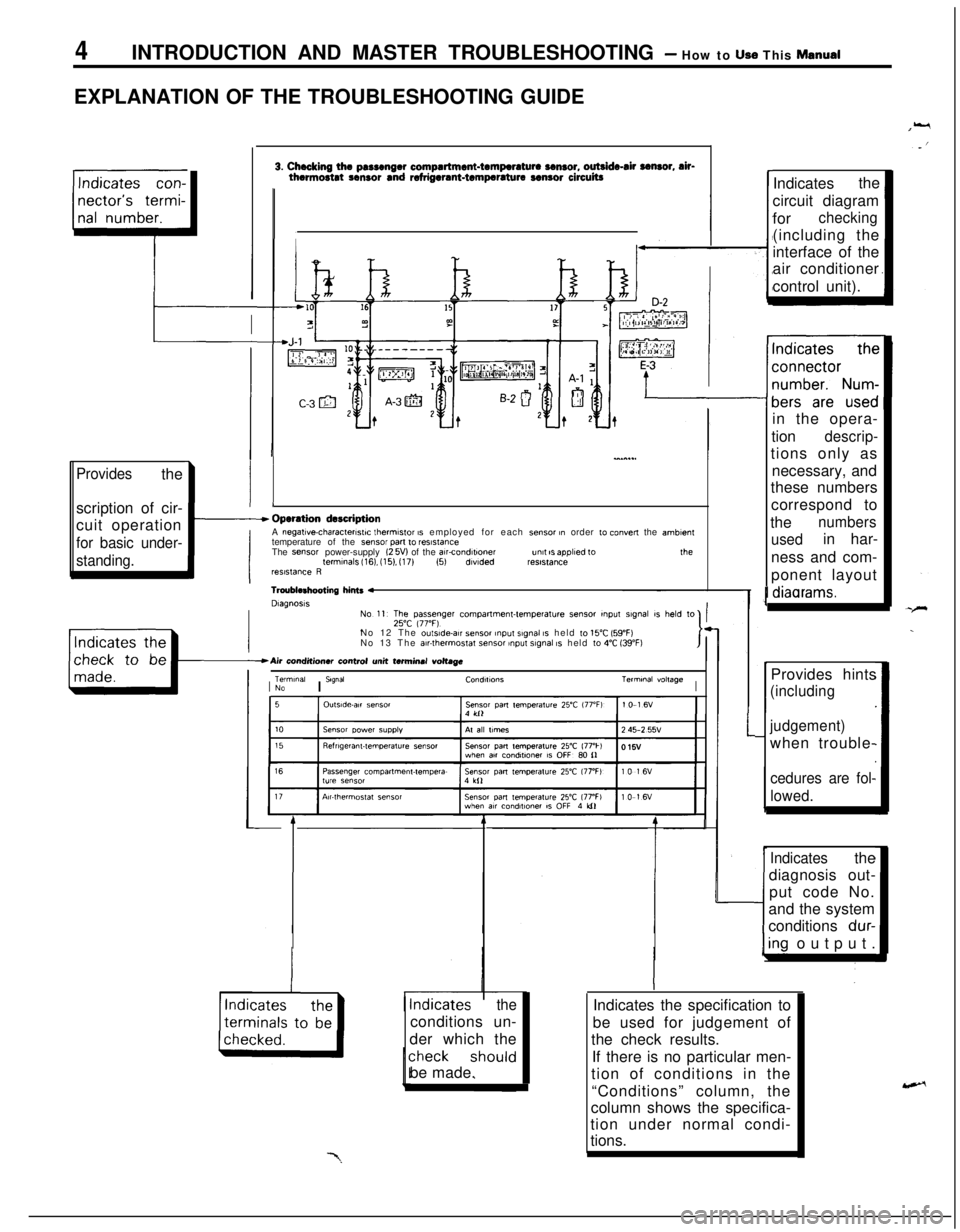
3. Checking the passenger compartment-temperature sensor, outside-air sensor, air-thermostat sensor and refrigerant-temperature sensor circuitsrIndicatesthe
circuit diagram
for
checking(including the
interface of the
air conditioner
control unit).
II*
in the opera-
tion
descrip-tions only as
necessary, and
these numbers
correspond to
the
numbers
usedin har-
ness and com-
ponent layout
l 1
I--
Operation descriptionA negative-characterlstlc thermstor 1s employed for each sensor in order 10 convey the amblenttemperature of the sensor pan ,o resistanceThe sensor power-supply I2 5V) of the awcondltww““I,ISappliedtothelermlnals116).(15).(17)(5)dlvldedres~~,ancereSlSta”ceR
Providesthe
scription of cir-
cuit operation
for basic under-
standing.
I
diaarams.Tmublrhooting 4DlagnoslsNo 12 The
ou,s,de-a,, sensor ,nput slgnal IS held to 15°C 159°F)No 13 The air-thermostat tensor ~np”t slgnal IS held 10 4°C 139°F)Provides hints
(including
judgement)when trouble-
cedures are fol-
lowed.
ITerminalI S’g”a’CO”dl,,O”*Terminal voltageNO
I
1
Indicatesthe
diagnosis out-
put code No.
and the system
conditions
dur-
kng output.
theconditions un-
der which the
be made.Indicates the specification to
be used for judgement of
the check results.
If there is no particular men-
tion of conditions in the
“Conditions” column, the
column shows the specifica-
tion under normal condi-
tions.
Page 20 of 1216
20INTRODUCTION AND MASTER TROUBLESHOOTING - Towing and Hoisting
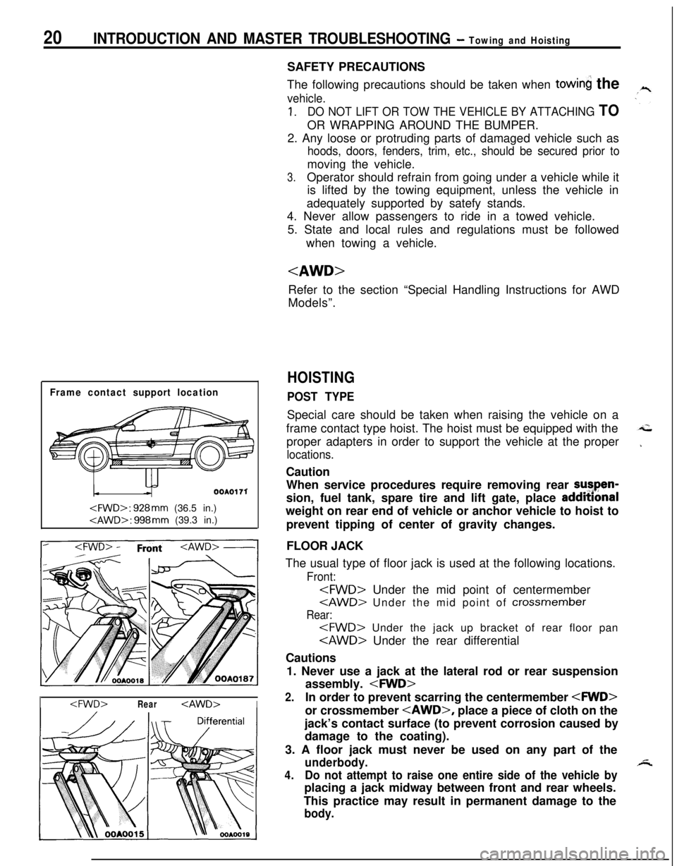
Frame contact support location
OOAOI 71
I
The following precautions should be taken when
towin the
vehicle.
1.DO NOT LIFT OR TOW THE VEHICLE BY ATTACHING TOOR WRAPPING AROUND THE BUMPER.
2. Any loose or protruding parts of damaged vehicle such as
hoods, doors, fenders, trim, etc., should be secured prior tomoving the vehicle.
3.Operator should refrain from going under a vehicle while it
is lifted by the towing equipment, unless the vehicle in
adequately supported by satefy stands.
4. Never allow passengers to ride in a towed vehicle.
5. State and local rules and regulations must be followed
when towing a vehicle.
Refer to the section “Special Handling Instructions for AWD
Models”.
HOISTING
POST TYPESpecial care should be taken when raising the vehicle on a
frame contact type hoist. The hoist must be equipped with the
proper adapters in order to support the vehicle at the proper
locations.Caution
When service procedures require removing rear sutpen-
sion, fuel tank, spare tire and lift gate, place addmonal
weight on rear end of vehicle or anchor vehicle to hoist to
prevent tipping of center of gravity changes.
FLOOR JACK
The usual type of floor jack is used at the following locations.
Front:
Rear:
Cautions
1. Never use a jack at the lateral rod or rear suspension
assembly.
2.In order to prevent scarring the centermember
jack’s contact surface (to prevent corrosion caused by
damage to the coating).
3. A floor jack must never be used on any part of the
underbody.
4.Do not attempt to raise one entire side of the vehicle byplacing a jack midway between front and rear wheels.
This practice may result in permanent damage to the
body.
Page 36 of 1216
o-2LUBRICATION AND MAINTENANCE - General Information
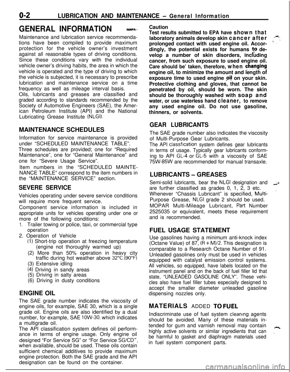
GENERAL INFORMATIONNGQPA--Maintenance and lubrication service recommenda-
tions have been compiled to provide maximum
protection for the vehicle owner’s investment
against all reasonable types of driving conditions.
Since these conditions vary with the individual
vehicle owner’s driving habits, the area in which the
vehicle is operated and the type of driving to which
the vehicle is subjected, it is necessary to prescribe
lubrication and maintenance service on a time
frequency as well as mileage interval basis.
Oils, lubricants and greases are classified and
graded according to standards recommended by theSociety of Automotive Engineers (SAE), the Amer-
ican Petroleum Institute (API) and the National
Lubricating Grease Institute
(NLGI).MAINTENANCE SCHEDULES
Information for service maintenance is provided
under “SCHEDULED MAINTENANCE TABLE”.
Three schedules are provided; one for “Required
Maintenance”, one for “General Maintenance” and
one for “Severe Usage Service”.
Item numbers in the “SCHEDULED MAINTE-
NANCE TABLE” correspond to the item numbers in
the “MAINTENANCE SERVICE” section.
SEVERE SERVICEVehicles operating under severe service conditions
will require more frequent service.
Component service information is included in
appropriate units for vehicles operating under one ormore of the following conditions:
1.Trailer towing or police, taxi, or commercial type
operation2. Operation of Vehicle
(1) Short-trip operation at freezing temperature
(engine not thoroughly warmed up)
(2) More than 50% operation in heavy city
traffic during hot weather above
32°C (90°F)(3) Extensive idling
(4) Driving in sandy areas
(5) Driving in salty areas
(6) Driving in dusty conditions
ENGINE OIL
The SAE grade number indicates the viscosity of
engine oils, for example, SAE 30, which is a single
grade oil. Engine oils are also identified by a dual
number, for example, SAE
lOW-30, which indicates
a multigrade oil.
The API classification system defines oil perform-
ance in terms of engine usage. Only engine oil
designed “For Service SG” or “For Service
SGKD”,when available, should be used. These oils contain
sufficient chemical additives to provide maximum
engine protection. Both the SAE grade and the API
designation can be found on the container.Caution
Test results submitted to EPA have shown thatlaboratory animals develop skin cancer after
prolonged contact with used engine oil. Accor-
dingly, the potential exists for humans
to de-
velop a number of skin disorders, including
cancer, from such exposure to used engine oil.
Care should be’ taken, therefore, when changingengine oil, to minimize the amount and length of
exposure time to used engine
pi! on your skin.
Protective clothing and gloves, that cannot be
penetrated by oil, should be worn. The skin
should be thoroughly washed with soap and
water, or use waterless hand cleaner, to removeany used engine oil. Do not use gasoline,
thinners, or solvents.
GEAR LUBRICANTSThe SAE grade number also indicates the viscosity
of Multi-Purpose Gear Lubricants.
The API classfication system defines gear lubricants
in terms of usage. Typically gear lubricants conform-ing to API
GL-4 or GL-5 with a viscosity of SAE
75W-85W are recommended for manual transaxle.
LUBRICANTS
- GREASES
Semi-solid lubricants, bear the NLGI designation andare further classified as grades 0, 1, 2, 3 etc.
Whenever “Chassis Lubricant” is specified, Multi-
Purpose Grease,
NLGI grade 2 should be used.
MOPAR Multi-Mileage Lubricant, P&t Number
2525035 or equivalent, meets these requirement
and is recommended.
FUEL USAGE STATEMENT
Use gasolines having a minimum anti-knock index
(Octane Value) of 87,
(R + M)/2. This designation is
comparable to a Research Octane Number of 91.
Unleaded gasolines only must be used in vehicles
equipped with catalyst emission control systems.
All vehicles, so equipped, have labels located on the
instrument panel and on the back of fuel filler lid that
state, “UNLEADED GASOLINE ONLY”. These vehi-
cles also have fuel filler tubes especially designed toaccept the smaller diameter unleaded gasoline
dispensing nozzles only.
MATERIALS ADDED
TO FUELIndiscriminate use of fuel system cleanng agents
should be avoided. Many of these materials in-
tended for gum and varnish removal may contain
highly active solvents or similar ingredients that can
be harmful to gasket and diaphragm materials usedin fuel system component parts.
Page 49 of 1216
FRONTSUSPENSION
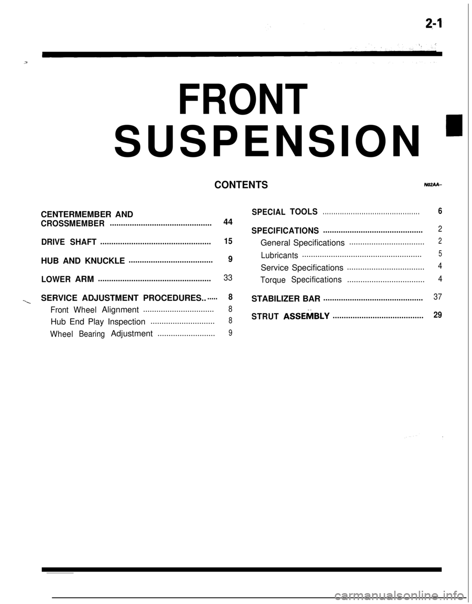
’
CONTENTSNOZAA-CENTERMEMBER AND
CROSSMEMBER..............................................44
DRIVESHAFT..................................................15HUB AND KNUCKLE
......................................9
LOWERARM
...................................................33
~SERVICE ADJUSTMENT PROCEDURES.......8
FrontWheelAlignment................................8Hub End Play Inspection
.............................8
WheelBearingAdjustment..........................9
SPECIALTOOLS. . . . . . . . . . . . . . . . . . . . . . . . . . . . . . . . . . . . . . . . . . . . .6
SPECIFICATIONS.............................................2General Specifications
..................................2
Lubricants......................................................5Service Specifications
...................................4
TorqueSpecifications...................................4STABILIZER BAR
.............................................37
STRUTASSEMBLY.........................................29
Page 53 of 1216
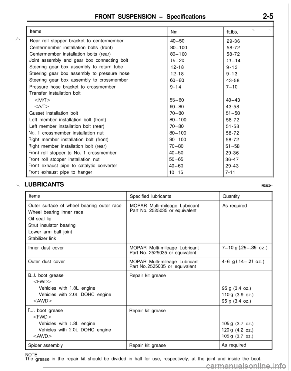
FRONT SUSPENSION - Specifications2-5Items
Rear roll stopper bracket to centermember
Centermember installation bolts (front)
Centermember installation bolts (rear)
Joint assembly and gear box connecting bolt
Steering gear box assembly to return tube
Steering gear box assembly to pressure hose
Steering gear box assembly to crossmember
Pressure hose bracket to crossmember
Transfer installation bolt
Nmftlbs. I’, ‘,
40-5029-36
80-10058-72
80-I 0058-72
15-20II-1412-18
9-13
12-189-13
60-8043-58
9-14
7-10
55-6040-43
Gusset installation bolt
70-8051-58Left member installation bolt (front)
80-10058-72
Left member installation bolt (rear)
70-8051-58
Vo. 1 crossmember installation nut80-10058-72qight member installation bolt (front)
80-10058-72?ight member installation bolt (rear)
70-8051-58
+ont roll stopper to No. 1 crossmember40-5029-36
?ont roll stopper installation nut50-6536-47
Iront exhaust pipe to catalytic converter40-6029-43
‘rant exhaust pipe to hangerIO-157-11
‘-. LUBRICANTSNO2CD--
ItemsSpecified lubricantsQuantity
Outer surface of wheel bearing outer race
MOPAR Multi-mileage LubricantAs required
Wheel bearing inner racePart No. 2525035 or equivalent
Oil seal lip
Strut insulator bearing
Lower arm ball joint
Stabilizer link
Inner dust coverMOPAR Multi-mileage Lubricant
Part No. 2525035 or equivalent
7-10 g (.25-.35 oz.)
Outer dust cover
MOPAR Multi-mileage Lubricant
Part
No.2525035 or equivalent4-6
g (.14-.21 oz.)
B.J. boot grease
Repair kit grease
1.8L engine
95 g (3.4 oz.)
Vehicles with
2.0L DOHC engine110 g (3.9 oz.)
T.J. boot grease
Repair kit grease
1.8L engine105 g (3.7 oz.)
Vehicles with
2.0L DOHC engine120 g (4.2 oz.)
Spider assemblyRepair kit greaseAs required
NOTEThe grease in the repair kit should be divided in half for use, respectively, at the joint and inside the boot.
Page 68 of 1216
FRONT SUSPENSION - Drive Shaft
IllA0127
llE560
Grease
llE563
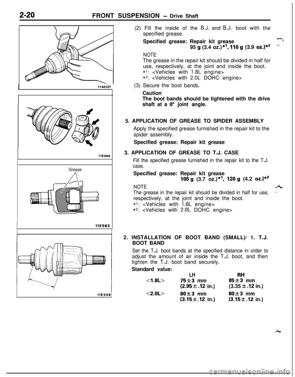
llE559(2) Fill the inside of the
B.J. and B.J., boot with the
specified grease.
Specified grease: Repair kit grease
Wil95
g (3.4 oz.)*I, 110 g (3.9 oz.)**-
NOTEThe grease in the repair kit should be divided in half for
use, respectively, at the joint and inside the boot.
*I:
*2:
(3) Secure the boot bands.
Caution
The boot bands should be tightened with the drive
shaft at a
0” joint angle.
5. APPLICATION OF GREASE TO SPIDER ASSEMBLY
Apply the specified grease furnished in the repair kit to the
spider assembly.
Specified grease: Repair kit grease
3. APPLICATION OF GREASE TO T.J. CASE
Fill the specified grease furnished in the repair kit to the T.J.
case.Specified grease: Repair kit grease
105 g (3.7 oz.)*‘I,120 g (4.2 oz.)**
NOTEA
The grease in the repair kit should be divided in half for use,-respectively, at the joint and inside the boot.
*I:
*2:
2. INSTALLATION OF BOOT BAND (SMALL)/ 1. T.J.
BOOT BAND
Set the T.J. boot bands at the specified distance in order toadjust the amount of air inside the T.J. boot, and then
tighten the T.J. boot band securely.
Standard value:
LHRH
(2.95f .I2 in.)(3.35 f .I2 in.)
<2.0L>80f3 mmSO+3 mm
(3.15f.12 in.)(3.15+ .I2 in.)
Page 74 of 1216
2-26FRONT SUSPENSION - Drive Shaft
llE560
INSPECTIONN02QGEB
0
0
0
0Check the dust cover for damage or deterioration.Check the drive shaft for damage, bending or corrosion.
Check the inner shaft for damage, bending or corrosion.
-Check the drive shaft spline part for wear or damage.
=-Check the inner shaft spline for wear or damage.
Check for entry of water and/or foreign material into
B-J..Check the spider assembly for roller rotation, wear or
corrosion.Check the groove inside T.J. case for wear of corrosion.
Check the boots for deterioration, damage or cracking.
Check the center bearing for seizure, discoloration or
roughness of rolling surface.
SERVICE POINTS OF REASSEMBLY
NOZQHEEa
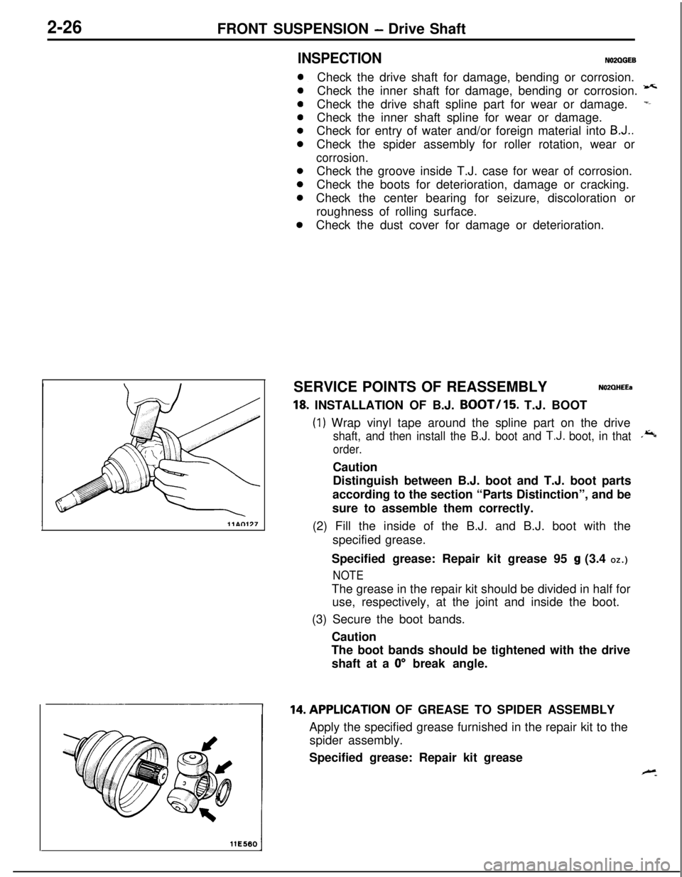
18, INSTALLATION OF B.J. BOOT/15. T.J. BOOT
(1) Wrap vinyl tape around the spline part on the drive
shaft, and then install the B.J. boot and T.J. boot, in that.*
order.Caution
Distinguish between B.J. boot and T.J. boot parts
according to the section “Parts Distinction”, and be
sure to assemble them correctly.
(2) Fill the inside of the B.J. and B.J. boot with the
specified grease.
Specified grease: Repair kit grease 95
g (3.4 OZ.)
NOTEThe grease in the repair kit should be divided in half for
use, respectively, at the joint and inside the boot.
(3) Secure the boot bands.
Caution
The boot bands should be tightened with the drive
shaft at a
0” break angle.14.APPLlCATlON OF GREASE TO SPIDER ASSEMBLY
Apply the specified grease furnished in the repair kit to the
spider assembly.
Specified grease: Repair kit grease
Page 76 of 1216
2-28FRONT SUSPENSION - Drive Shaft
Inner shaft
llA0083
1T.J. case.,
MB9909383%QilD998801
r
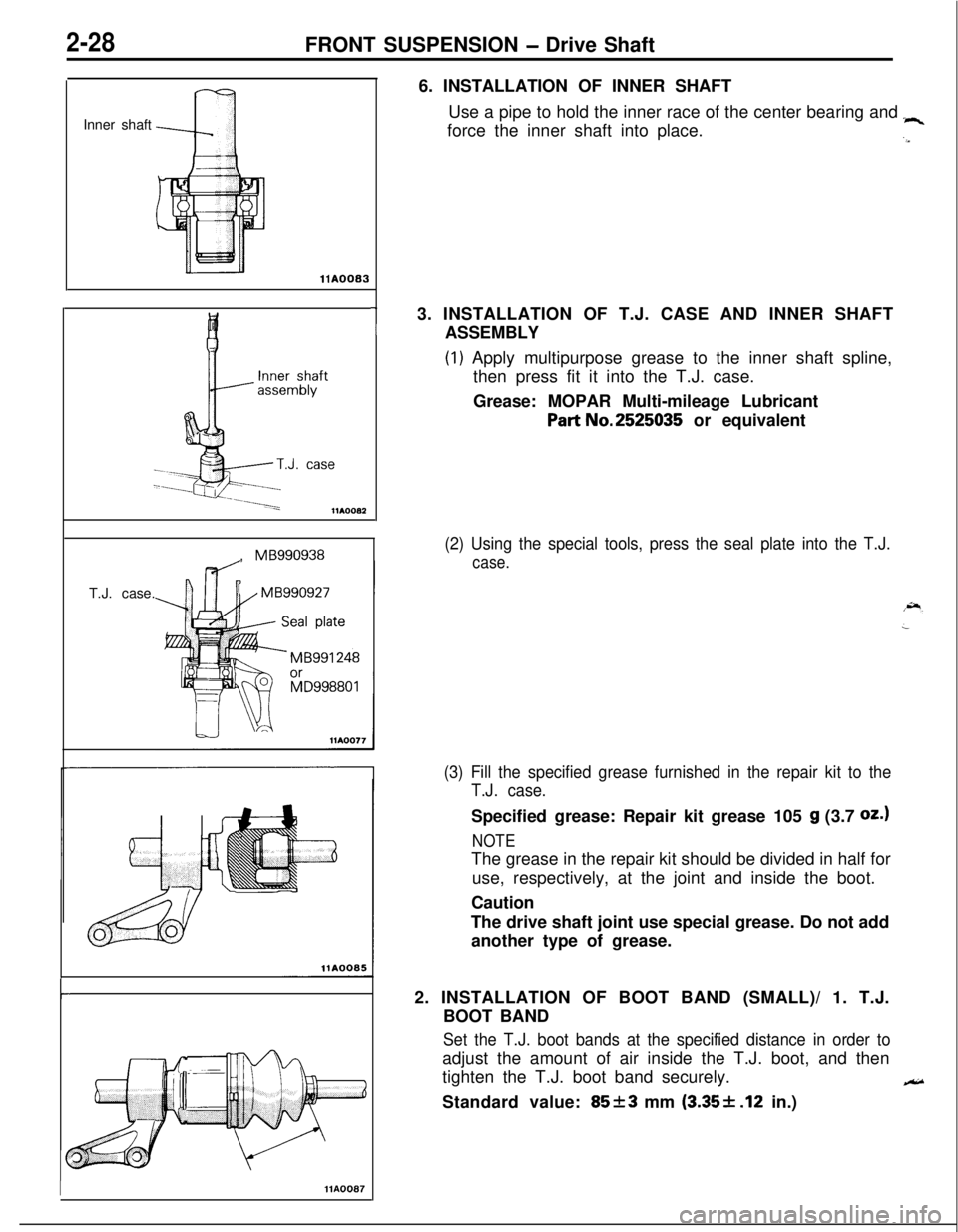
IHA00876. INSTALLATION OF INNER SHAFT
Use a pipe to hold the inner race of the center bearing and
“4force the inner shaft into place.
.a3. INSTALLATION OF T.J. CASE AND INNER SHAFT
ASSEMBLY
(1) Apply multipurpose grease to the inner shaft spline,
then press fit it into the T.J. case.
Grease: MOPAR Multi-mileage Lubricant
Part No.2525035 or equivalent
(2) Using the special tools, press the seal plate into the T.J.
case.
(3) Fill the specified grease furnished in the repair kit to the
T.J. case.Specified grease: Repair kit grease 105
g (3.7 oz.1
NOTEThe grease in the repair kit should be divided in half for
use, respectively, at the joint and inside the boot.
Caution
The drive shaft joint use special grease. Do not add
another type of grease.
2. INSTALLATION OF BOOT BAND (SMALL)/ 1. T.J.
BOOT BAND
Set the T.J. boot bands at the specified distance in order toadjust the amount of air inside the T.J. boot, and then
tighten the T.J. boot band securely.
eStandard value:
85f3 mm (3.35+ .12 in.)