Water turbo MITSUBISHI ECLIPSE 1991 Service Manual
[x] Cancel search | Manufacturer: MITSUBISHI, Model Year: 1991, Model line: ECLIPSE, Model: MITSUBISHI ECLIPSE 1991Pages: 1216, PDF Size: 67.42 MB
Page 37 of 1216
LUBRICATION AND MAINTENANCE - Scheduled MaintenanCe Table. &3
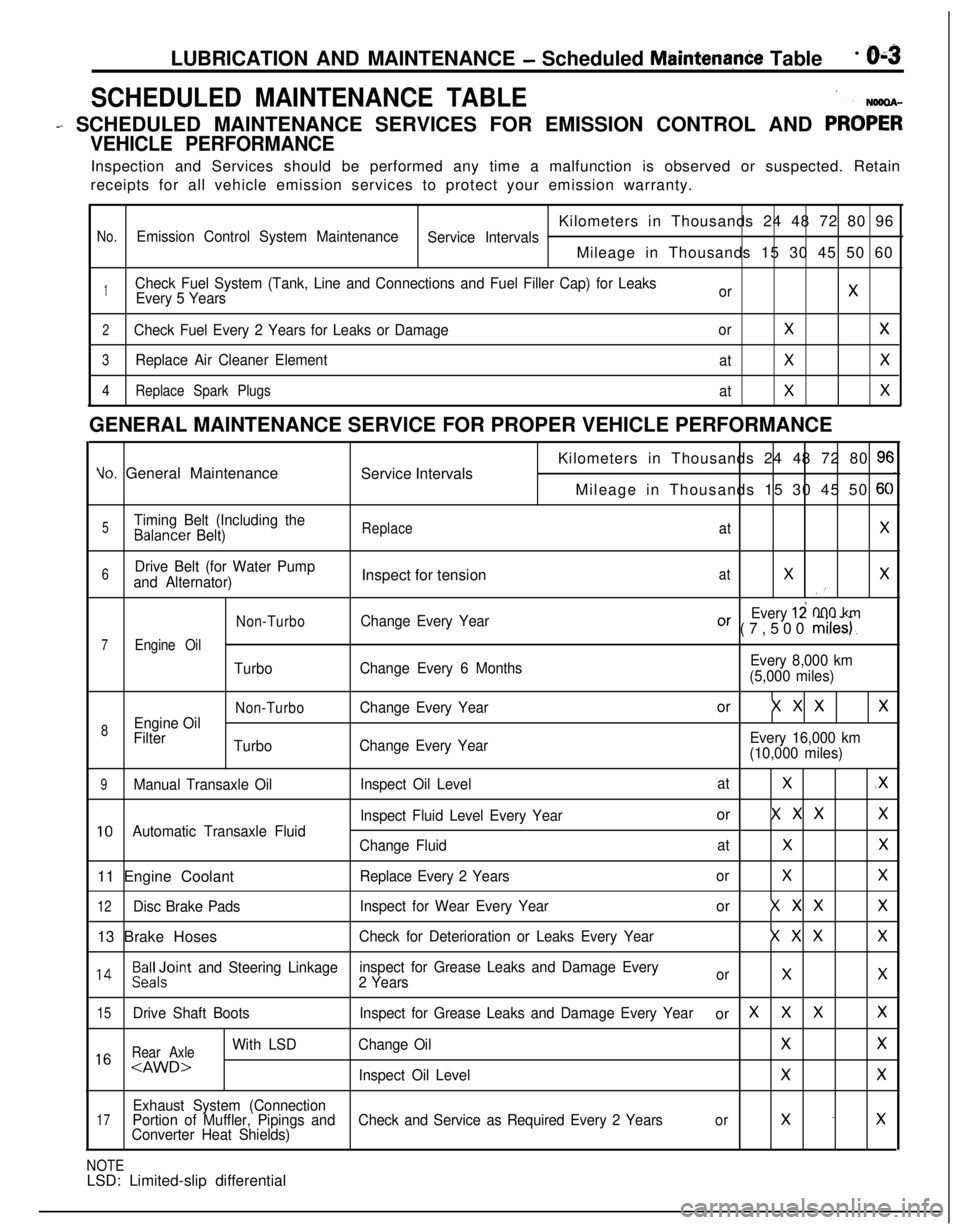
SCHEDULED MAINTENANCE TABLE1
- SCHEDULED MAINTENANCE SERVICES FOR EMISSION CONTROL AND PRO;;
VEHICLE PERFORMANCEInspection and Services should be performed any time a malfunction is observed or suspected. Retain
receipts for all vehicle emission services to protect your emission warranty.
Kilometers in Thousands 24 48 72 80 96
No.Emission Control System Maintenance
Service IntervalsMileage in Thousands 15 30 45 50 60
1Check Fuel System (Tank, Line and Connections and Fuel Filler Cap) for Leaks
Every 5 YearsorX
2Check Fuel Every 2 Years for Leaks or DamageorXX
3Replace Air Cleaner Element
atXX
4Replace Spark Plugs
atXXGENERAL MAINTENANCE SERVICE FOR PROPER VEHICLE PERFORMANCE
Yo. General Maintenance
Service IntervalsKilometers in Thousands 24 48 72 80 9cMileage in Thousands 15 30 45 50
6C
5Timing Belt (Including theBalancer Belt)ReplaceatX
6Drive Belt (for Water Pump
and Alternator)Inspect for tensionatXX.’
Non-TurboChange Every YearEvery 12 000 kmOr (7,500 miles).
7Engine Oil
TurboChange Every 6 MonthsEvery 8,000 km
(5,000 miles)
Non-TurboChange Every Yearor X X XX
8Engine Oil
Filter
TurboChange Every YearEvery 16,000 km
(10,000 miles)
9Manual Transaxle OilInspect Oil LevelatX.X
Inspect Fluid Level Every Yearor X X XX
10Automatic Transaxle Fluid
Change FluidatXX11 Engine Coolant
Replace Every 2 YearsorXX
12Disc Brake PadsInspect for Wear Every Yearor X X XX13 Brake Hoses
Check for Deterioration or Leaks Every YearX X XX
l 4Beiloint and Steering Linkageinspect for Grease Leaks and Damage Every
2 YearsorXX
15Drive Shaft BootsInspect for Grease Leaks and Damage Every Yearor XXXX
Rear Axle
With LSDChange OilXX1 6
Exhaust System (Connection17Portion of Muffler, Pipings andCheck and Service as Required Every 2 Yearsorx -xConverter Heat Shields)
NOTELSD: Limited-slip differential
Page 42 of 1216
O-8LUBRICATION AND MAINTENANCE - Maintenance Service
0-L
I-TOlLO182
-
, ,6COOO9
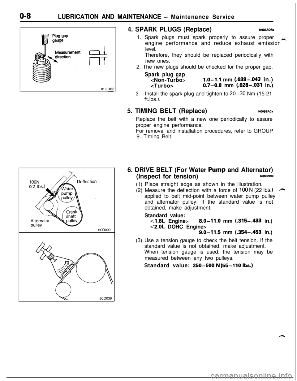
u6COO394. SPARK PLUGS (Replace)
NOOSAOFa1. Spark plugs must spark properly to assure proper
~engine performance and reduce exhaust emission
level.Therefore, they should be replaced periodically with
new ones.
2. The new plugs should be checked for the proper gap.
Spark plug gap
1.0-1.1 mm (.039-.043 in.)
0.7-0.8 mm (.028-.031 in.)
3.Install the spark plug and tighten to 20-30 Nm (15-21
ft.lbs.).5. TIMING BELT (Replace)
NOOSBACaReplace the belt with a new one periodically to assure
proper engine performance.
For removal and installation procedures, refer to GROUP
g-Timing Belt.
6. DRIVE BELT (For Water
Pump and Alternator)
(Inspect for tension)
NOOSSBN(1) Place straight edge as shown in the illustration.
(2) Measure the deflection with a force of
100 N (22 Ibs.)rzapplied to belt mid-point between water pump pulley
-and alternator pulley. If the standard value is not
obtained, make adjustment.
Standard value:
<1.8L Engine>8.0-11.0 mm (.315-A33 in.)
<2.0L DOHC Engine>
9.0-11.5 mm (.354-.453 in.)
(3) Use a tension gauge to check the belt tension. If the
standard value is not obtained, make adjustment.
When tension gauge is used, the tension may be
measured between any two pulleys.
Standard value:
250-500 N (55-110 Ibs.)
Page 249 of 1216
7-l
COOLING
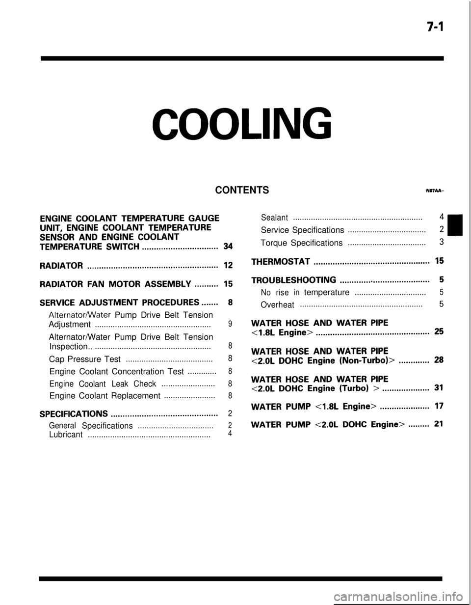
CONTENTS
ENGINE COOLANT TEMPERATURE GAUGEUNIT,
ENGINE COOLANT TEMPERATURE
SENSOR AND ENGINE COOLANT
TEMPERATURE SWITCH................................34
RADIATOR.......................................................12
RADIATORFANMOTOR ASSEMBLY..........15
SERVICE ADJUSTMENT PROCEDURES.......8
Alternatormater Pump Drive Belt Tension
Adjustment
....................................................9Alternator/Water Pump Drive Belt Tension
Inspection..
....................................................8Cap Pressure Test
.......................................8Engine Coolant Concentration Test
.............8
EngineCoolantLeakCheck........................8Engine Coolant Replacement
.......................8
SPECIFICATIONS.............................................2
GeneralSpecifications..................................2
Lubricant.......................................................4
Sealant..........................................................4Service Specifications
...................................2Torque Specifications
...................................3THERMOSTAT
.................................................15
TROUBLESHOOTING......................................5
Noriseintemperature................................5
Overheat.......................................................5
WATER HOSE AND WATER PIPE
<1.8L Engine>................................................25
WATER HOSE AND WATER PIPE
<2.0LDOHCEngine(Non-Turbo)>.............28
WATER HOSE AND WATER PIPE
<2.0LDOHCEngine(Turbo)>....................31
WATERPUMP<1.8LEngine>.....................17
WATER PUMP <2.0L DOHC Engine>.........21
Page 251 of 1216
COOLING - Specifications7-3
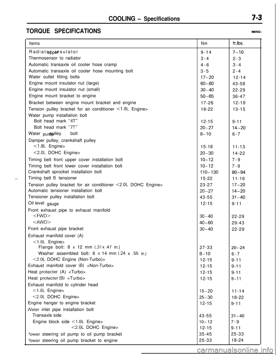
TORQUE SPECIFICATIONSN07CG.
ItemsRadiator insulator
upperThermosensor to radiator
Automatic transaxle oil cooler hose cramp
Automatic transaxle oil cooler hose mounting bolt
Water outlet fitting bolts
Engine mount insulator nut (large)
Engine mount insulator nut (small)
Engine mount bracket to engine
Bracket between engine mount bracket and engine
Tension pulley bracket for air conditioner
<1.8L Engine>
Water pump installation bolt
Bolt head mark “4T”
Bolt head mark “7T”
Water pulley bolt
pumpDamper pulley, crankshaft pulley
<1.8L Engine>
<2.0L DOHC Engine>
Timing belt front upper cover installation bolt
Timing belt front lower cover installation bolt
Crankshaft sprocket installation bolt
Timing belt
B tensioner
Tension pulley bracket for air conditioner
<2.0L DOHC Engine>
Automatic tensioner installation bolt
Tensioner pulley installation bolt
Oil level
gaugeFront exhaust pipe to exhaust manifold
Exhaust manifold cover (A)
Flange bolt: 8
x 12 mm (.31 x .47 in.)
Washer assembled bolt: 6
x 14 mm (.24x.55in.)
<2.0L DOHC Engine (Non-Turbo)>
Exhaust manifold cover
(8)
Heat protecter (A)
Heat protecter
(B)
Exhaust manifold to cylinder head<1.8L Engine>
<2.0L DOHC Engine>
Engine hanger to engine bracket
JVater inlet pipe installation bolt
Transaxle side
Engine block side
<1.8L Engine>
<2.0L DOHC Engine>
'ower steering oil pump to oil pump bracket
‘ower steering oil pump bracket to engine
Nmft.lbs.
9-14
7-103-4
2-3
4-63-4
3-52-4
17-2012-14
60-8043-58
30-4022-29
50-6536-47
17-2612-19
18-2213-15
12-15
9-11
20-2714-20
8-106-7
15-18
11-13
20-3014-22
IO-127-9
10-127-9
110-13080-9415-22
11-16
23-27
17-20
20-2714-2043-55
31-4012-15
9-11
30-4022-29
40-6029-43
30-4022-29
27-33
20-24
8-106-7
12-15
9-11
12-15
9-11
12-15
9-11
12-15
9-l 1
15-2011-14
25-3018-22
12-15
9-11
43-55
31-40
IO-127-9
12-15
9-11
35-4525-33
25-3318-24
Page 252 of 1216
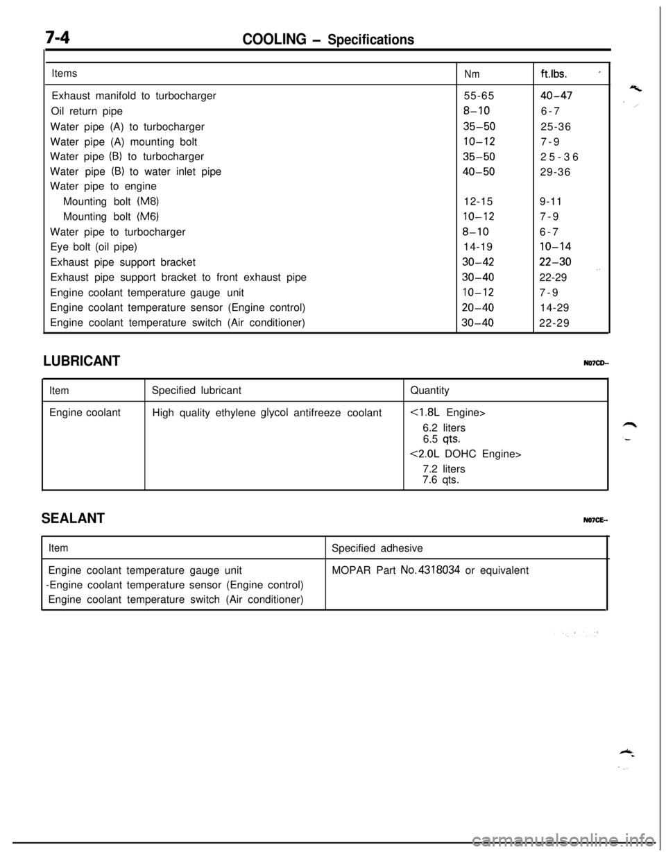
7-4COOLING - Specifications
ItemsExhaust manifold to turbocharger
Oil return pipe
Water pipe (A) to turbocharger
Water pipe (A) mounting bolt
Water pipe
(B) to turbocharger
Water pipe
(B) to water inlet pipe
Water pipe to engine
Mounting bolt
(M8)Mounting bolt
(M6)Water pipe to turbocharger
Eye bolt (oil pipe)
Exhaust pipe support bracket
Exhaust pipe support bracket to front exhaust pipe
Engine coolant temperature gaugeunit
Engine coolant temperature sensor (Engine control)
Engine coolant temperature switch (Air conditioner)
Nmft.lbs. _155-65
40-47
8-106-7
35-5025-36
10-127-9
35-5025-36
40-5029-36
12-159-11
10-127-9
8-106-7
14-19
10-14
30-4222-30
30-4022-29 .’
10-127-9
20-4014-29
30-4022-29
LUBRICANT
ItemEngine coolantSpecified lubricant
High quality ethylene
glycol antifreeze coolantQuantity
6.2 liters
6.5
qts.
<2.0L DOHC Engine>
7.2 liters
7.6 qts.
SEALANTNO7CE-.
ItemEngine coolant temperature gauge unit
-Engine coolant temperature sensor (Engine control)
Engine coolant temperature switch (Air conditioner)Specified adhesive
MOPAR Part No.4318034 or equivalent
Page 260 of 1216
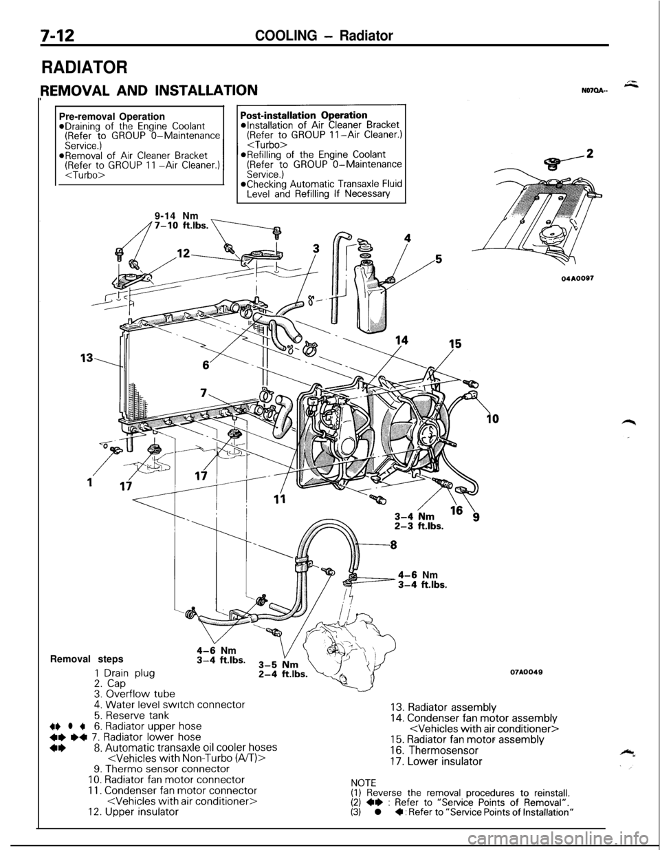
7-12COOLING - Radiator
RADIATORPre-removal Operation
@Draining of the Engine Coolant(Refer to GROUP O-Maintenance(Refer to GROUP II-Air Cleaner.)
Service.)
I I
9-14 Nm
_
4-6 Nm3-4 ft.lbs.Removal steps
1 Drain plug2. Cap3. Overflow tube.
4-9 Nm3-4 ft.lbs.
4. Water level switch connector
5. Reserve tank~~ l +6. Radiator upper hose
+e e+ 7. Radiator lower hose
*I)8. Automatic transaxle oil cooler hoses
11. Condenser fan motor connector
04AOOS7
07A0049
13. Radiator assembly14. Condenser fan motor assembly
16. Thermosensor
17. Lower insulator
NOTE(1) Reverse the removal procedures to reinstall.(2) +e : Refer to “Service Points of Removal”.(3) l + : Refer to “Service Points of Installation”
Page 276 of 1216
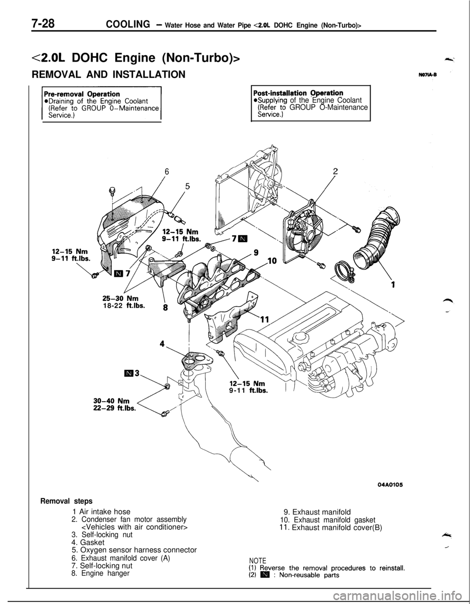
7-28COOLING- Water Hose and Water Pipe <2.0L DOHC Engine (Non-Turbo)>
<2.0L DOHC Engine (Non-Turbo)>
REMOVAL AND INSTALLATION
Post-installgtion Pperation@Supplying of the Engine Coolant(FF$efeet; GROUP O-Maintenance
6
/5
/l--5ia
225-30 Nm
18-22
ft.lbs.
12-1s Nrn9-11 ft.lbs.
Removal steps1 Air intake hose
2. Condenser fan motor assembly
3. Self-locking nut4. Gasket
5. Oxygen sensor harness connector
6. Exhaust manifold cover (A)7. Self-locking nut
8. Engine hanger
04A01059. Exhaust manifold
10. Exhaust manifold gasket11. Exhaust manifold cover(B)
NOTE(1) Reverse the removal procedures to reinstall.(21 m : Non-reusable parts
Page 277 of 1216
,-
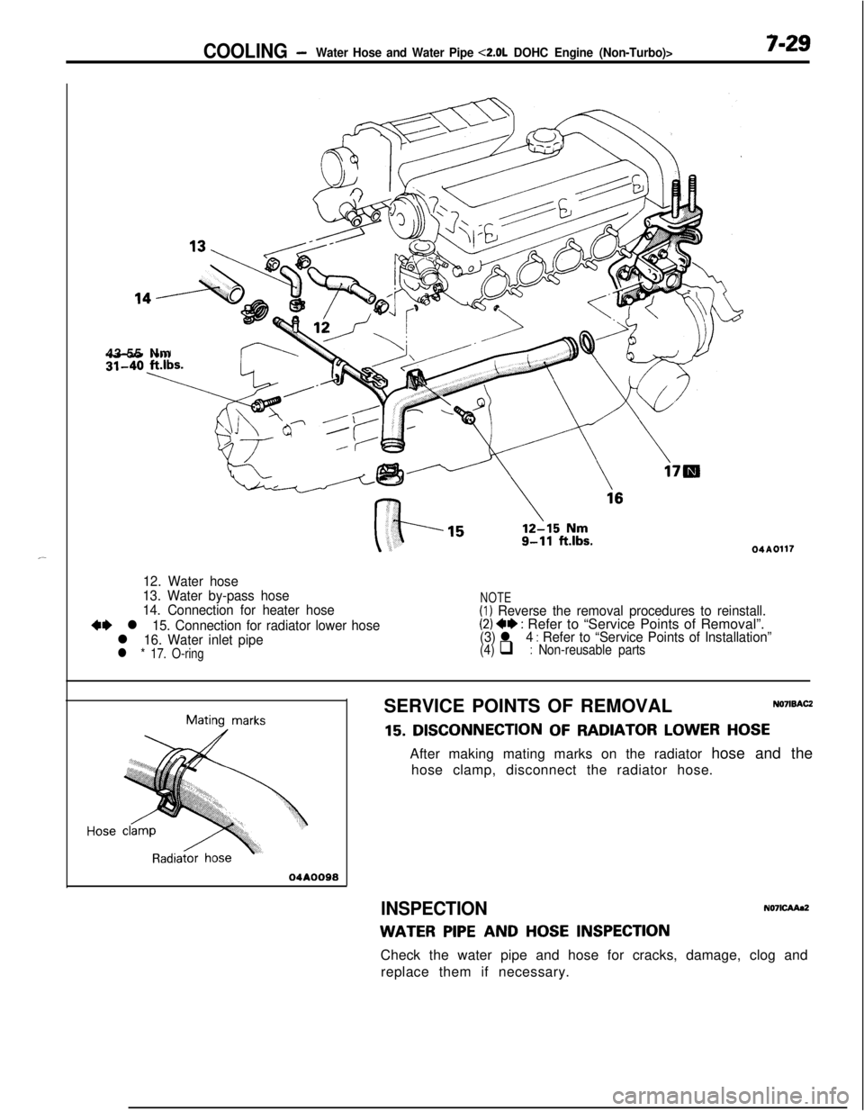
COOLING -Water Hose and Water Pipe <2.0L DOHC Engine (Non-Turbo)>7-2943-55 Nm
04A0117
12. Water hose
13. Water by-pass hose
14. Connection for heater hose
+I) l 15. Connection for radiator lower hose
l 16. Water inlet pipel * 17. O-ring
NOTE(1) Reverse the removal procedures to reinstall.(2) 4* : Refer to “Service Points of Removal”.(3) l 4 : Refer to “Service Points of Installation”(4) q : Non-reusable parts
Mating marks
04AOO98SERVICE POINTS OF REMOVAL
NO’IISACZ
15. DISCONNECTION OF RADIATOR LOWER HOSEAfter making mating marks on the radiator hose and the
hose clamp, disconnect the radiator hose.
INSPECTIONN071CAAa2
WATER PIPE AND HOSE INSPECTIONCheck the water pipe and hose for cracks, damage, clog and
replace them if necessary.
Page 278 of 1216
7-30COOLING - waterHose and Water Piue <2.0L DOHC Ermine (Non-Turbo)>
04ROO24
04AOO98SERVICE POINTS OF INSTALLATION
N071DAJZ
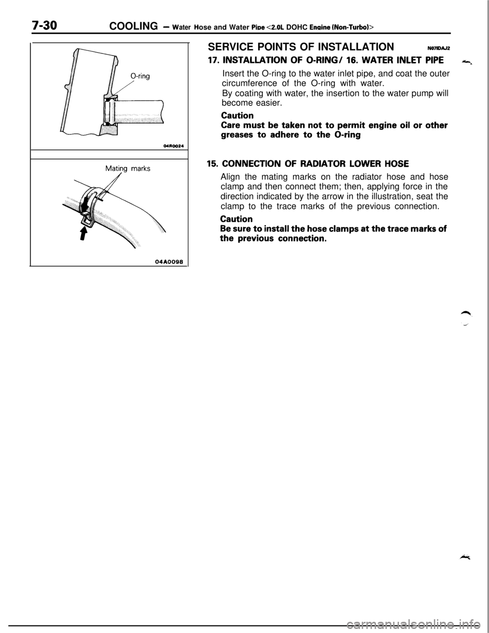
17. INSTALLATION OF O-RING/ 16. WATER INLET PIPE“4Insert the O-ring to the water inlet pipe, and coat the outer
circumference of the O-ring with water.
By coating with water, the insertion to the water pump will
become easier.Caution
Care must be taken not to permit engine oil or other
greases to adhere to the O-ring
15. CONNECTION OF RADIATOR LOWER HOSEAlign the mating marks on the radiator hose and hose
clamp and then connect them; then, applying force in the
direction indicated by the arrow in the illustration, seat the
clamp to the trace marks of the previous connection.Caution
Be sure to install the hose clamps at the trace marks ofthe
previous connection.
Page 279 of 1216
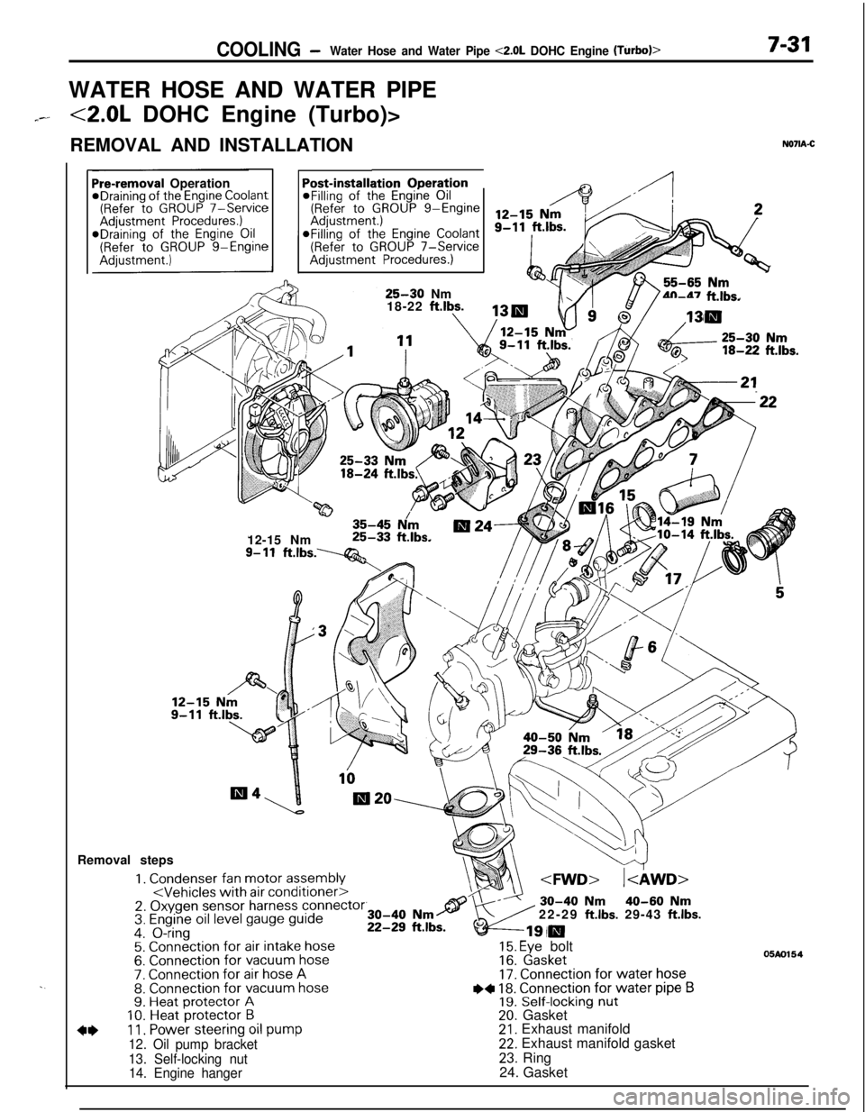
COOLING -Water Hose and Water Pipe <2.0L DOHC Engine (Turbo)>7-31WATER HOSE AND WATER PIPE
7--<2.0L DOHC Engine (Turbo)>
REMOVAL AND INSTALLATION
N071A-C
. .
ation OperationPost-installi@Filling of the Engine Oil(Refer to GROUP g-EngineaFilling of the
Engine Coolant(Refer to GROUP 7-ServiceAdjustment Procedures.)
Pre-removal OperationeDraining of the Engine Coolant(Refer to GROUP 7-ServiceAdjustment Procedures.)*Draining of the Engine Oil(Refer to GROUP g-Engine
25-30 Nm
18-22 ftlbs.4n-47 ft.lbs.
w35-45 N/m12-15 Nm25-33 ft.lbs.
9- 11ft.lbs.----Q&Removal steps
1. Condenser fan motor assembly
4*11. Power steering oil pump
12. Oil pump bracket
13. Self-locking nut
14. Engine hanger22-29
ft.lbs. 29-43 ft.lbs.
15. Eye bolt16. Gasket17. Connection for water hose
I)+ 18. Connection for water pipe B19. Self-locking nut20. Gasket21. Exhaust manifold22. Exhaust manifold gasket
23. Ring
24. Gasket
05m154