run flat MITSUBISHI ECLIPSE 1991 Service Manual
[x] Cancel search | Manufacturer: MITSUBISHI, Model Year: 1991, Model line: ECLIPSE, Model: MITSUBISHI ECLIPSE 1991Pages: 1216, PDF Size: 67.42 MB
Page 141 of 1216
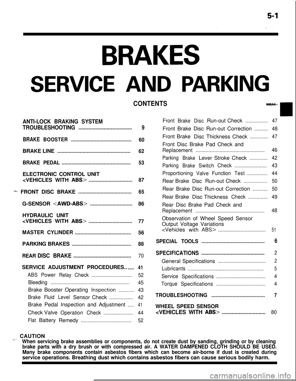
BRAKES
SERVICE AND PARKING
CONTENTS
ANTI-LOCK BRAKING SYSTEM
TROUBLESHOOTING
......................................
9
BRAKEBOOSTER...........................................
60BRAKE LINE
....................................................
62
BRAKE PEDAL.................................................
53ELECTRONIC CONTROL UNIT
- FRONT DISC BRAKE......................................
65G-SENSOR
HYDRAULIC UNIT
77
MASTERCYLINDER
........................................56
PARKING BRAKES
..........................................88
REAR
DISC BRAKE.........................................70SERVICE ADJUSTMENT PROCEDURES..
.....41
ABSPowerRelayCheck.............................52
Bleeding........................................................
45Brake Booster Operating
Inspection...........43
BrakeFluidLevelSensor Check.................
42Brake Pedal Inspection and Adjustment
.....41Check Valve
OperationCheck.....................
44
FlatBattery
Remedy....................................52
FrontBrakeDiscRun-out Check................47Front Brake Disc Run-out Correction
..........48Front Brake
Disc Thickness Check
.............47Front Disc Brake Pad Check and
Replacement.................................................46
Parking
BrakeLever Stroke Check.............42
Parking
BrakeSwitchCheck.......................43
Proportioning
ValveFunctionTest...............44Rear Brake
DiscRun-out Check.................50Rear Brake Disc Run-out Correction
...........50Rear Brake
Disc Thickness
Check..............49Rear Disc Brake Pad Check and
Replacement.................................................48Observation of Wheel Speed Sensor
Output Voltage Variations
ABS>..................................51
SPECIAL TOOLS.............................................6
SPECIFICATIONS.............................................
2General Specifications
..................................2
Lubricants
......................................................5
Service
Specifications...................................4
Torque
Specifications...................................4
TROUBLESHOOTING......................................7WHEEL SPEED SENSOR
_ CAUTION
When servicing brake assemblies or components, do not create dust by sanding, grinding or by cleaning
brake parts with a dry brush or with compressed air. A WATER DAMPENED CLOTH SHOULD BE USED.
Many brake components contain asbestos fibers which can become air-borne if dust is created duringservice operations. Breathing dust which contains asbestos fibers can cause serious bodily harm.
Page 660 of 1216
19-12STEERING - Service Adjustment Procedures
Pressure ofWater pump
pulleyOlA0059Fluid fluctuation
While engine
runningWhile enginestopped13uo139
Return hoseVinyl hose
x ,3Ao,42-
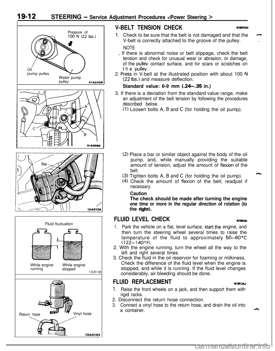
V-BELT TENSION CHECKNlSFliAl
1.Check to be sure that the belt is not damaged and that the
V-belt is correctly attached to the groove of the pulley.
NOTE, If there is abnormal noise or belt slippage, check the belt
tension and check for unusual wear or abrasion, or damage,
of the
pullev contact surface, and for scars or scratches onthe
pulley.2.
Press in V-belt at the illustrated position with about 100 N
(22 Ibs.) and measure deflection.
Standard value: 6-9 mm
1.26.35 in.)
3. If there is a deviation from the standard value range, make
an adjustment of the belt tension by following the procedures
described below.
(1) Loosen bolts A, B and C (for holding the oil pump).
(2) Place a bar or similar object against the body of the oil
pump, and, while manually providing the suitable
amount of tension, adjust the amount of
flexion of the
belt.
(3) Tighten bolts A, B and C (for holding the oil pump).
(4) Check the amount of flexion of the belt; readjust if
necessary.
CautionThe check should be made after turning the engine
one time or more in the regular direction of rotation (tothe
dght).
FLUID LEVEL CHECKNlSFIAI
1.Park the vehicle on a flat, level surface, startthe engine, andthen turn the steering wheel several times to raise the
temperature of the fluid to approximately
50-60°C
(122-140°F).2. With the engine running, turn the wheel all the way to the
left and right several times.3. Check the fluid in the oil reservoir for foaming or milkiness.
Check the difference of the fluid level when the engine is
stopped, and while it is running. If the fluid level changes
considerably, air bleeding should be done.
FLUID REPLACEMENTNlSFJAJ
1.Raise the front wheels on a jack, and then support them with
rigid racks.2. Disconnect the return hose connection.
3.Connect a vinyl hose to the return hose, and drain the oil into
a container.
Page 1039 of 1216
22-l-.
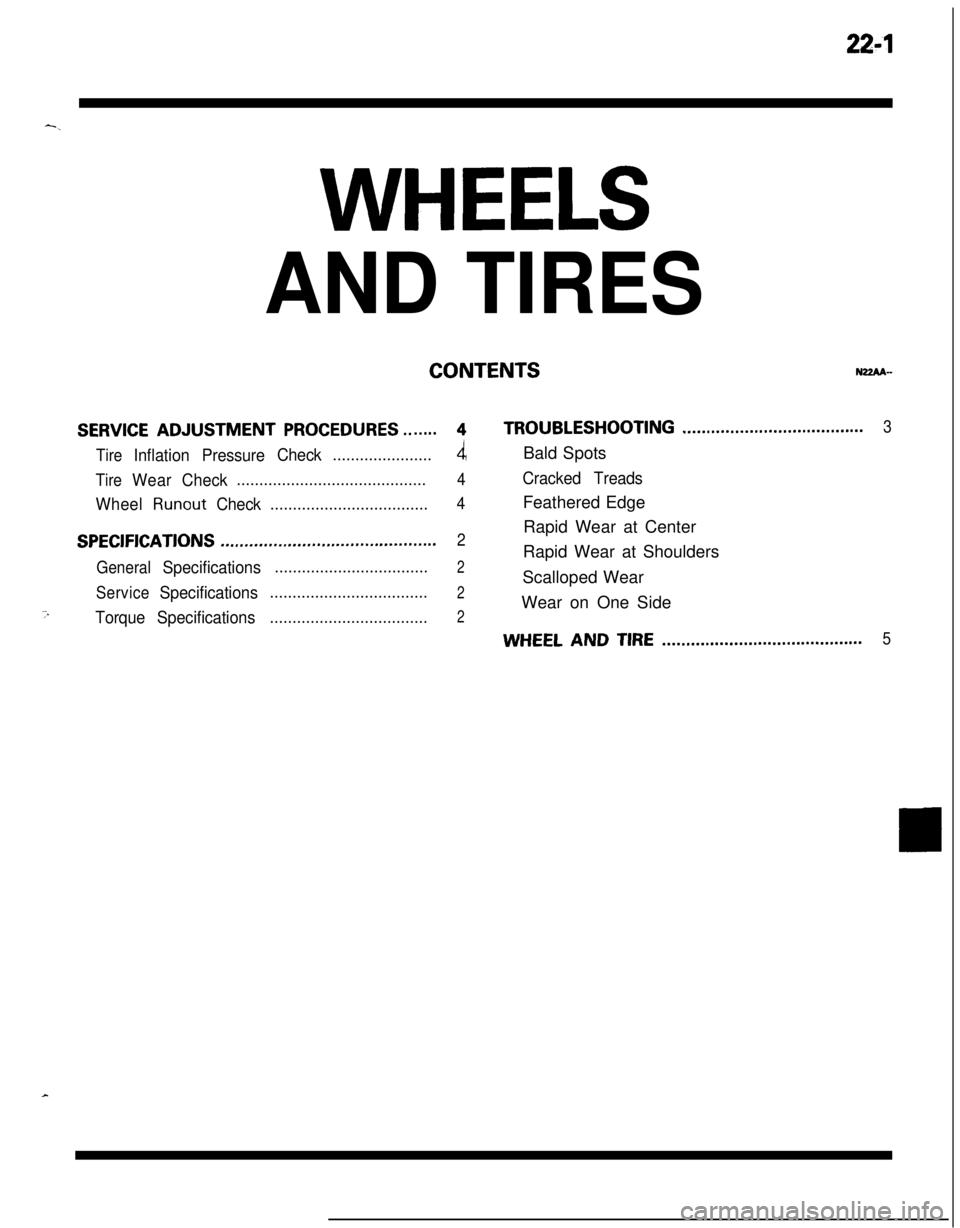
WHEELS
AND TIRES
CONTENTSNZZAA-
SERVICE ADJUSTMENT PROCEDURES.......4TROUBLESHOOTING......................................3
Tire
InflationPressureCheck......................4Bald Spots
TireWearCheck..........................................4Cracked Treads
Wheel
RunoutCheck...................................4Feathered Edge
SPECIFICATIONSRapid Wear at Center.............................................2
General
Specifications..................................2Rapid Wear at Shoulders
ServiceSpecificationsScalloped Wear...................................2Wear on One Side
7TorqueSpecifications...................................2
WHEEL AND TIRE..........................................5
Page 1040 of 1216
5 22-2WHEELS AND TIRES - Specifications
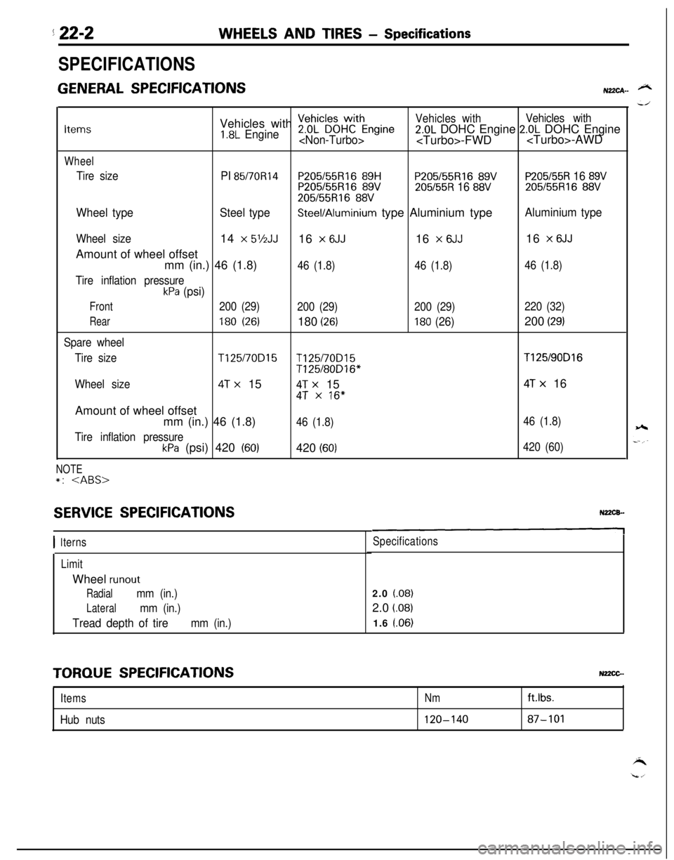
SPECIFICATIONS
GENERAL SPECIFICATIONSN22CA- @NVehicles with
~eDhL”~~HWCthEngineVehicles withVehicles withItems1.8L Engine2.0L DOHC Engine 2.0L DOHC Engine
Wheel
Tire sizePI 85/70R14P205155Rl6 89HP205/55R16 89VP205/55R 16 89VP205155R16 89V205/55R 16 88V205/55R16 88V
205/55R16 88V
Wheel typeSteel typeSteel/Aluminium type Aluminium typeAluminium type
Wheel size14 x 5’/2JJ16 x 6JJ16 x 6JJ16 x 6JJAmount of wheel offset
mm (in.) 46 (1.8)
46 (1.8)46 (1.8)46 (1.8)
Tire inflation pressure
kPa (psi)
Front200 (29)
200 (29)200 (29)220 (32)
Rear180 (26)180 (26)180 (26)200 (29)
Spare wheel
Tire size
T125/70D15T125/70D15T125/90D16
T125/80D16*
Wheel size
4T x 154T x 154T x 16
4T x 16”Amount of wheel offset
mm (in.) 46 (1.8)
46 (1.8)46 (1.8)
Tire inflation pressure
kPa (psi) 420 (60)420 (60)420 (60)
NOTE*:
SERVICE SPECIFICATIONS
I 1terns
LimitWheel
runout
Radialmm (in.)
Lateralmm (in.)
Tread depth of tiremm (in.)
Specifications2.0
(.08)2.0
i.08)1.6 l.06)
TORQUE SPECIFICATIONSNz2cG-
ItemsNm
Hub nuts120-140ftlbs.87-101
Page 1042 of 1216
22-4WHEELS AND TIRES - Service Adjustment Procedures
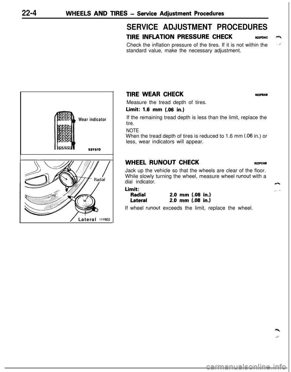
Wear indicator
53r510
/ Lateral 11Y602
SERVICE ADJUSTMENT PROCEDURES
TIRE INFLATION PRESSURE CHECKN2ZFOACCheck the inflation pressure of the tires. If it is not within the
standard value, make the necessary adjustment.
TIRE WEAR CHECKN2zFsABMeasure the tread depth of tires.Limit:
1.6 mm (.06 in,)If the remaining tread depth is less than the limit, replace the
tire.
NOTEWhen the tread depth of tires is reduced to 1.6 mm
(.06 in.) or
less, wear indicators will appear.
WHEEL RUNOUT CHECKNZ2FCA5Jack up the vehicle so that the wheels are clear of the floor.
While slowly turning the wheel, measure wheel
runout with a
dial indicator.Limit:
Radial2.0 mm (.08 in.)
Lateral2.0 mm (.08 in.)If wheel
runout exceeds the limit, replace the wheel.