engine overheat MITSUBISHI ECLIPSE 1991 Service Manual
[x] Cancel search | Manufacturer: MITSUBISHI, Model Year: 1991, Model line: ECLIPSE, Model: MITSUBISHI ECLIPSE 1991Pages: 1216, PDF Size: 67.42 MB
Page 29 of 1216
INTRODUCTION AND MASTER TROUBLESHOOTING - Mast& Tro6blerhootbia
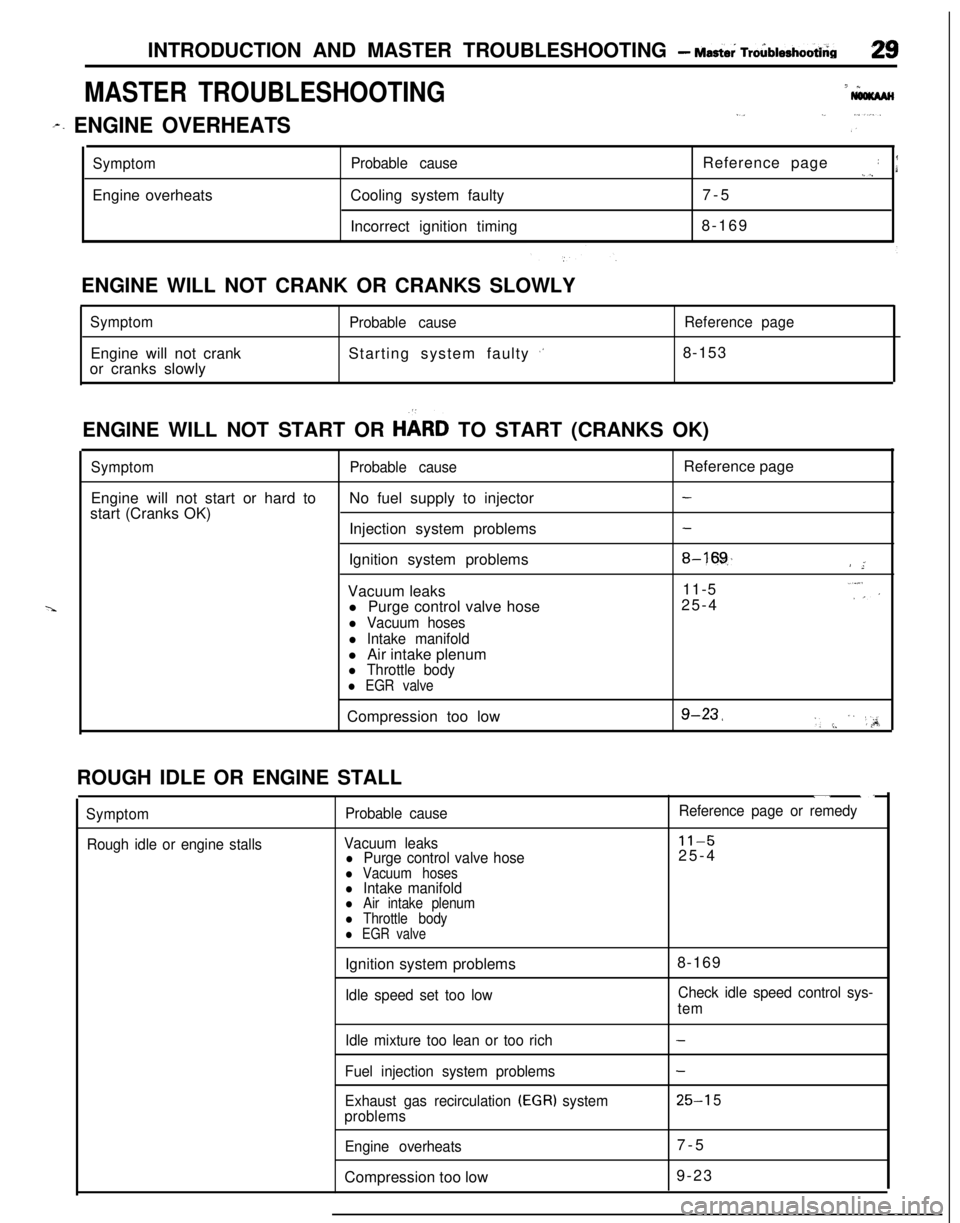
MASTER TROUBLESHOOTING7 *
I,._ ,...
r. ENGINE OVERHEATSi ”
SymptomEngine overheatsProbable causeCooling system faulty
Incorrect ignition timingReference page: I._),7-5
8-169
ENGINE WILL NOT CRANK OR CRANKS SLOWLY
SymptomEngine will not crank
or cranks slowlyProbable causeStarting system faulty
,’
Reference page8-153
ENGINE WILL NOT START OR
HbRD TO START (CRANKS OK)
SymptomProbable causeReference page
Engine will not start or hard toNo fuel supply to injector
-start (Cranks OK)
Injection system problems
-Ignition system problems
8-16!$/ ”;Vacuum leaks11-5..“,:’l Purge control valve hose25-4
l Vacuum hoses
l Intake manifoldl Air intake plenum
l Throttle body
l EGR valveCompression too low
g-23,‘, :. ” ‘,;A;ROUGH IDLE OR ENGINE STALL
Symptom
Rough idle or engine stallsProbable cause
Vacuum leaks
l Purge control valve hosel Vacuum hosesl Intake manifoldl Air intake plenuml Throttle bodyl EGR valve
“. ._
Reference page or remedy
11-525-4
Ignition system problems
Idle speed set too low8-169Check idle speed control sys-
tem
Idle mixture too lean or too rich
Fuel injection system problems
Exhaust gas recirculation
(EGR) system
problems
Engine overheatsCompression too low
-
-
25-l 57-5
9-23
Page 30 of 1216
30INTRODUCTION AND MASTER TROUBLESHOOTING - Master Troubleshooting
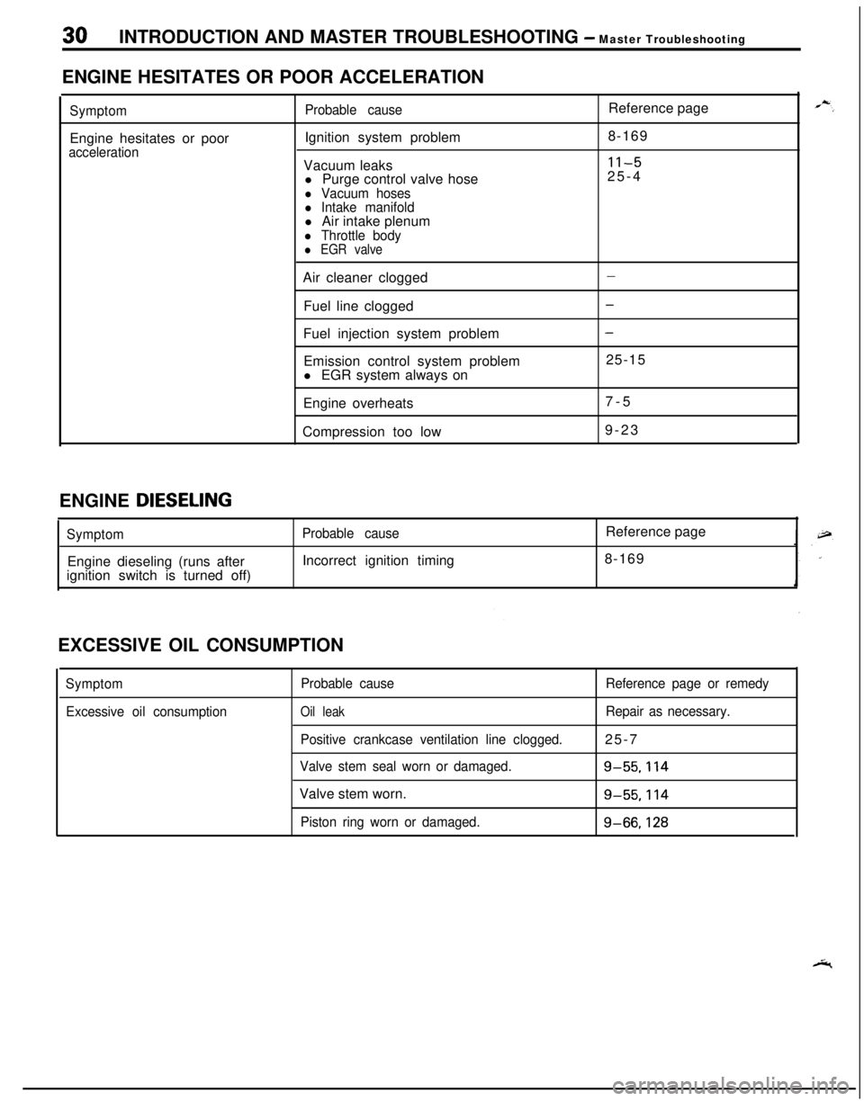
ENGINE HESITATES OR POOR ACCELERATION
SymptomEngine hesitates or poor
accelerationProbable causeIgnition system problem
Vacuum leaks
l Purge control valve hose
l Vacuum hosesl Intake manifoldl Air intake plenum
l Throttle bodyl EGR valveReference page
8-169
11-525-4
Air cleaner clogged
Fuel line clogged
Fuel injection system problem
Emission control system problem
l EGR system always on
Engine overheats
Compression too low
-
-
-25-15
7-5
9-23
ENGINE
DIESELING
SymptomEngine dieseling (runs after
ignition switch is turned off)Probable causeIncorrect ignition timingReference page
8-169
EXCESSIVE OIL CONSUMPTION
Symptom
Excessive oil consumptionProbable cause
Oil leak
Positive crankcase ventilation line clogged.
Valve stem seal worn or damaged.Valve stem worn.
Piston ring worn or damaged.Reference page or remedy
Repair as necessary.25-7
g-55.114
g-55.114
g-66,128
Page 249 of 1216
7-l
COOLING
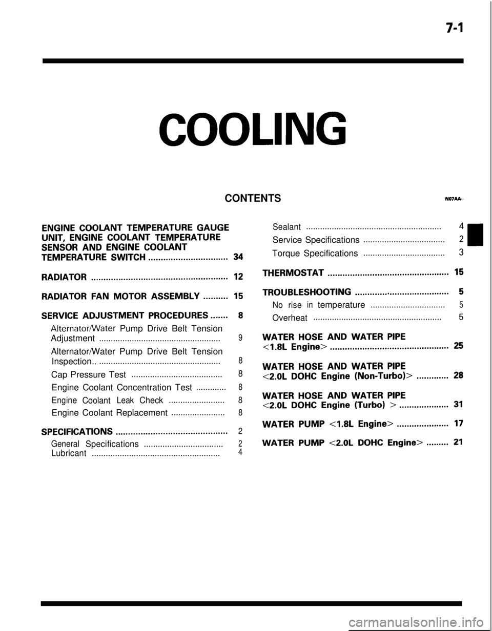
CONTENTS
ENGINE COOLANT TEMPERATURE GAUGEUNIT,
ENGINE COOLANT TEMPERATURE
SENSOR AND ENGINE COOLANT
TEMPERATURE SWITCH................................34
RADIATOR.......................................................12
RADIATORFANMOTOR ASSEMBLY..........15
SERVICE ADJUSTMENT PROCEDURES.......8
Alternatormater Pump Drive Belt Tension
Adjustment
....................................................9Alternator/Water Pump Drive Belt Tension
Inspection..
....................................................8Cap Pressure Test
.......................................8Engine Coolant Concentration Test
.............8
EngineCoolantLeakCheck........................8Engine Coolant Replacement
.......................8
SPECIFICATIONS.............................................2
GeneralSpecifications..................................2
Lubricant.......................................................4
Sealant..........................................................4Service Specifications
...................................2Torque Specifications
...................................3THERMOSTAT
.................................................15
TROUBLESHOOTING......................................5
Noriseintemperature................................5
Overheat.......................................................5
WATER HOSE AND WATER PIPE
<1.8L Engine>................................................25
WATER HOSE AND WATER PIPE
<2.0LDOHCEngine(Non-Turbo)>.............28
WATER HOSE AND WATER PIPE
<2.0LDOHCEngine(Turbo)>....................31
WATERPUMP<1.8LEngine>.....................17
WATER PUMP <2.0L DOHC Engine>.........21
Page 253 of 1216

COOLING - Troubleshootina7-5
TRO,UBLESHOOTlNG
Symptom
OverheatProbable causeInsufficient engine coolant
Too high an anti-freeze concentrationRemedy
Replenish
Correct anti-freeze
concentration
Loose or broken drive belt
Replace
Inoperative electric cooling fan
Faulty thermosensor
Replace
Faulty electrical motorReplace
Faulty radiator fan relayReplace
Damaged or blocked (insufficiently ventilated) radiator finsCorrect
Water leaks
Damaged radiator core joint
Replace
Corroded or cracked hosesReplace
(radiator hose, heater hose, etc.)
Loose bolt or leaking gasket in water outlet fitting
(thermostat)
Loose water pump mounting bolt or leaking gasket
Faulty cap valve or setting of spring
Loose intake manifold bolts or leaking from gasket
Cracked intake manifold
Faulty automatic transaxle oil cooler operation
Blocked or collapsed hose and pipe
Loose hose and pipe connection
Faulty thermostat operation
Faulty water pump operation
Water passage clogged with slime or rust deposit or
foreign substanceCorrect or replace
Correct or replace
Replace
Retorque bolts or replace
gasket
Replace
Replace
Correct
Replace
Replace
Clean
Jo rise in temperatureFaulty thermostatReplace
Page 1156 of 1216
24-12 HEATERS AND AIR CONDITIONING - Service Adjustment Procedures
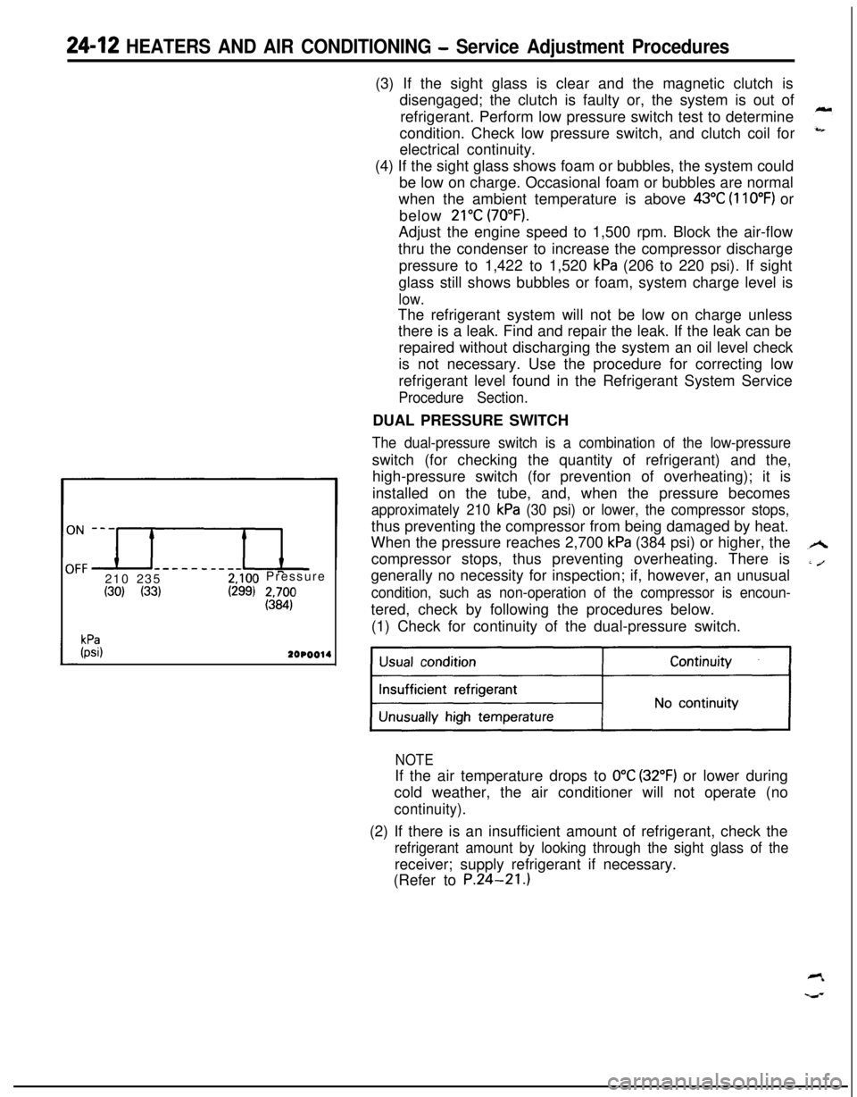
------__--210 2352,100 Pressure
(30) (33)(299) 2&
kPa(psi)2OPOO14(3) If the sight glass is clear and the magnetic clutch is
disengaged; the clutch is faulty or, the system is out of
refrigerant. Perform low pressure switch test to determine
condition. Check low pressure switch, and clutch coil for
electrical continuity.
(4) If the sight glass shows foam or bubbles, the system could
be low on charge. Occasional foam or bubbles are normal
when the ambient temperature is above
43°C (110°F) or
below
21°C (70°F).Adjust the engine speed to 1,500 rpm. Block the air-flow
thru the condenser to increase the compressor discharge
pressure to 1,422 to 1,520
kPa (206 to 220 psi). If sight
glass still shows bubbles or foam, system charge level is
low.The refrigerant system will not be low on charge unless
there is a leak. Find and repair the leak. If the leak can be
repaired without discharging the system an oil level check
is not necessary. Use the procedure for correcting low
refrigerant level found in the Refrigerant System Service
Procedure Section.DUAL PRESSURE SWITCH
The dual-pressure switch is a combination of the low-pressureswitch (for checking the quantity of refrigerant) and the,
high-pressure switch (for prevention of overheating); it is
installed on the tube, and, when the pressure becomes
approximately 210 kPa (30 psi) or lower, the compressor stops,thus preventing the compressor from being damaged by heat.
When the pressure reaches 2,700
kPa (384 psi) or higher, the
compressor stops, thus preventing overheating. There is
generally no necessity for inspection; if, however, an unusual
condition, such as non-operation of the compressor is encoun-tered, check by following the procedures below.
(1) Check for continuity of the dual-pressure switch.
NOTEIf the air temperature drops to
0°C (32°F) or lower during
cold weather, the air conditioner will not operate (no
continuity).(2) If there is an insufficient amount of refrigerant, check the
refrigerant amount by looking through the sight glass of thereceiver; supply refrigerant if necessary.
(Refer to P.24-21.)
Page 1157 of 1216
HEATERS AND AIR CONDITIONING - Service Adjustment Procedures 249*I3
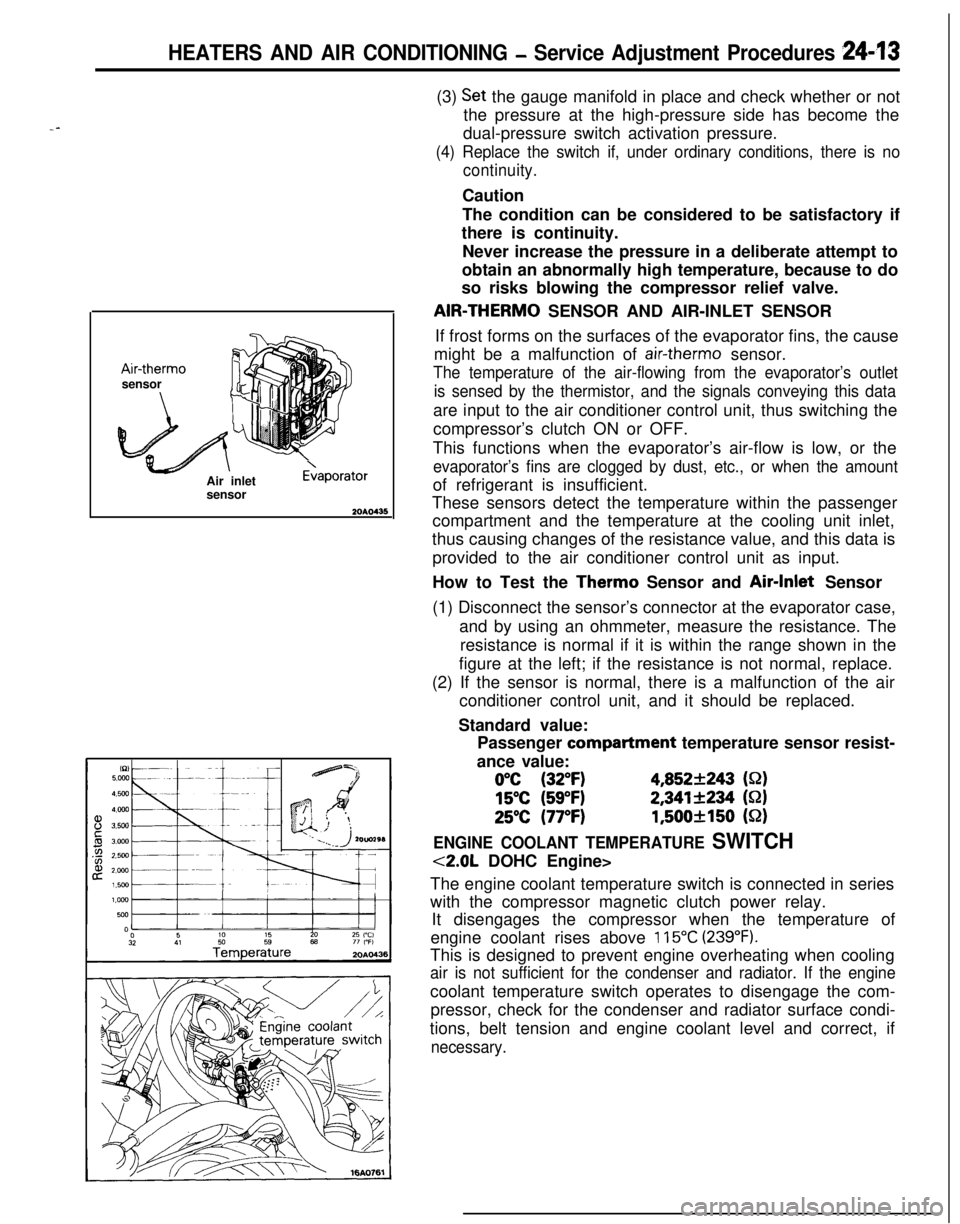
--Air-therm0
sensor
Air inlet
sensor
E>aporator(3)
Set the gauge manifold in place and check whether or not
the pressure at the high-pressure side has become the
dual-pressure switch activation pressure.
(4) Replace the switch if, under ordinary conditions, there is no
continuity.Caution
The condition can be considered to be satisfactory if
there is continuity.
Never increase the pressure in a deliberate attempt to
obtain an abnormally high temperature, because to do
so risks blowing the compressor relief valve.AIR-THERM0 SENSOR AND AIR-INLET SENSOR
If frost forms on the surfaces of the evaporator fins, the cause
might be a malfunction of
air-therm0 sensor.
The temperature of the air-flowing from the evaporator’s outlet
is sensed by the thermistor, and the signals conveying this dataare input to the air conditioner control unit, thus switching the
compressor’s clutch ON or OFF.
This functions when the evaporator’s air-flow is low, or the
evaporator’s fins are clogged by dust, etc., or when the amountof refrigerant is insufficient.
These sensors detect the temperature within the passenger
compartment and the temperature at the cooling unit inlet,
thus causing changes of the resistance value, and this data is
provided to the air conditioner control unit as input.
How to Test the Therm0 Sensor and Air-Inlet Sensor
(1) Disconnect the sensor’s connector at the evaporator case,
and by using an ohmmeter, measure the resistance. The
resistance is normal if it is within the range shown in the
figure at the left; if the resistance is not normal, replace.
(2) If the sensor is normal, there is a malfunction of the air
conditioner control unit, and it should be replaced.
Standard value:
Passenger compartment temperature sensor resist-
ance value:
0°C (32°F)4,852+243 (S-2)
15°C (59°F)2,341+234 (S-2)
25°C (77°F)1,500+150 (52)
ENGINE COOLANT TEMPERATURE SWITCH
<2.0L DOHC Engine>
The engine coolant temperature switch is connected in series
with the compressor magnetic clutch power relay.
It disengages the compressor when the temperature of
engine coolant rises above
115°C (239°F).This is designed to prevent engine overheating when cooling
air is not sufficient for the condenser and radiator. If the enginecoolant temperature switch operates to disengage the com-
pressor, check for the condenser and radiator surface condi-
tions, belt tension and engine coolant level and correct, if
necessary.
Page 1216 of 1216
25-20Exhaust Gas Recirculation (EGR) System/EMISSION CONTROL SYSTEMS - ‘catalytic Converter(5) Measure the resistance between the terminals
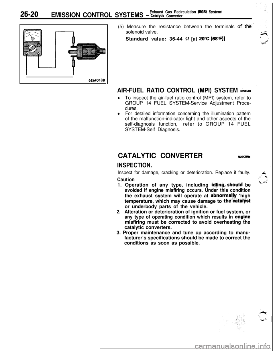
of- the
Q [at 20°C (68OF)l
6EM0188
AIR-FUEL RATIO CONTROL (MPI) SYSTEM &CAD
lTo inspect the air-fuel ratio control (MPI) system, refer to
GROUP 14 FUEL SYSTEM-Service Adjustment Proce-
dures.
lFor detailed information concerning the illumination patternof the malfunction-indicator light and other aspects of the
self-diagnosis function,refer to GROUP 14 FUEL
SYSTEM-Self Diagnosis.
CATALYTIC CONVERTERN25lCBHa
INSPECTION.
Inspect for damage, cracking or deterioration. Replace if faulty.
Caution1. Operation of any type, including
idjing, should be
avoided if engine misfiring occurs. Under this conditionthe exhaust system will operate at abnormally ‘high
temperature, which may cause damage to
the”Catalystor underbody parts of the vehicle.
2.Alteration or deterioration of ignition or fuel system, or
any type of operating condition which results in enghtemisfiring must be corrected to avoid overheating the
catalytic converters.
3. Proper maintenance and tune up according to manu-
facturer’s specifications should be made to correct the
conditions as soon as possible.