height adjustment MITSUBISHI ECLIPSE 1991 Service Manual
[x] Cancel search | Manufacturer: MITSUBISHI, Model Year: 1991, Model line: ECLIPSE, Model: MITSUBISHI ECLIPSE 1991Pages: 1216, PDF Size: 67.42 MB
Page 124 of 1216
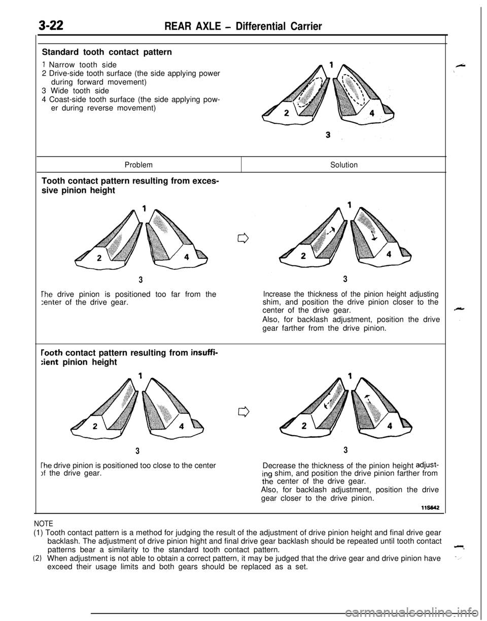
3-22REAR AXLE - Differential CarrierStandard tooth contact pattern
1 Narrow tooth side
2 Drive-side tooth surface (the side applying power
during forward movement)
3 Wide tooth side
4 Coast-side tooth surface (the side applying pow-
er during reverse movement)
ProblemTooth contact pattern resulting from exces-
sive pinion heightSolution
3
The drive pinion is positioned too far from the:enter of the drive gear.
3
Increase the thickness of the pinion height adjustingshim, and position the drive pinion closer to the
center of the drive gear.
Also, for backlash adjustment, position the drive
gear farther from the drive pinion.
rooth contact pattern resulting from insuffi-
:ient pinion height
3
The drive pinion is positioned too close to the centerIf the drive gear.
3Decrease the thickness of the pinion height
adjust-ing shim, and position the drive pinion farther from
ihe center of the drive gear.
Also, for backlash adjustment, position the drive
gear closer to the drive pinion.
115642
NOTE(1) Tooth contact pattern is a method for judging the result of the adjustment of drive pinion height and final drive gear
backlash. The adjustment of drive pinion hight and final drive gear backlash should be repeated until tooth contact
patterns bear a similarity to the standard tooth contact pattern.
(2)When adjustment is not able to obtain a correct pattern, it may be judged that the drive gear and drive pinion have
exceed their usage limits and both gears should be replaced as a set.
Page 125 of 1216
REAR AXLE - Differential Carrier3-23
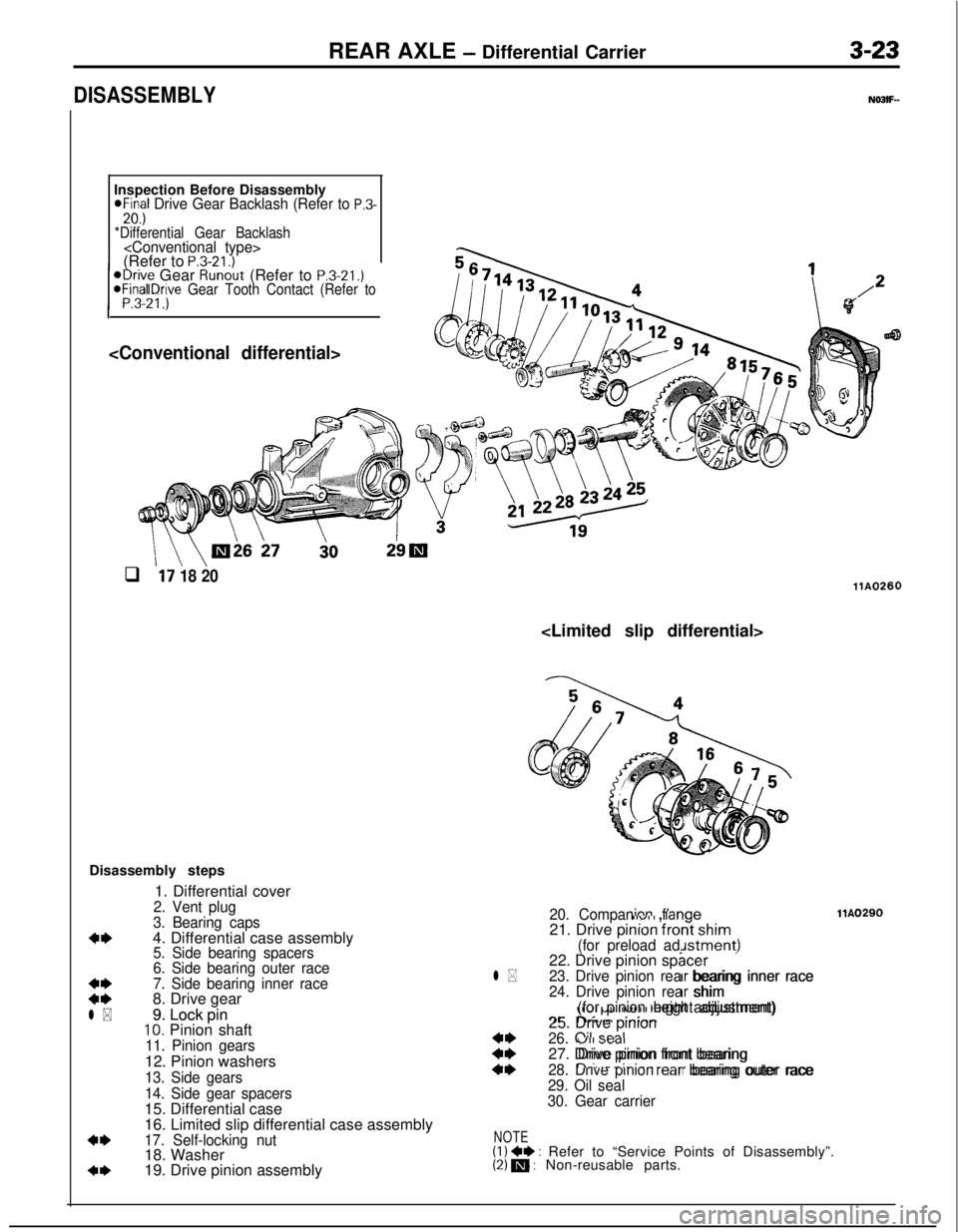
DISASSEMBLYInspection Before Disassembly
@Final Drive Gear Backlash (Refer to P.3-20.)*Differential Gear Backlash
/ ;3-21.)’1
@Drive Gear Runout (Refer to P.3-21.)aFInal Drove Gear Tooth Contact (Refer to
\ \\Oi6 27i0
q l7 18 20llA0260
Disassembly steps
1. Differential cover
2. Vent plug
3. Bearing caps
*I)4. Differential case assembly5. Side bearing spacers
6. Side bearing outer race
:z
7. Side bearing inner race8. Drive gear
l * l *9. Lock pin 9. Lock pin10. Pinion shaft11. Pinion gears12. Pinion washers
13. Side gears
14. Side gear spacers15. Differential case
16. Limited slip differential case assembly
*I)17. Self-locking nut18. Washer
4*19. Drive pinion assembly
20. Companion flangellvlI , ,,,igellA0290llA0290
21. Drive pinion front shim-:-- ‘--nt shim
(for preload adjustment)Jstment)22. Drive pinion spacer3cerl *23. Drive pinion rear bearing inner racerr bearing inner race
24. Drive pinion rear shimrr shim,Ivl PJ” llUl I I IcIyIit adjustment)(for pinion height adjustment)?Cl3.r;. I,-. ..:..;A-25. Drive pinion
::
26. Oil seal“II >twI27. Drive pinion front bearingDrive pinion front bearing
4*28. Drive pinion rear bearing outer racen-‘..- -‘-‘-- --lr bearing outer race
29. Oil seal
30. Gear carrier
NOTE(1) +I) : Refer to “Service Points of Disassembly”.(2) m : Non-reusable parts.
Page 128 of 1216
3-26REAR AXLE - Differential Carrier
REASSEMBLYN0311-
Nm*B-43 ft.lbs.*
80-90 Nm*58-65 ft.lbs.*
11 BOO86Differential gear setFinal drive gear set
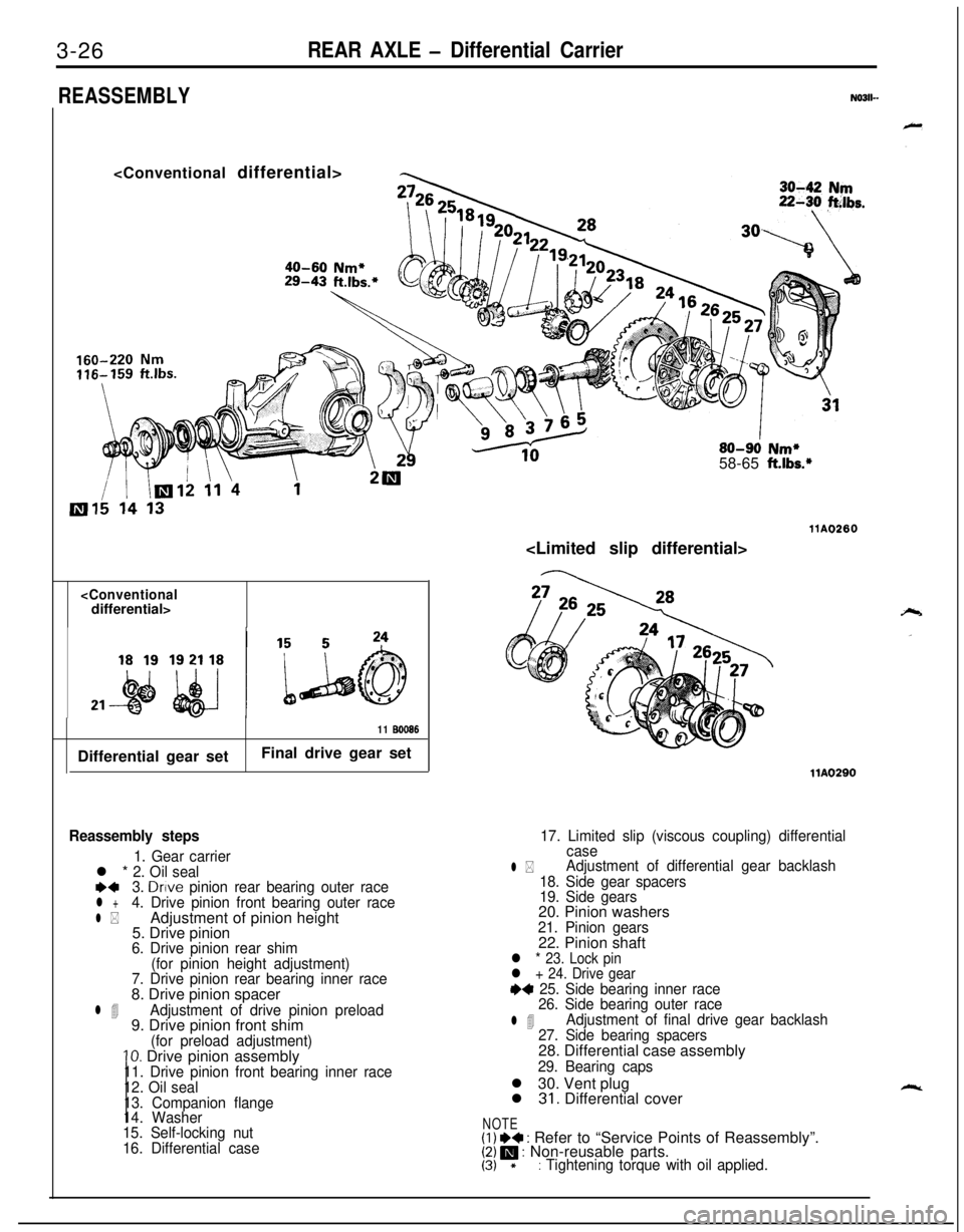
Reassembly steps
1. Gear carrierl * 2. Oil seale+3. Drive pinion rear bearing outer racel +4. Drive pinion front bearing outer race
l *Adjustment of pinion height
5. Drive pinion
6. Drive pinion rear shim
(for pinion height adjustment)
7. Drive pinion rear bearing inner race8. Drive pinion spacer
l 4Adjustment of drive pinion preload9. Drive pinion front shim
(for preload adjustment)10. Drive pinion assembly11. Drive pinion front bearing inner race
12. Oil seal
13. Companion flange
14. Washer
15. Self-locking nut
16. Differential case
17. Limited slip (viscous coupling) differential
case
l *Adjustment of differential gear backlash
18. Side gear spacers
19. Side gears20. Pinion washers
21. Pinion gears22. Pinion shaft
l * 23. Lock pin
l + 24. Drive gear
+4 25. Side bearing inner race
26. Side bearing outer race
l 4Adjustment of final drive gear backlash
27. Side bearing spacers28. Differential case assembly
29. Bearing capsl 30. Vent plug
l
31. Differential cover
NOTE(I) I)+ : Refer to “Service Points of Reassembly”.[Z!/ m : Non-reusable parts.*: Tightening torque with oil applied.
Page 129 of 1216
REAR AXLE - Differential Carrier3-27
llK010
71
llY181llY182
.MB990836(MB990835)
llrm3
V223
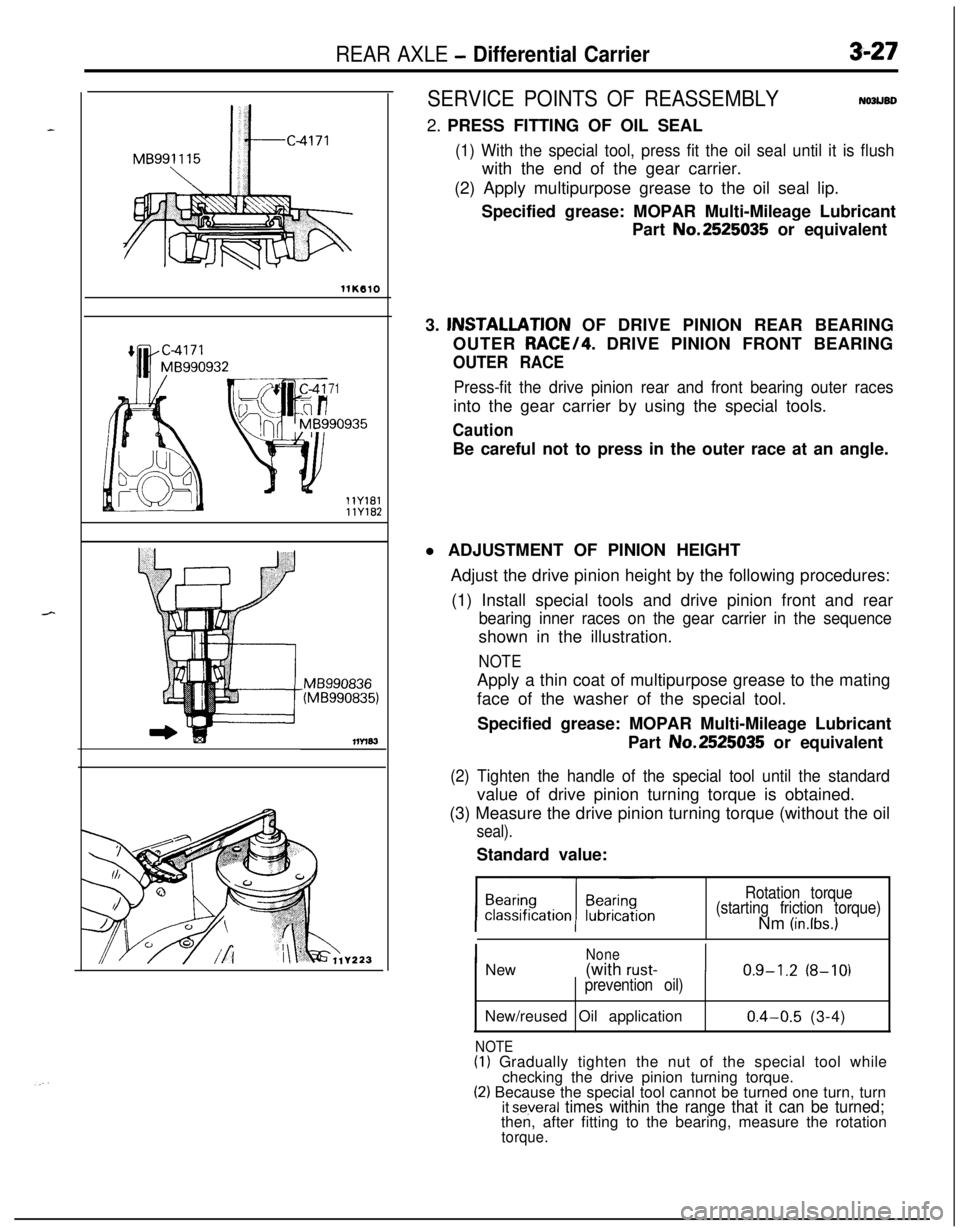
SERVICE POINTS OF REASSEMBLYNOJUBD2. PRESS FITTING OF OIL SEAL
(1) With the special tool, press fit the oil seal until it is flushwith the end of the gear carrier.
(2) Apply multipurpose grease to the oil seal lip.
Specified grease: MOPAR Multi-Mileage Lubricant
Part No.2525035 or equivalent
3. lNSTALLATlON OF DRIVE PINION REAR BEARING
OUTER RACE/4. DRIVE PINION FRONT BEARING
OUTER RACE
Press-fit the drive pinion rear and front bearing outer racesinto the gear carrier by using the special tools.
CautionBe careful not to press in the outer race at an angle.
l ADJUSTMENT OF PINION HEIGHT
Adjust the drive pinion height by the following procedures:
(1) Install special tools and drive pinion front and rear
bearing inner races on the gear carrier in the sequenceshown in the illustration.
NOTEApply a thin coat of multipurpose grease to the mating
face of the washer of the special tool.
Specified grease: MOPAR Multi-Mileage Lubricant
Part No.2525035 or equivalent
(2) Tighten the handle of the special tool until the standardvalue of drive pinion turning torque is obtained.
(3) Measure the drive pinion turning torque (without the oil
seal).Standard value:
Rotation torque
(starting friction torque)Nm
(in.lbs.)
I
NoneNew(with rust-I0.9-1.2 (8-10)prevention oil)New/reused Oil application
NOTE
0.4-0.5 (3-4)(I) Gradually tighten the nut of the special tool while
checking the drive pinion turning torque.
(2) Because the special tool cannot be turned one turn, turnit several times within the range that it can be turned;then, after fitting to the bearing, measure the rotation
torque.
Page 181 of 1216
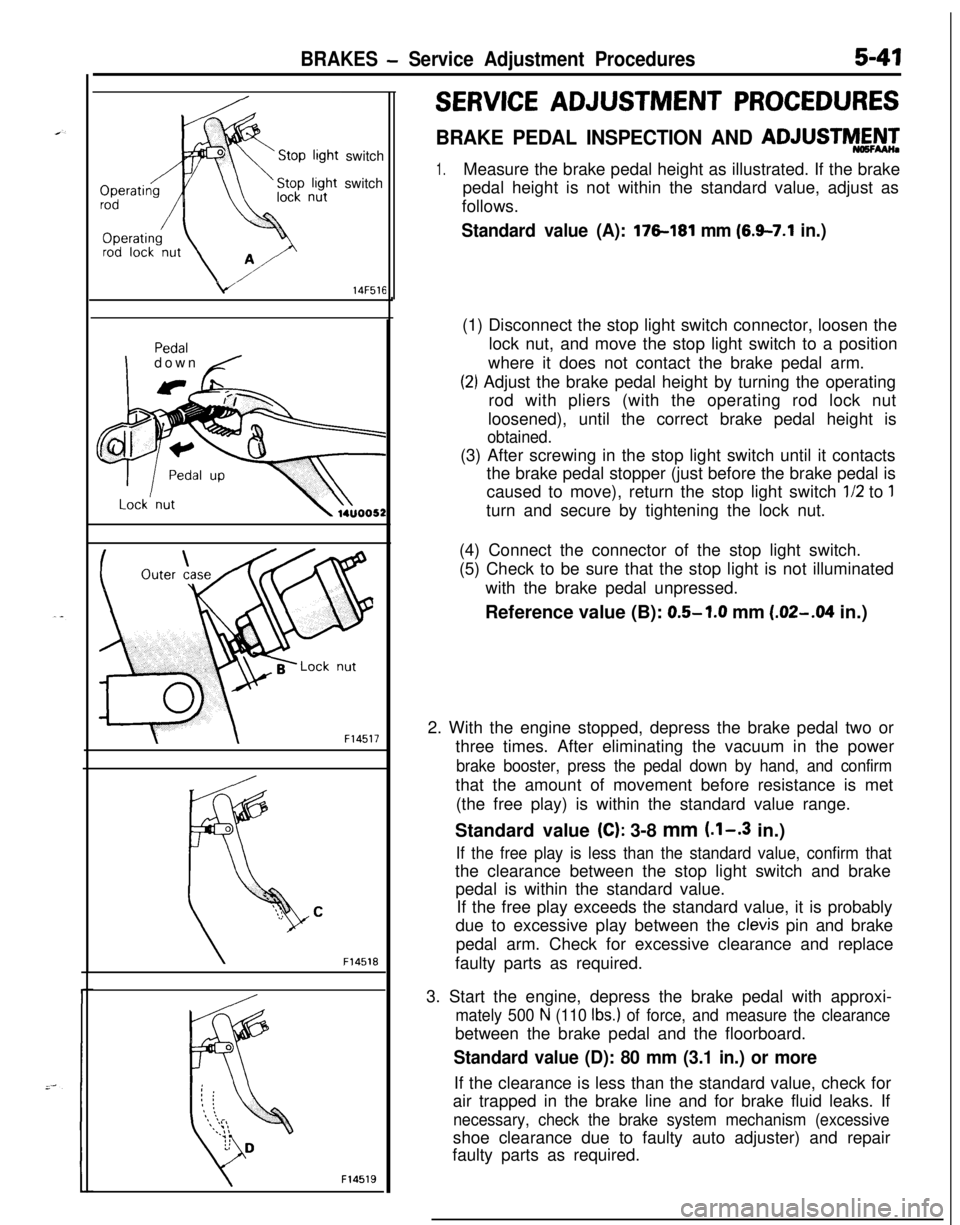
BRAKES - Service Adjustment Procedures5-47switch
switch
v14F516
Idown ,./
F14517
F14518
F14519
SERVICE ADJUSTMENT PROCEDURES
BRAKE PEDAL INSPECTION AND ADJUSTM&g
1.Measure the brake pedal height as illustrated. If the brake
pedal height is not within the standard value, adjust as
follows.
Standard value (A): 176181 mm (6.9-7.1 in.)(1) Disconnect the stop light switch connector, loosen the
lock nut, and move the stop light switch to a position
where it does not contact the brake pedal arm.
(2) Adjust the brake pedal height by turning the operating
rod with pliers (with the operating rod lock nut
loosened), until the correct brake pedal height is
obtained.(3) After screwing in the stop light switch until it contacts
the brake pedal stopper (just before the brake pedal is
caused to move), return the stop light switch
l/2 to 1turn and secure by tightening the lock nut.
(4) Connect the connector of the stop light switch.
(5) Check to be sure that the stop light is not illuminated
with the brake pedal unpressed.
Reference value (B): 0.5-1.0 mm
(.02-M in.)
2. With the engine stopped, depress the brake pedal two or
three times. After eliminating the vacuum in the power
brake booster, press the pedal down by hand, and confirmthat the amount of movement before resistance is met
(the free play) is within the standard value range.
Standard value
(C): 3-8 mm (.l-.3 in.)
If the free play is less than the standard value, confirm thatthe clearance between the stop light switch and brake
pedal is within the standard value.
If the free play exceeds the standard value, it is probably
due to excessive play between the
clevis pin and brake
pedal arm. Check for excessive clearance and replace
faulty parts as required.
3. Start the engine, depress the brake pedal with approxi-
mately 500 N (110 Ibs.) of force, and measure the clearancebetween the brake pedal and the floorboard.
Standard value (D): 80 mm (3.1 in.) or moreIf the clearance is less than the standard value, check for
air trapped in the brake line and for brake fluid leaks. If
necessary, check the brake system mechanism (excessiveshoe clearance due to faulty auto adjuster) and repair
faulty parts as required.
Page 183 of 1216
BRAKES - Service Adjustment Procedures5-43When engine is
stoppedNo good
0
wtwo061
VV;Videngine is
t4uoo60
Caution
If the number of brake lever notches engaged is less
than the standard value, the cable has been pulledexcessively, and failure of the automatic adjuster
mechanism will result. Be sure tti adjust it to within the
standard value.(6) After making the adjustment, check to be sure that there is
no play between the adjusting nut and the pin. Also check
to be sure that the adjusting nut is securely held at the nut
holder.(7) After adjusting the lever stroke, jack up the rear of the
vehicle.(8) With the parking brake lever in the released position, turn
the rear wheel to confirm that the rear brakes are not
dragging.
PARKING BRAKE SWITCH CHECKN05FDAB
(1) Disconnect the connector of the parking brake switch, and
connect an ohmmeter to the parking brake switch and the
switch installation bolt.
(2) The parking brake switch is good if there is continuity whenthe parking brake lever is pulled and there is no continuity
when it is returned.
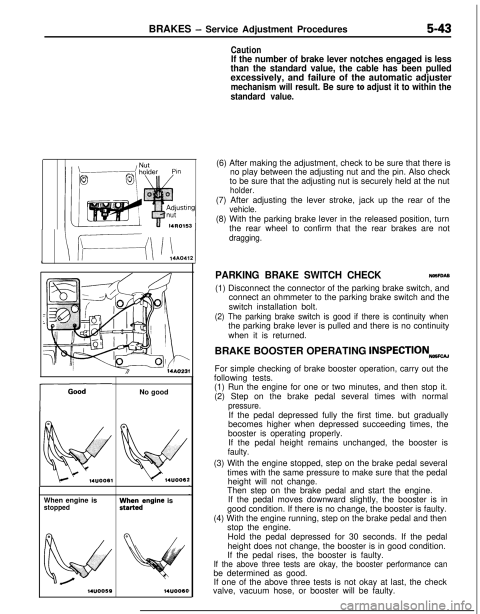
BRAKE BOOSTER OPERATING
lNSPECTIONNoSFcuFor simple checking of brake booster operation, carry out the
following tests.
(1) Run the engine for one or two minutes, and then stop it.
(2) Step on the brake pedal several times with normal
pressure.If the pedal depressed fully the first time. but gradually
becomes higher when depressed succeeding times, the
booster is operating properly.
If the pedal height remains unchanged, the booster is
faulty.(3) With the engine stopped, step on the brake pedal several
times with the same pressure to make sure that the pedal
height will not change.
Then step on the brake pedal and start the engine.
If the pedal moves downward slightly, the booster is in
good condition. If there is no change, the booster is faulty.
(4) With the engine running, step on the brake pedal and then
stop the engine.
Hold the pedal depressed for 30 seconds. If the pedal
height does not change, the booster is in good condition.
If the pedal rises, the booster is faulty.
If the above three tests are okay, the booster performance canbe determined as good.
If one of the above three tests is not okay at last, the check
valve, vacuum hose, or booster will be faulty.
Page 235 of 1216
CLUTCH - Service Adjustment Procedures6-5Clutch pedal height
b
AClutch pedal clevis
pin play
08YO43Vehicles without
auto-cruise control
systemVehicles with
auto-cruise control
08A0025I
Clutch pedal free pIa\
08YO43
Distance between the
clutch pedal and thefirewall
when theclutch is disengaged
SERVICE ADJUSTMENT PROCEDURES
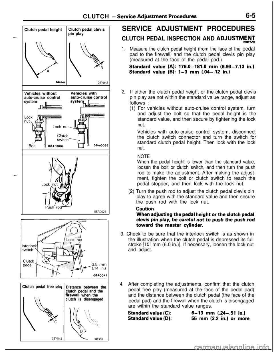
CLUTCH PEDAL INSPECTION AND ADJUSTMY’,
1.Measure the clutch pedal height (from the face of the pedalpad to the
firewall) and the clutch pedal clevis pin play
(measured at the face of the pedal pad.)
Standard value (A): 176.0-181.0 mm (6.93-7.13 in.)
Standard value (B): l-3 mm (.04-.12 in.)
2.If either the clutch pedal height or the clutch pedal clevis
pin play are not within the standard value range, adjust as
follows
:(1) For vehicles without auto-cruise control system, turn
and adjust the bolt so that the pedal height is the
standard value, and then secure by tightening the lock
nut.Vehicles with auto-cruise control system, disconnect
the clutch switch connector and turn the switch for
standard clutch pedal height. Then lock with the lock
nut.
NOTE
When the pedal height is lower than the standard value,
loosen the bolt or clutch switch, and then turn the pushrod to make the adjustment. After making the adjust-
ment, tighten the bolt or clutch switch to reach the
pedal stopper, and then lock with the lock nut.
(2) Turn the push rod to adjust the clutch pedal clevis pin
play to agree with the standard value and then secure
the push rod with the lock nut.
CautionWhen adjusting the
pedal height or the clutch pedal
clevis pin play, be careful not to push the push rodtoward the master
cylinder.3. Check to be sure that the interlock switch is as shown in
the illustration when the clutch pedal is depressed its full
stroke
[151 mm (6.0 in.)]. If necessary, loosen the lock nut
and adjust.
4.After completing the adjustments, confirm that the clutch
pedal free play (measured at the face of the pedal pad)
and the distance between the clutch pedal (the face of the
pedal pad) and the
firewall when the clutch is disengaged
are within the standard value ranges.
Standard value (C):6-13 mm (.24-.51 in.)
Standard value (D):55 mm (2.2 in.) or more
Page 292 of 1216
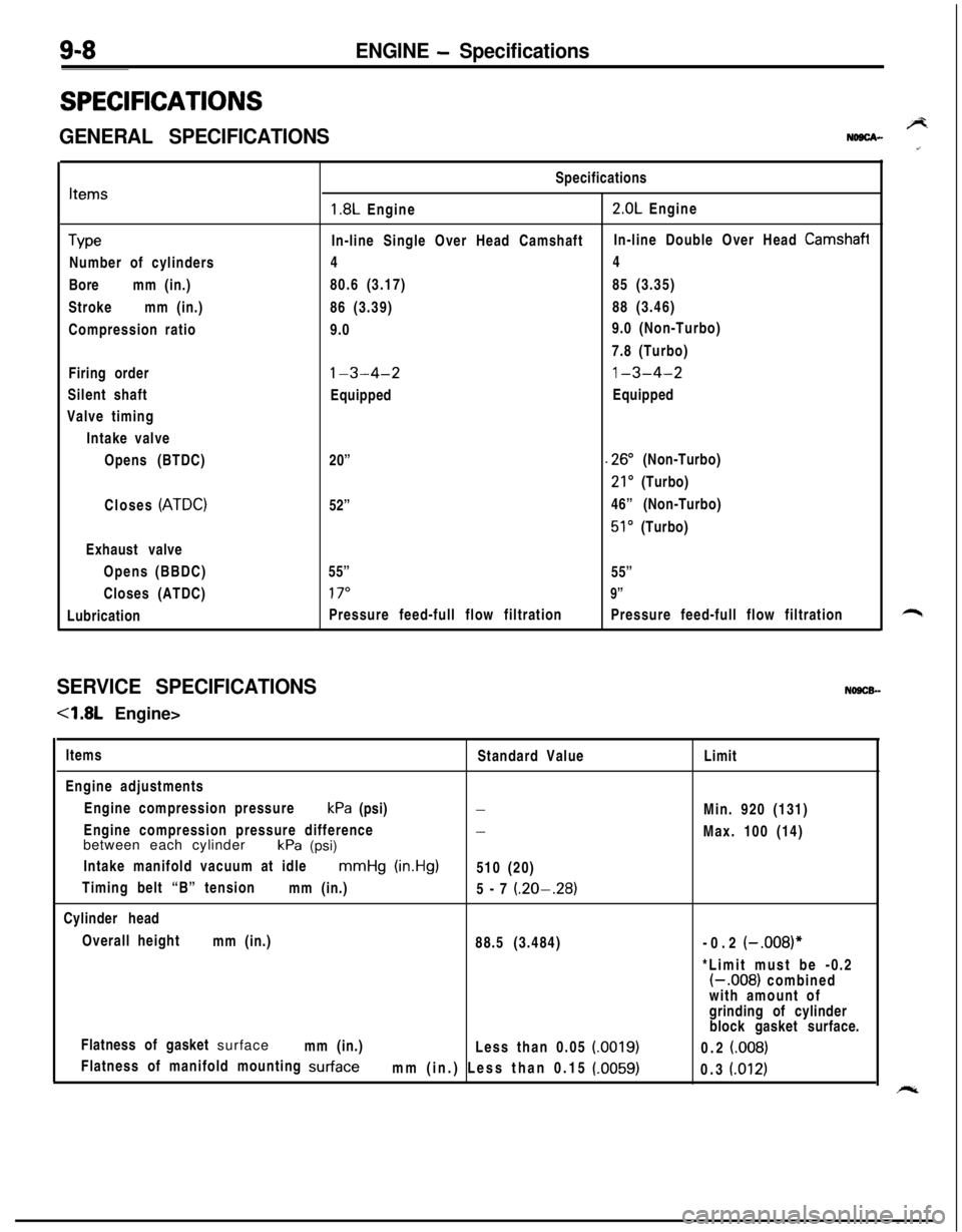
9-8ENGINE - Specifications
SPECIFICATIONS
GENERAL SPECIFICATIONSBNDBCA-
Items
TypeNumber of cylinders
Boremm (in.)
Strokemm (in.)
Compression ratio
Firing order
Silent shaft
Valve timing
Intake valve
Opens (BTDC)
Closes
(ATDC)Exhaust valve
Opens (BBDC)
Closes (ATDC)
LubricationSpecifications
1.8L Engine2.0L Engine
In-line Single Over Head CamshaftIn-line Double Over Head
Camshafi44
80.6 (3.17)85 (3.35)
86 (3.39)88 (3.46)
9.09.0 (Non-Turbo)
7.8 (Turbo)
l-3-4-21-3-4-2EquippedEquipped
20”
.26” (Non-Turbo)
21’ (Turbo)
52”46” (Non-Turbo)
51’ (Turbo)
55”
55”
17”9”Pressure feed-full flow filtrationPressure feed-full flow filtration
SERVICE SPECIFICATIONSNOSCB-
-4.8L Engine>
Items
Standard Value
Engine adjustments
Engine compression pressurekPa (psi)
-Engine compression pressure difference
-between each cylinder
kPa (psi)
Intake manifold vacuum at idle
mmHg (in.Hg)510 (20)
Timing belt “B” tension
mm (in.)
5-7
(.20-.28)Cylinder head
Overall height
mm (in.)
88.5 (3.484)
Flatness of gasket surface
mm (in.)
Less than 0.05
(0019)Flatness of manifold mounting
surfacemm (in.) Less than 0.15 (.0059)Limit
Min. 920 (131)
Max. 100 (14)
-0.2
(-.008)**Limit must be -0.2
(-.008) combined
with amount of
grinding of cylinder
block gasket surface.
0.2
(008)0.3
(.012)
Page 297 of 1216
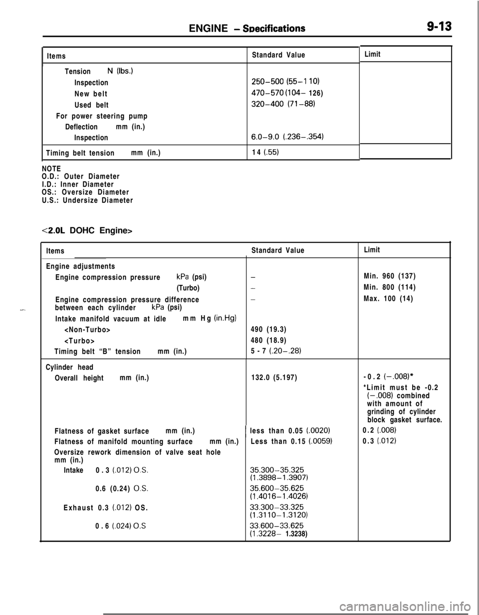
ENGINE - SDecificationsItems
TensionN (Ibs.)
Inspection
New belt
Used belt
For power steering pump
Deflectionmm (in.)
Inspection
Timing belt tensionmm (in.)Standard Value
250-500 (55-l 10)
470-570 (104- 126)
320-400 (71-88)
6.0-9.0 (.236-.354)14
(.55)NOTE
O.D.: Outer Diameter
I.D.: Inner Diameter
OS.: Oversize Diameter
U.S.: Undersize Diameter<2.0L DOHC Engine>
-ItemsStandard ValueLimit
Engine adjustments
Engine compression pressurekPa (psi)
(Turbo)
Engine compression pressure difference
between each cylinderkPa (psi)
Intake manifold vacuum at idlemm Hg
(in.Hg)
Timing belt “B” tensionmm (in.)
-
-
-490 (19.3)
480 (18.9)
5-7
(.20-.28)Cylinder head
Overall heightmm (in.)132.0 (5.197)
Flatness of gasket surfacemm (in.)
Flatness of manifold mounting surfacemm (in.)
Oversize rework dimension of valve seat hole
mm (in.)
Intake0.3
(.012) 0,s.0.6 (0.24)
0,s.Exhaust 0.3
(.012) OS.
0.6
(.024) 0.S~ less than 0.05
(.0020)Less than 0.15
(.0059)
35.300-35.325(1.3898-1.3907)
35.600-35.625
(1.4016-l .4026)
33.300-33.325(1.3110-1.3120)
33.600-33.625
(1.3228- 1.3238)Limit
Min. 960 (137)
Min. 800 (114)
Max. 100 (14)
-0.2
(-,008)”*Limit must be -0.2
(- .008) combined
with amount of
grinding of cylinder
block gasket surface.
0.2
(.008)0.3
(.012)
Page 821 of 1216
MANUAL TRANSAXLE
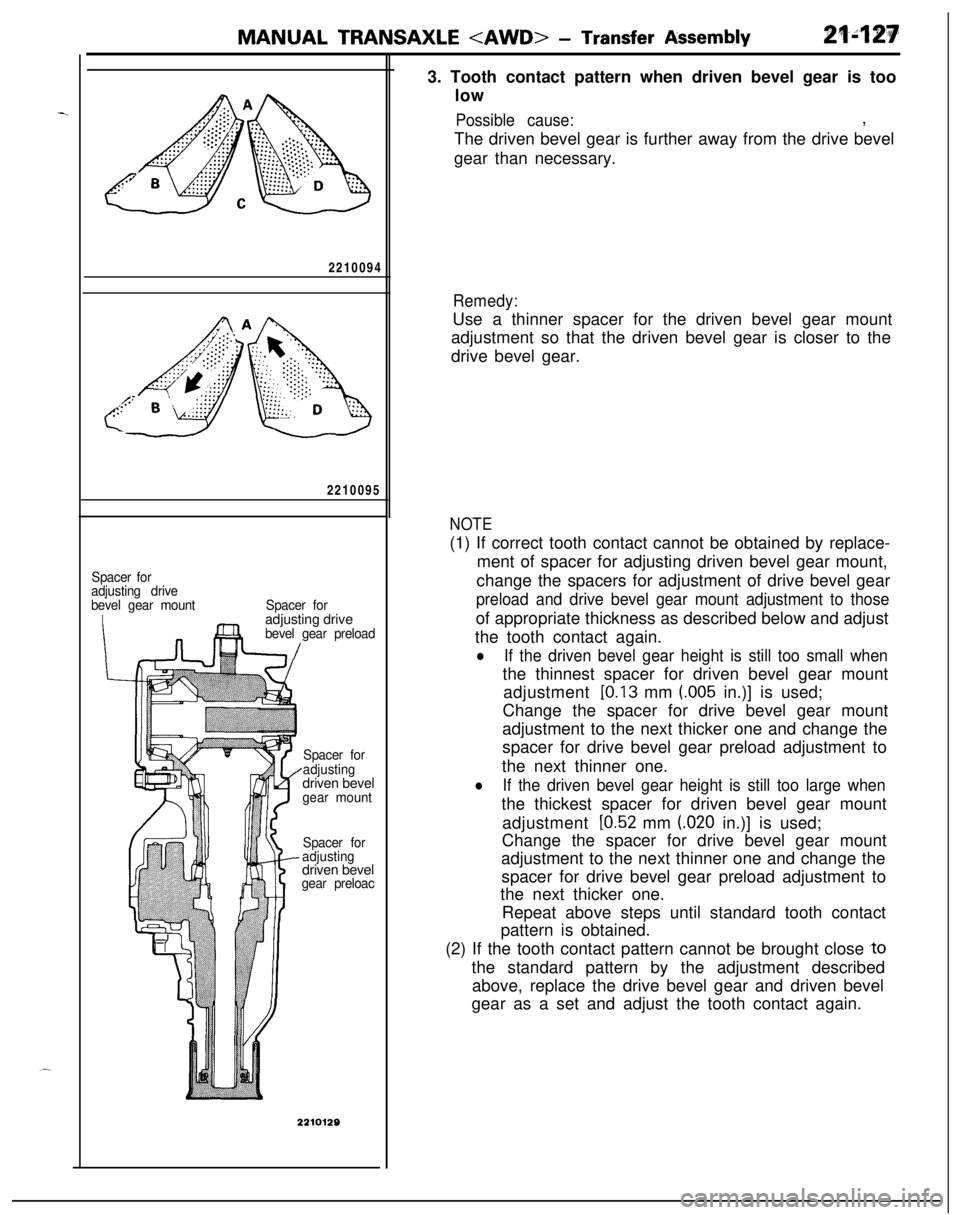
2210095
Spacer for
adjusting drive
bevel gear mount
ISpacer foradjusting drive
bevel gear preload
Spacer for
adjustingdriven bevel
gear mount
Spacer for
adjustingdriven bevel
gear preloac3. Tooth contact pattern when driven bevel gear is too
low
Possible cause:,
The driven bevel gear is further away from the drive bevel
gear than necessary.
Remedy:Use a thinner spacer for the driven bevel gear mount
adjustment so that the driven bevel gear is closer to the
drive bevel gear.
NOTE(1) If correct tooth contact cannot be obtained by replace-
ment of spacer for adjusting driven bevel gear mount,
change the spacers for adjustment of drive bevel gear
preload and drive bevel gear mount adjustment to thoseof appropriate thickness as described below and adjust
the tooth contact again.
lIf the driven bevel gear height is still too small whenthe thinnest spacer for driven bevel gear mount
adjustment
[0.13 mm (.005 in.)] is used;
Change the spacer for drive bevel gear mount
adjustment to the next thicker one and change the
spacer for drive bevel gear preload adjustment to
the next thinner one.
lIf the driven bevel gear height is still too large whenthe thickest spacer for driven bevel gear mount
adjustment
[0.52 mm (020 in.)] is used;
Change the spacer for drive bevel gear mount
adjustment to the next thinner one and change the
spacer for drive bevel gear preload adjustment to
the next thicker one.
Repeat above steps until standard tooth contact
pattern is obtained.
(2) If the tooth contact pattern cannot be brought close
,tothe standard pattern by the adjustment described
above, replace the drive bevel gear and driven bevel
gear as a set and adjust the tooth contact again.