low beam MITSUBISHI ECLIPSE 1991 Service Manual
[x] Cancel search | Manufacturer: MITSUBISHI, Model Year: 1991, Model line: ECLIPSE, Model: MITSUBISHI ECLIPSE 1991Pages: 1216, PDF Size: 67.42 MB
Page 554 of 1216
14-100 FUEL SYSTEM- Fuel Pump, Fuel Gauge Unit and Overfill Limiter (Two-Way Valve) 4WD>SERVICE POINTS OF REMOVAL
NI4tmM2. DISCONNECTION OF HIGH PRESSURE FUEL HOSE
Refer to
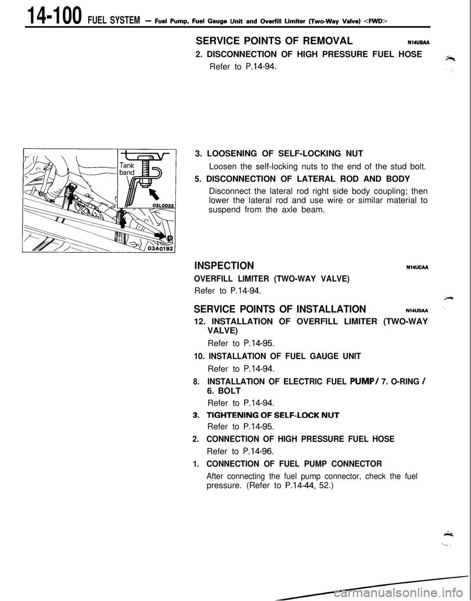
P.14-94.3. LOOSENING OF SELF-LOCKING NUT
Loosen the self-locking nuts to the end of the stud bolt.
5. DISCONNECTION OF LATERAL ROD AND BODY
Disconnect the lateral rod right side body coupling; then
lower the lateral rod and use wire or similar material to
suspend from the axle beam.
INSPECTION
OVERFILL LIMITER (TWO-WAY VALVE)Refer to
P.14-94.
N14UcM
SERVICE POINTS OF INSTALLATIONN14UDAA12. INSTALLATION OF OVERFILL LIMITER (TWO-WAY
VALVE)
Refer to
P.14-95.
10. INSTALLATION OF FUEL GAUGE UNITRefer to
P.14-94.
8.INSTALLATION OF ELECTRIC FUEL PUMP/ 7. O-RING /6. BOLT
Refer to
P.14-94.
3.TIGHTENING OF SELF-LOCK NUTRefer to
P.14-95.
2.CONNECTION OF HIGH PRESSURE FUEL HOSERefer to
P.14-96.
1.CONNECTION OF FUEL PUMP CONNECTOR
After connecting the fuel pump connector, check the fuelpressure. (Refer to P.1444, 52.)
Page 612 of 1216
17-2REAR SUSPENSION
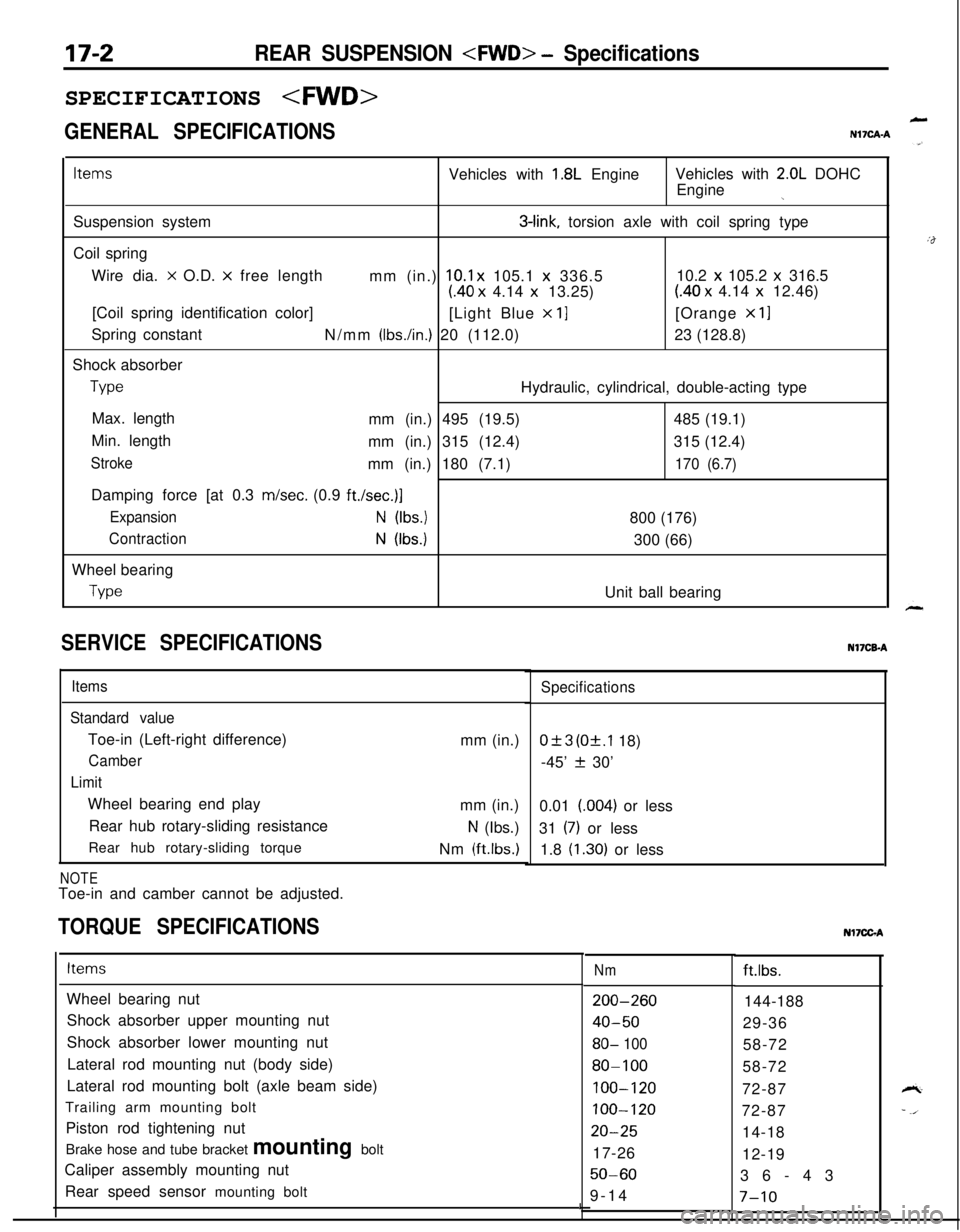
GENERAL SPECIFICATIONS
LN17CAA
ItemsVehicles with 1.8L EngineVehicles with 2.0L DOHC
Engine
jSuspension system
3-link, torsion axle with coil spring type
Coil spring
Wire dia.
x O.D. x free length
mm (in.) 10.1 x 105.1 x 336.510.2 x 105.2 x 316.5
(40 x 4.14 x 13.25)(40 x 4.14 x 12.46)
[Coil spring identification color]
[Light Blue
x 11[Orange x 11Spring constant
N/mm
(Ibs./in.) 20 (112.0)23 (128.8)
Shock absorber
TypeHydraulic, cylindrical, double-acting type
Max. length
mm (in.) 495 (19.5)485 (19.1)
Min. length
mm (in.) 315 (12.4)315 (12.4)
Strokemm (in.) 180 (7.1)170 (6.7)Damping force [at 0.3 m/set. (0.9
ft./set.)]
ExpansionN (Ibs.)800 (176)
ContractionN (Ibs.)300 (66)
Wheel bearing
TypeUnit ball bearing
SERVICE SPECIFICATIONS
Items
Standard valueToe-in (Left-right difference)
Camber
LimitWheel bearing end play
Rear hub rotary-sliding resistance
Rear hub rotary-sliding torque
NOTEToe-in and camber cannot be adjusted.mm (in.)
mm (in.)
N (Ibs.)
Nm
(ftlbs.)
TORQUE SPECIFICATIONS
Specifications
0+3 (Of.1 18)
-45’
f 30’
0.01 (004) or less
31
(7) or less
1.8
(1.30) or lessNI’ICB-A
ItemsNmft.lbs.
Wheel bearing nut
Shock absorber upper mounting nut
Shock absorber lower mounting nut
Lateral rod mounting nut (body side)
Lateral rod mounting bolt (axle beam side)
Trailing arm mounting bolt
Piston rod tightening nut
Brake hose and tube bracket mounting bolt
Caliper assembly mounting nut
Rear speed sensor mounting bolt
200-260
40-50
80- 100
80-100
100-120
100-120
20-2517-26
50-609-14144-188
29-36
58-72
58-72
72-87
72-87
14-18
12-19
36-43
I7-10
Nl7CGA
Page 616 of 1216
17-6REAR SUSPENSION
Drive out
BayArbor
Race
BearingSERVICE POINTS OF REMOVAL
Nl7QBh
1.REMOVAL OF REAR SPEED SENSOR
5-Wheel Speed Sensor.
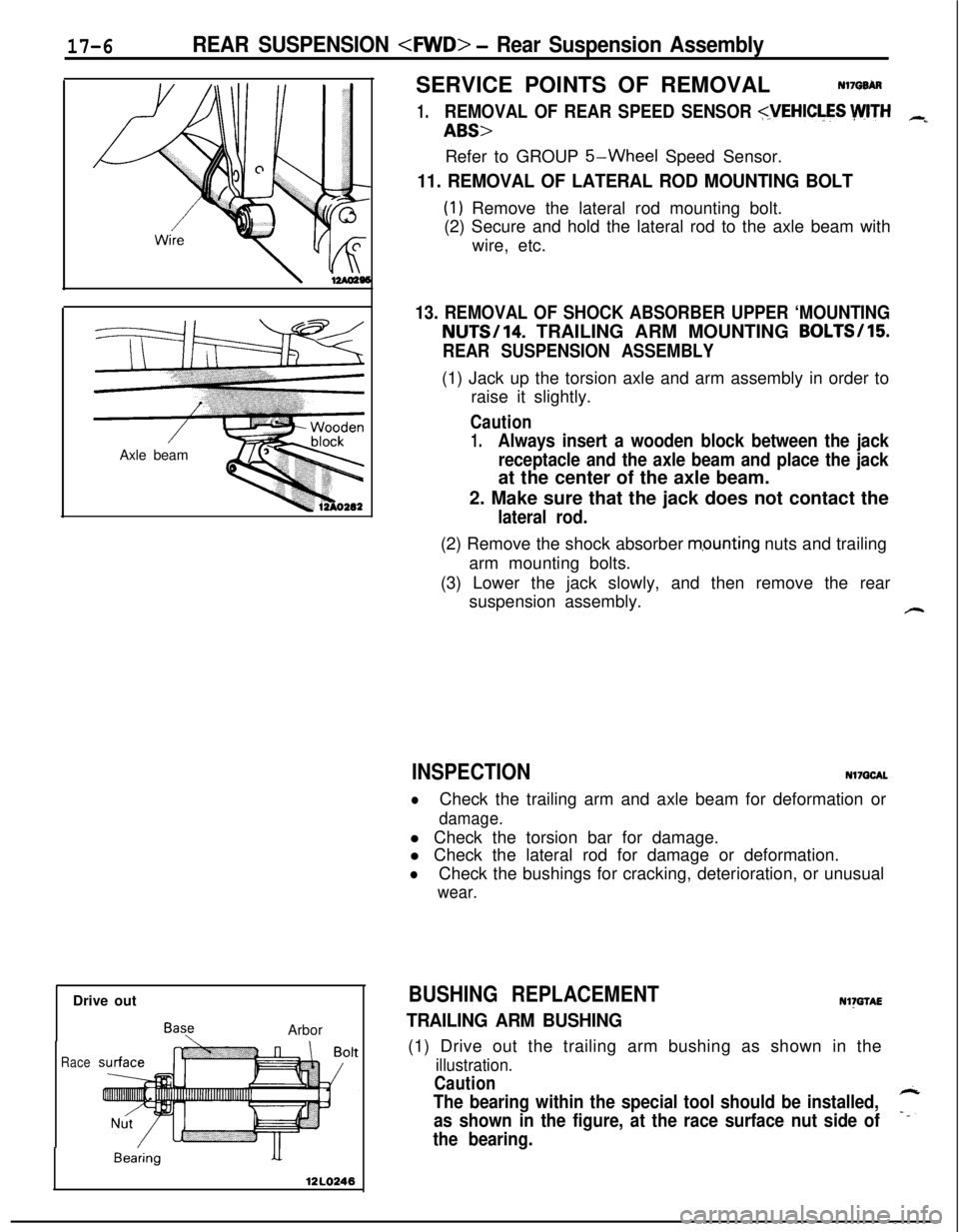
11. REMOVAL OF LATERAL ROD MOUNTING BOLT
(1) Remove the lateral rod mounting bolt.
(2) Secure and hold the lateral rod to the axle beam with
wire, etc.
13. REMOVAL OF SHOCK ABSORBER UPPER ‘MOUNTINGNUTS/14. TRAILING ARM MOUNTING BOLTS/15
REAR SUSPENSION ASSEMBLY(1) Jack up the torsion axle and arm assembly in order to
raise it slightly.
Caution
1.Always insert a wooden block between the jack
receptacle and the axle beam and place the jackat the center of the axle beam.
2. Make sure that the jack does not contact the
lateral rod.(2) Remove the shock absorber
m,ounting nuts and trailing
arm mounting bolts.
(3) Lower the jack slowly, and then remove the rear
suspension assembly.
#-
INSPECTIONNl7QCAL
lCheck the trailing arm and axle beam for deformation or
damage.l Check the torsion bar for damage.
l Check the lateral rod for damage or deformation.
lCheck the bushings for cracking, deterioration, or unusual
wear.
BUSHING REPLACEMENTNl)GTAE
TRAILING ARM BUSHING(1) Drive out the trailing arm bushing as shown in the
illustration.
Caution
The bearing within the special tool should be installed,
as shown in the figure, at the race surface nut side of7
the bearing.
Page 617 of 1216
-.REAR SUSPENSION
- Rear Suspension Assembly
Press in
BearingChamfered side
12l.0247CROSS SECT. A-A
Wheel, bearing
nut
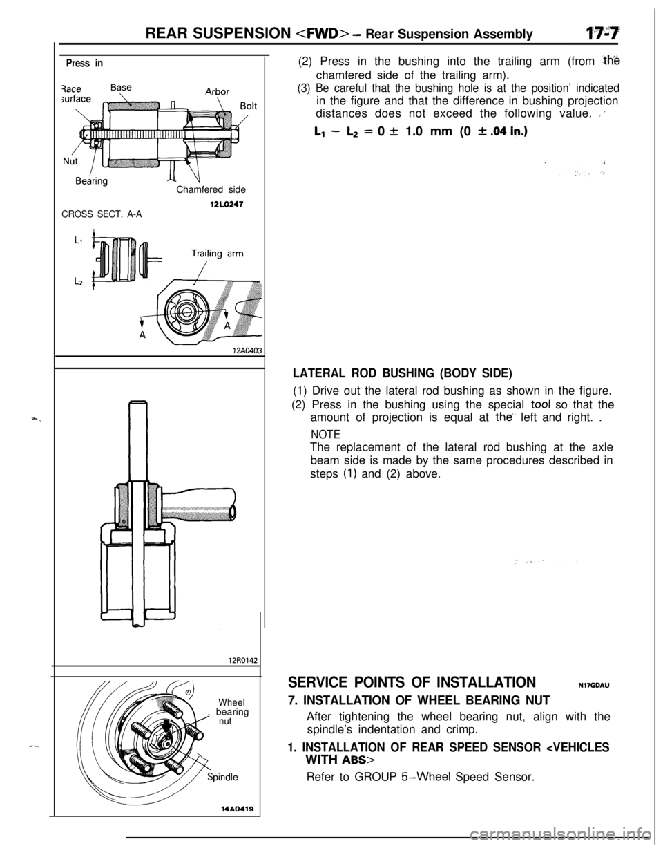
pindle(2) Press in the bushing into the trailing arm (from
ahechamfered side of the trailing arm).
(3) Be careful that the bushing hole is at the position’ indicatedin the figure and that the difference in bushing projection
distances does not exceed the following value.
: :
Ll -L2= 0 + 1.0 mm (0 * .04 in.)
LATERAL ROD BUSHING (BODY SIDE)(1) Drive out the lateral rod bushing as shown in the figure.
(2) Press in the bushing using the special tool so that the
amount of projection is equal at
the’, left and right. .
NOTEThe replacement of the lateral rod bushing at the axle
beam side is made by the same procedures described in
steps
(1) and (2) above.
SERVICE POINTS OF INSTALLATIONNI’IGDAU
7. INSTALLATION OF WHEEL BEARING NUTAfter tightening the wheel bearing nut, align with the
spindle’s indentation and crimp.
1. INSTALLATION OF REAR SPEED SENSOR
5-Wheel Speed Sensor.
Page 618 of 1216
17-8REAR SUSPENSION
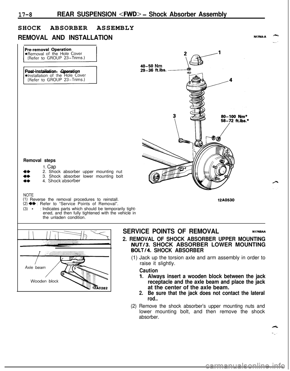
REMOVAL AND INSTALLATIONN17NA-A
Post-installation Operation
Removal steps
1. Cap
::2. Shock absorber upper mounting nut
3. Shock absorber lower mounting bolta*4. Shock.absorber
NOTE(I) Reverse the removal procedures to reinstall.(2) ** : Refer to “Service Points of Removal”.
(3) *: Indicates parts which should be temporarily tight-
ened, and then fully tightened with the vehicle in
the unladen condition.
40-50 Nm29-36 ft.lbs.
12A0530
SERVICE POINTS OF REMOVALNI’INBAA
2. REMOVAL OF SHOCK ABSORBER UPPER MOUNTINGNUT/3. SHOCK ABSORBER LOWER MOUNTING
BOLT/4. SHOCK ABSORBER(1) Jack up the torsion axle and arm assembly in order to
raise it slightly.
Caution
1.Always insert a wooden block between the jack
receptacle and the axle beam and place the jackat the center of the axle beam.
2.Be sure that the jack does not contact the lateral
rod..
(2) Remove the shock absorber’s upper mounting nuts andlower mounting bolt, and then remove the shock
absorber.
Page 622 of 1216
17-12REAR SUSPENSION
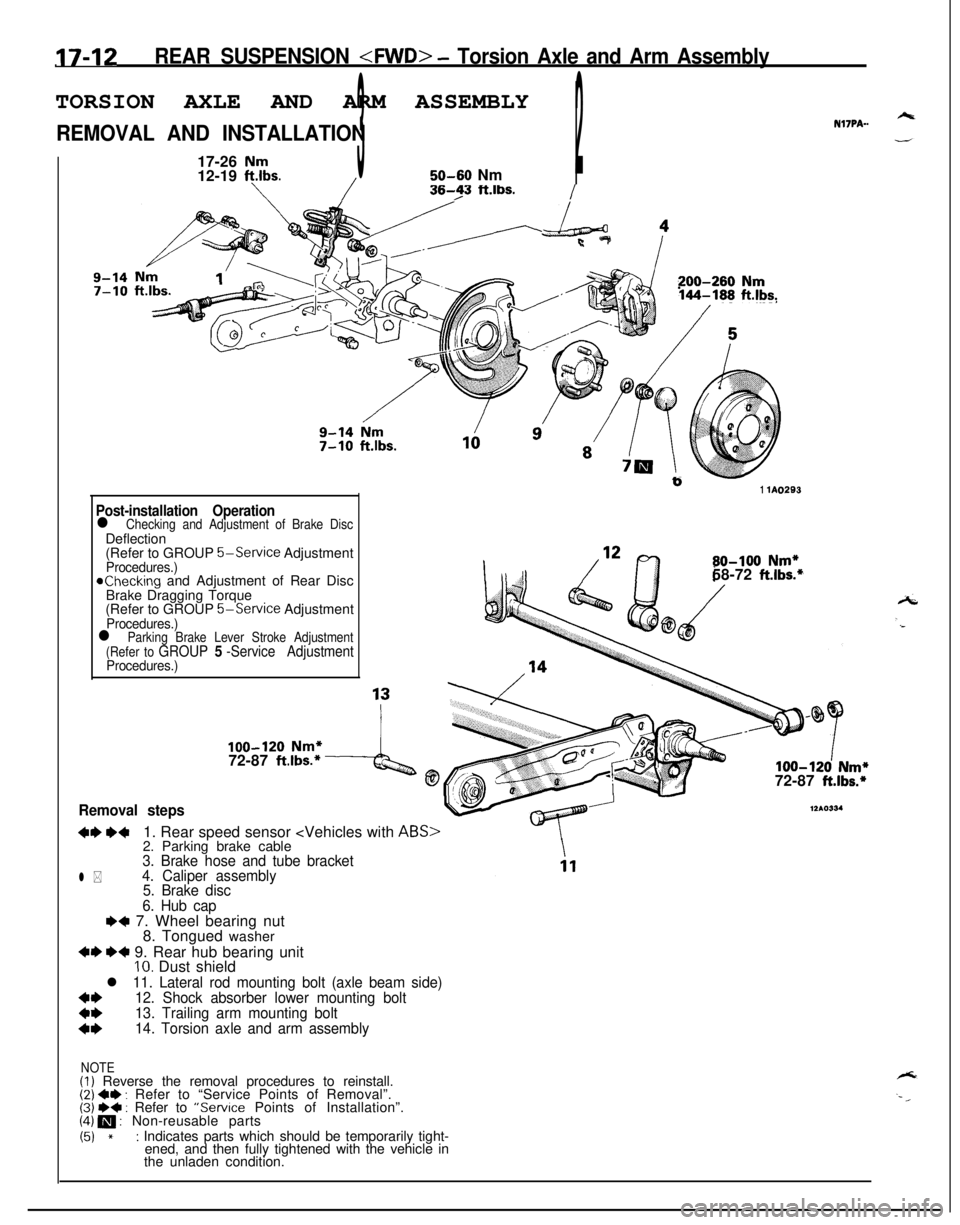
REMOVAL AND INSTALLATIONNl’IPA-.
17-26
Nm12-19 ft.lbs.350-60 Nm2/I
/36-23 ft.lbs./
Nm1’200-260 Nm144-188 ft.lbs.
b1 lA0293
Post-installation Operationl Checking and Adjustment of Brake DiscDeflection
(Refer to GROUP
5-Service AdjustmentProcedures.)achecking and Adjustment of Rear Disc
Brake Dragging Torque
(Refer to GROUP
5-Service AdjustmentProcedures.)
80-100 Nm*58-72 ft.lbs.*
l Parking Brake Lever Stroke Adjustment
(Refer to GROUP 5 -Service AdjustmentProcedures.)
100-120 Nm*72-87 ft.lbs.*4@100-120 Nm*72-87 ft.lbs.*
Removal steps
+I) ++1. Rear speed sensor
12*0334
l *
3. Brake hose and tube bracket
4. Caliper assembly
5. Brake disc
6. Hub cap
e+ 7. Wheel bearing nut
8. Tongued washer
+I) *+ 9. Rear hub bearing unitIO. Dust shield
l 11. Lateral rod mounting bolt (axle beam side)
*I)12. Shock absorber lower mounting bolt
13. Trailing arm mounting bolt
14. Torsion axle and arm assembly
NOTE(I) Reverse the removal procedures to reinstall.(2) ~~ : Refer to “Service Points of Removal”.(3j W+ : Refer to “Service Points of Installation”.(4) m : Non-reusable parts
(51 *: Indicates parts which should be temporarily tight-
ened, and then fully tightened with the vehicle in
the unladen condition.
Page 623 of 1216
REAR SUSPENSION
Inut
-
-Spindle
14AO419
SERVICE POINTS OF REMOVALNliP9AG
1.REMOVAL OF REAR SPEED SENSOR
5-Wheel Speed Sensor.
4. REMOVAL OF CALIPER ASSEMBLYRemove the caliper assembly and suspend it with a piece
of wire.
9. REMOVAL OF REAR HUB BEARING UNIT
NOTERear hub bearing unit cannot be disassemble.
12. REMOVAL OF SHOCK ABSORBER LOWER MOUNTING
BOLT/lB. TRAILING ARM MOUNTING BOLT/ 14.
TORSION AXLE AND ARM ASSEMBLY
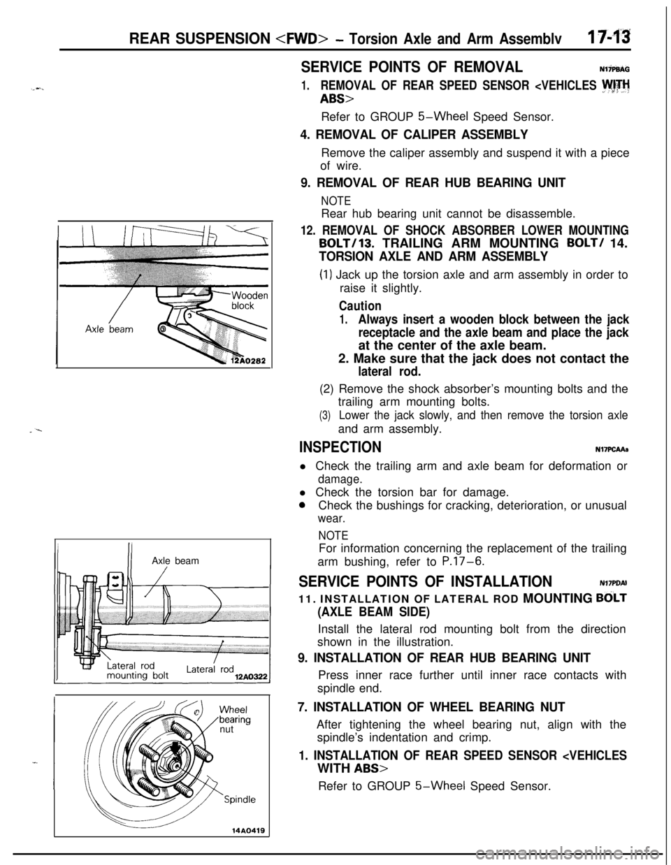
(1) Jack up the torsion axle and arm assembly in order to
raise it slightly.
Caution
1.Always insert a wooden block between the jack
receptacle and the axle beam and place the jackat the center of the axle beam.
2. Make sure that the jack does not contact the
lateral rod.(2) Remove the shock absorber’s mounting bolts and the
trailing arm mounting bolts.
(3)Lower the jack slowly, and then remove the torsion axleand arm assembly.
INSPECTIONN17PCAAa
l Check the trailing arm and axle beam for deformation or
damage.l Check the torsion bar for damage.
0Check the bushings for cracking, deterioration, or unusual
wear.
NOTEFor information concerning the replacement of the trailing
arm bushing, refer to
P.17-6.
SERVICE POINTS OF INSTALLATIONN17PDAI
11. INSTALLATION OF LATERAL ROD MOUNTING
BdLT
(AXLE BEAM SIDE)Install the lateral rod mounting bolt from the direction
shown in the illustration.
9. INSTALLATION OF REAR HUB BEARING UNITPress inner race further until inner race contacts with
spindle end.
7. INSTALLATION OF WHEEL BEARING NUTAfter tightening the wheel bearing nut, align with the
spindle’s indentation and crimp.
1. INSTALLATION OF REAR SPEED SENSOR
5-Wheel Speed Sensor.