remote control MITSUBISHI ECLIPSE 1991 Service Manual
[x] Cancel search | Manufacturer: MITSUBISHI, Model Year: 1991, Model line: ECLIPSE, Model: MITSUBISHI ECLIPSE 1991Pages: 1216, PDF Size: 67.42 MB
Page 1045 of 1216
23-lBODY
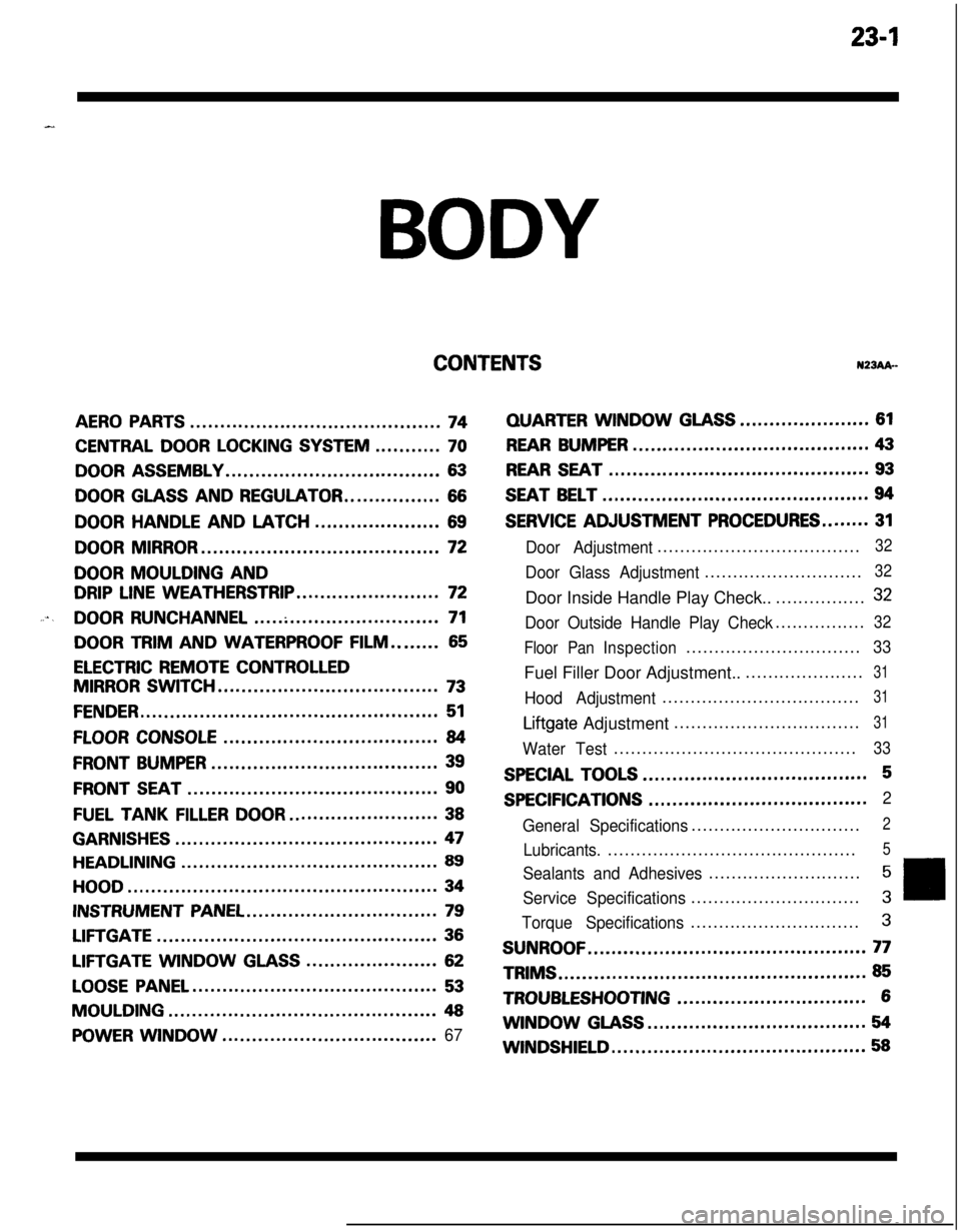
CONTENTSN23Ak-
AERO PARTS..........................................74
CENTRAL DOOR LOCKING SYSTEM...........70
DOOR ASSEMBLY....................................63
DOOR GLASS AND REGULATOR................66
DOORHANDLEANDLATCH.....................69
DOOR MIRROR........................................72
DOOR MOULDING AND
DRIP LINE WEATHERSTRIP........................72
....DOOR RUNCHANNEL...............................71
DOOR TRIM AND WATERPROOF FILM........65
ELECTRIC REMOTE CONTROLLED
MIRROR SWITCH.....................................73
FENDER..................................................51
FLOOR CONSOLE....................................84
FRONT BUMPER......................................39
FRONT SEAT..........................................90
FUEL TANKFILLERDOOR.........................38
GARNISHES............................................47
HEADLINING...........................................89
HOOD....................................................34
INSTRUMENT PANEL................................79
LIFTGATE...............................................36
LIFTGATE WINDOWGLASS......................62
LOOSE PANEL.........................................53
MOULDING.............................................48
POWER WINDOW....................................67
QUARTERWINDOWGLASS......................61
REAR BUMPER........................................43
REAR SEAT............................................93
SEAT BELT.............................................94
SERVICE ADJUSTMENT PROCEDURES........31
Door Adjustment....................................32
Door Glass Adjustment............................32Door Inside Handle Play Check..................
32
Door Outside Handle Play Check................32
Floor PanInspection...............................
33Fuel Filler Door Adjustment.......................
31
Hood Adjustment...................................31
Liftgate Adjustment.................................31
Water Test...........................................33
SPECIAL TOOLS......................................5
SPECIFICATIONS.....................................2
General Specifications..............................
2
Lubricants.............................................5
Sealants and Adhesives...........................5
Service Specifications..............................3
Torque Specifications..............................3
SUNROOF...............................................77TRIMS
....................................................85
TROUBLESHOOTING................................6WINDOW
GLASS.....................................54
WINDSHIELD...........................................58
Page 1047 of 1216
BODY - Specifications23-3
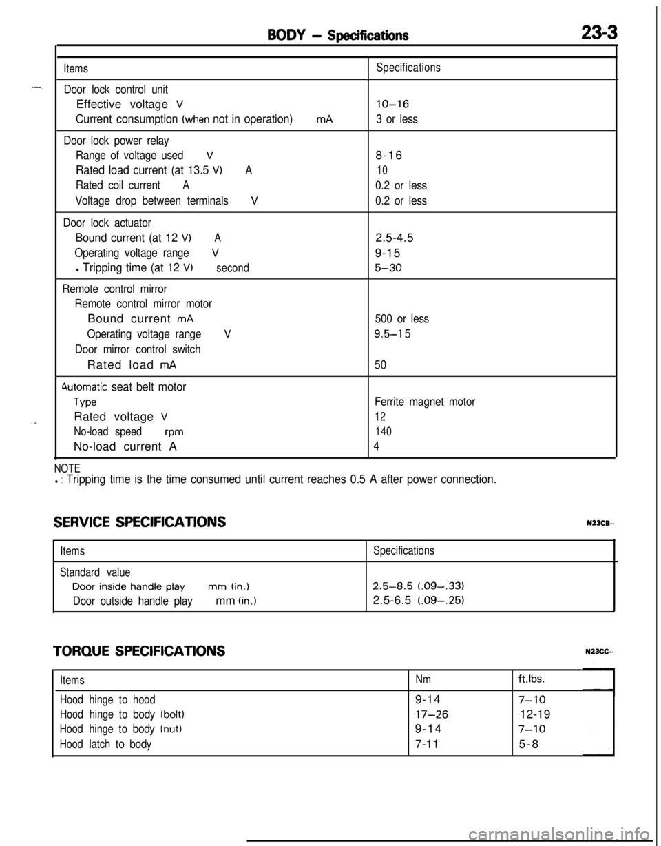
Items
Door lock control unitEffective voltage
V
Current consumption (when not in operation)
Door lock power relay
Range of voltage used
V
Rated load current (at 13.5 VIA
Rated coil currentA
Voltage drop between terminalsV
Door lock actuator
Bound current (at 12 VIA
Operating voltage rangeV
l Tripping time (at 12 V)second
Remote control mirror
Remote control mirror motorBound current
mA
Operating voltage range
V
Door mirror control switchRated load
mA
4utomatic seat belt motor
TypeRated voltage
V
No-load speedwmNo-load current A
mASpecifications
lo-16
3 or less8-16
10
0.2 or less
0.2 or less2.5-4.5
9-15
5-30
500 or less
9.5-l 5
50
Ferrite magnet motor
12
140
4
NOTEl : Tripping time is the time consumed until current reaches 0.5 A after power connection.
SERVICE SPECIFICATIONSN23CB--
ItemsSpecifications
Standard valueDoor
inside handle playmm (in.)2.5-8.5 (.09-,331
Door outside handle playmm (in.)2.5-6.5 (.09-.25)
TORQUE SPECIFICATIONS
ItemsNmft.lbs.
Hoodhingetohood9-14
7-10
Hoodhingetobody(bolt)17-2612-19
Hoodhingetobody(nut)9-147-10
Hoodlatchtobody7-115-8
Page 1058 of 1216
23-14BODY - Troubleshooting
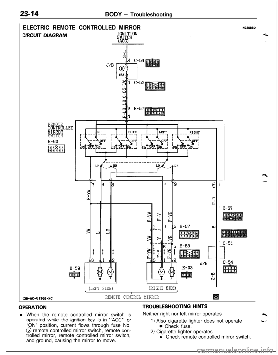
ELECTRIC REMOTE CONTROLLED MIRROR
CIRCUIT DIAGRAM
REMOTE&;;NT;LLED
SWITCH
MS-AC-UlSW-NC
L\/\I7
F
cl,,C
F
#
E-59
IpJJ%J
\/
3‘9g
4t
5
IL
;,,5 E-57m.--
!3
E-63
[z
J/BE-03
II
(LEFT SIDE)(RIGHT SIDE)LJt
REMOTE CONTROL MIRROR
1
-
i'
E-57
N23EBBD
OPERATIONl When the remote controlled mirror switch is
operated while the ignition key is in “ACC” or“ON” position, current flows through fuse No.@ remote controlled mirror switch, remote
con-trolled mirror, remote controlled mirror switch,
and ground, causing the mirror to move.
TROUBLESHOOTING HINTSNeither right nor left mirror operates
1) Also cigarette lighter does not operate0 Check fuse.
2) Cigarette lighter operates
l Check remote controlled mirror switch.
Page 1109 of 1216
BODY - Door Trim and Waterproof Film2345
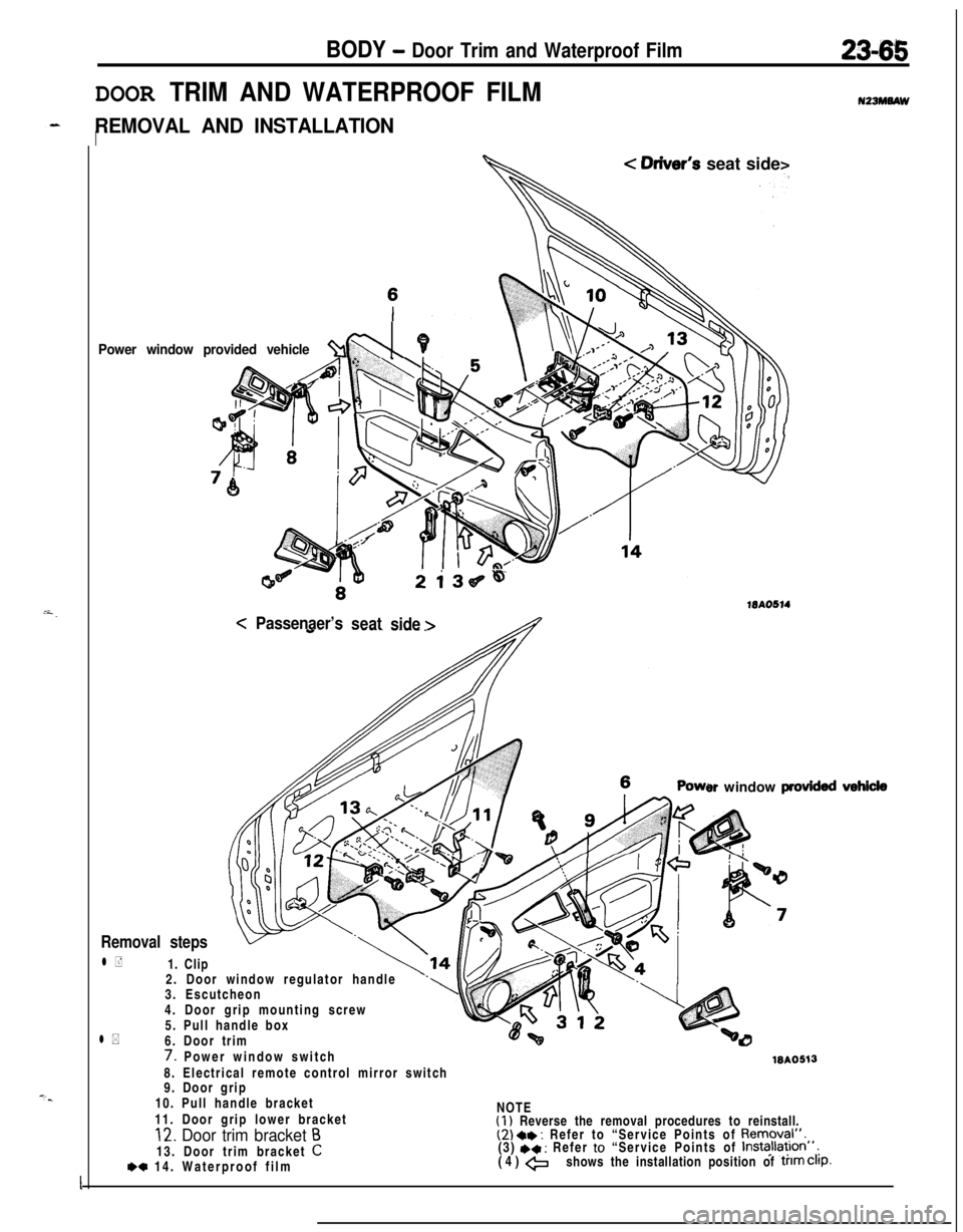
DOOR TRIM AND WATERPROOF FILM
REMOVAL AND INSTALLATIONI
Power window provided vehicle%l \PL
< Oriver’s seat side>
2i36~4
15AO514<
Passenaer’s
seat
side >
er window provkkd
Removal steps2. Door window regulator handle
3. Escutcheon
4. Door grip mounting screw
5. Pull handle box
l *6. Door trim
l +1. Clip
7. Power window switchWA05138. Electrical remote control mirror switch
9. Door grip
10. Pull handle bracket
11. Door grip lower bracketNOTE
(1) Reverse the removal procedures to reinstall.12. Door trim bracket B(2) a* : Refer to “Service Points of Removal”.13. Door trim bracket
C(3) +* : Refer to “Service Points of Installa~lon”,
*c 14. Waterproof film(4) +shows the installation position of trim Clip.
I
Page 1116 of 1216
23-72BODY -Door Moulding and Drip Line Weatherstrip/Door Mirror
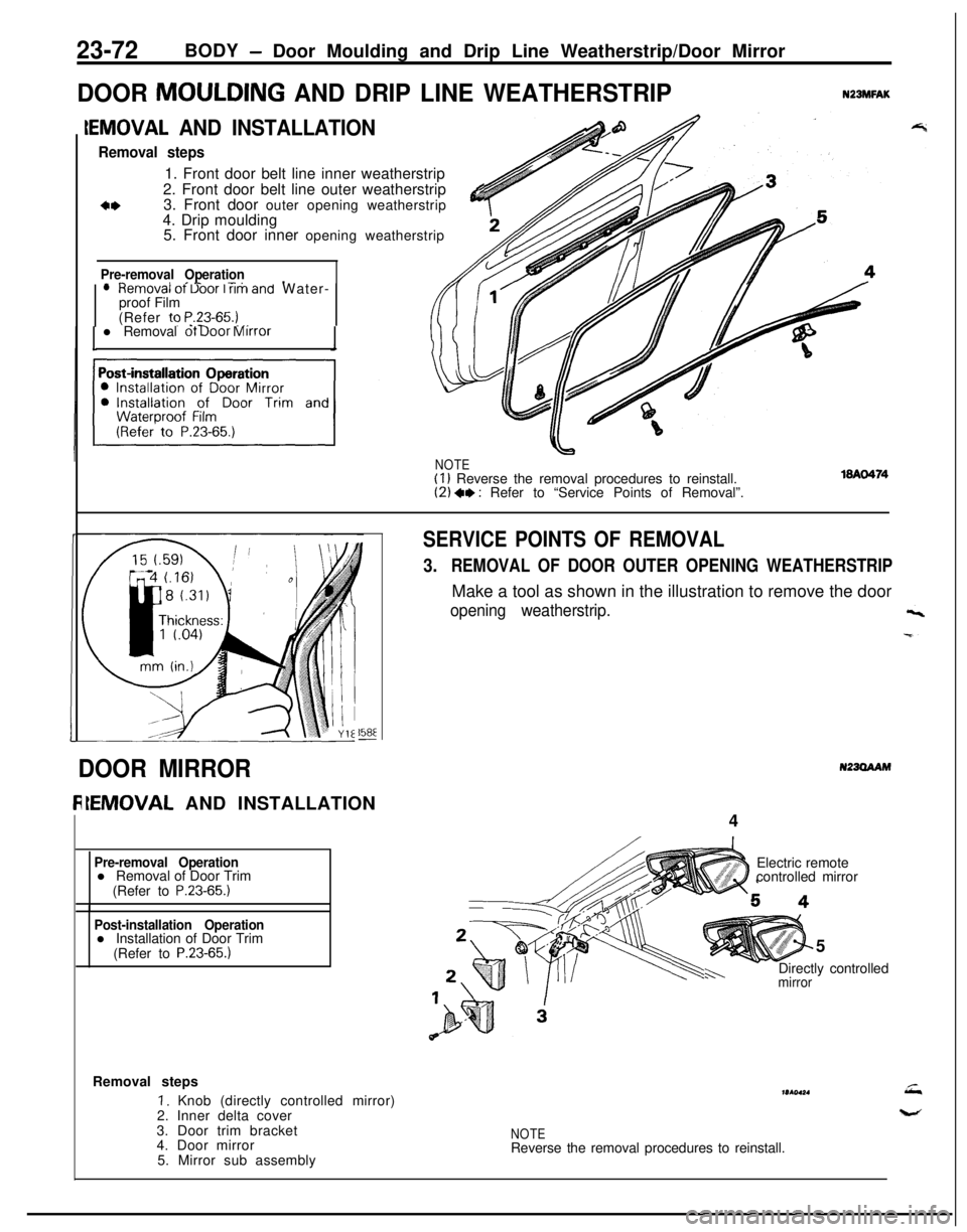
DOOR MOULDING AND DRIP LINE WEATHERSTRIPNZBMFAK
IEMOVAL AND INSTALLATION
Removal steps1. Front door belt line inner weatherstrip
2. Front door belt line outer weatherstrip
3. Front door outer opening weatherstrip
&4. Drip moulding
5. Front door inner opening weatherstrip
Pre-removal Operation- ^II_ -..lHemOVal ot Uoor I rim and Water-
proof Film
(Refer to
P.23-65.) _,. -l Removal ot Door Mirror
NOTE(I 1 Reverse the removal procedures to reinstall.(2) +, : Refer to “Service Points of Removal”.
158E-
SERVICE POINTS OF REMOVAL
3.REMOVAL OF DOOR OUTER OPENING WEATHERSTRIPMake a tool as shown in the illustration to remove the door
opening weatherstrip.
N23OAAMDOOR MIRROR
IEMOVAL AND INSTALLATION
4
Pre-removal Operationl Removal of Door Trim
(Refer to
P.23-65.)
Post-installation Operationl Installation of Door Trim
(Refer to
P.23-65.)5
mirrorh-.Directly controlled Electric remote
controlled mirror
Removal steps
I. Knob (directly controlled mirror)
2. Inner delta cover
3. Door trim bracket
4. Door mirror
5. Mirror sub assemblymr(ol*.
NOTEReverse the removal procedures to reinstall.
Page 1117 of 1216
BODY - Door Mirror/Electric Remote Controlled Mirror Switch23-73
18AO425
16P0109-
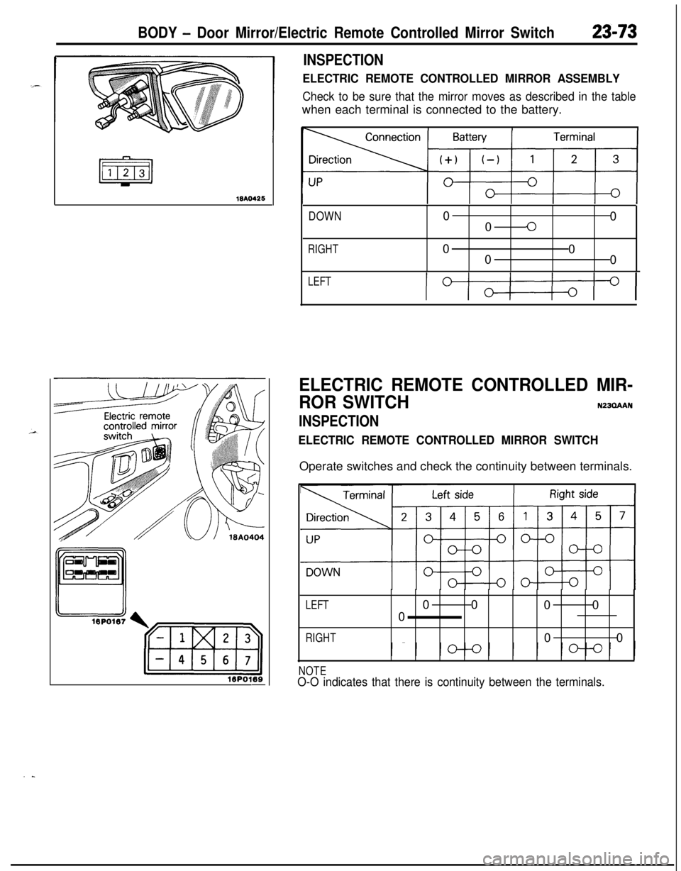
INSPECTION
ELECTRIC REMOTE CONTROLLED MIRROR ASSEMBLY
Check to be sure that the mirror moves as described in the tablewhen each terminal is connected to the battery.
DOWN0
0
00
RIGHT0
0
0
0
LEFT
IOI
ELECTRIC REMOTE CONTROLLED MIR-
ROR SWITCH
N23QAAN
INSPECTION
ELECTRIC REMOTE CONTROLLED MIRROR SWITCHOperate switches and check the continuity between terminals.
LEFT00
00
0
RIGHT00
NOTEO-O indicates that there is continuity between the terminals.
..