radio MITSUBISHI ECLIPSE 1991 Service Manual
[x] Cancel search | Manufacturer: MITSUBISHI, Model Year: 1991, Model line: ECLIPSE, Model: MITSUBISHI ECLIPSE 1991Pages: 1216, PDF Size: 67.42 MB
Page 18 of 1216

18INTRODUCTION AND MASTER TROUBLESHOOTING - Precautions b&ire Service
DOING SERVICE WORK IN GROUPS OF VO’bRMORE TECHNICIANS
.-I-7.IIf the service work is to be done by two or more technicians
working together, extra caution must be taken.
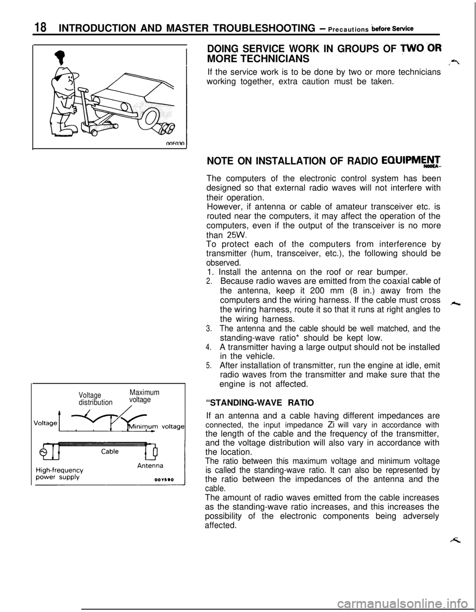
VoltagedistributionMaximum
voltage
NOTE ON INSTALLATION OF RADIO EQIJIPMEATeThe computers of the electronic control system has been
designed so that external radio waves will not interfere with
their operation.
However, if antenna or cable of amateur transceiver etc. is
routed near the computers, it may affect the operation of the
computers, even if the output of the transceiver is no more
than
25W.To protect each of the computers from interference by
transmitter (hum, transceiver, etc.), the following should be
observed.1. Install the antenna on the roof or rear bumper.
2.Because radio waves are emitted from the coaxial cable of
the antenna, keep it 200 mm (8 in.) away from the
computers and the wiring harness. If the cable must cross
hthe wiring harness, route it so that it runs at right angles to
the wiring harness.
3.The antenna and the cable should be well matched, and thestanding-wave ratio* should be kept low.
4.A transmitter having a large output should not be installed
in the vehicle.
5.After installation of transmitter, run the engine at idle, emit
radio waves from the transmitter and make sure that the
engine is not affected.
“STANDING-WAVE RATIO
If an antenna and a cable having different impedances are
connected, the input impedance Zi will vary in accordance with
the length of the cable and the frequency of the transmitter,
and the voltage distribution will also vary in accordance with
the location.
The ratio between this maximum voltage and minimum voltage
is called the standing-wave ratio. It can also be represented bythe ratio between the impedances of the antenna and the
cable.The amount of radio waves emitted from the cable increases
as the standing-wave ratio increases, and this increases the
possibility of the electronic components being adversely
affected.
Page 1124 of 1216

23-80BODY - Instrument Panel
REMOVAL AND INSTALLATION
-?7
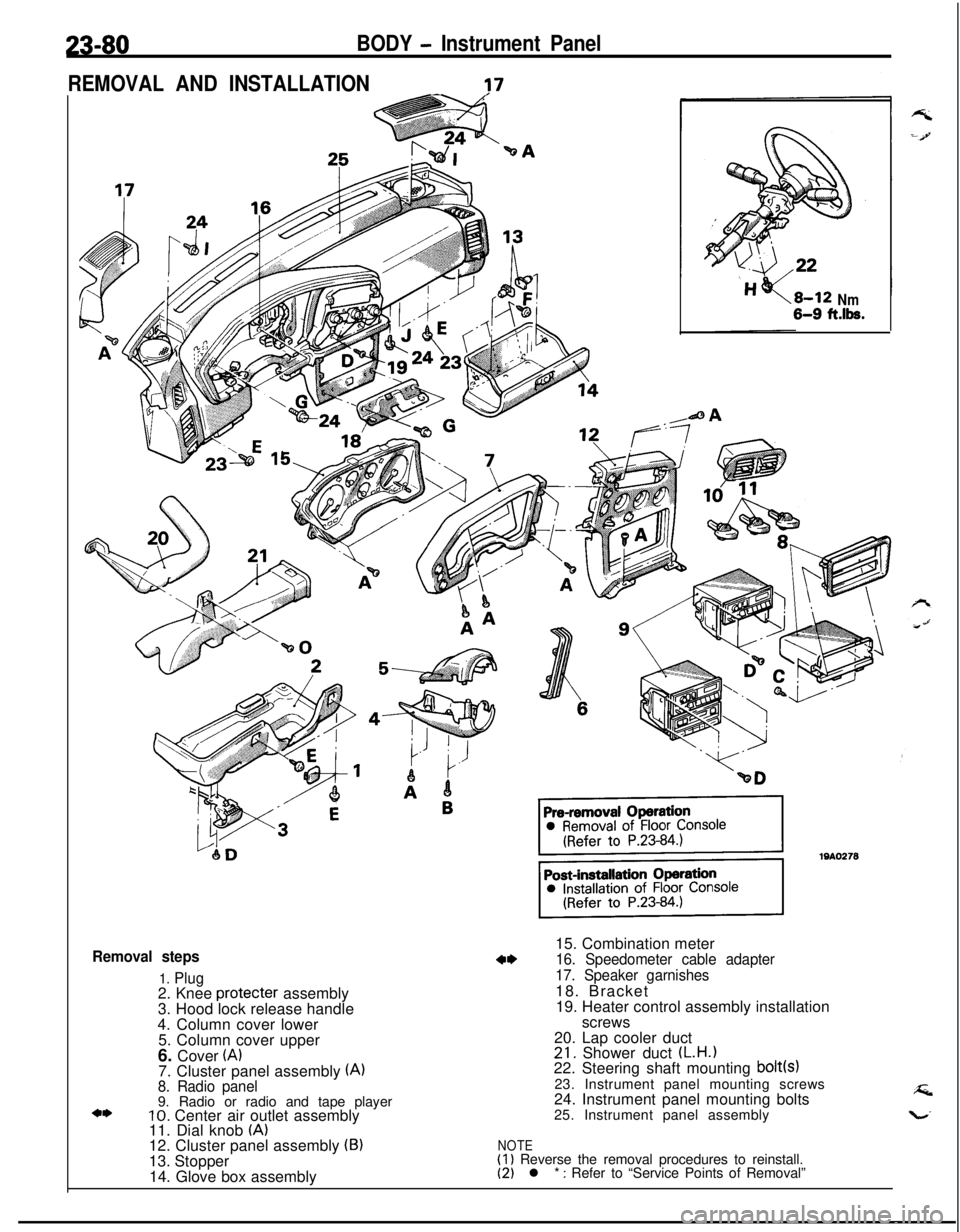
Removal steps
1. Plug2. Knee protecter assembly
3. Hood lock release handle
4. Column cover lower
5. Column cover upper
6. Cover
(A)7. Cluster panel assembly (A)8. Radio panel9. Radio or radio and tape player
10. Center air outlet assembly
11. Dial knob (A)12. Cluster panel assembly (B)13. Stopper
14. Glove box assembly
Nm6-9 ft.lk.15. Combination meter
16. Speedometer cable adapter
17. Speaker garnishes18. Bracket
19. Heater control assembly installation
screws
20. Lap cooler duct
21. Shower duct (L.H.122. Steering shaft mounting bolt(s)23. Instrument panel mounting screws
24. Instrument panel mounting bolts
25. Instrument panel assembly
NOTE(1) Reverse the removal procedures to reinstall.(2) l * : Refer to “Service Points of Removal”
Page 1170 of 1216

24-26HEATERS AND AIR CONDITIONING - Heater Control AssemblyHEATER CONTROL ASSEMBLY
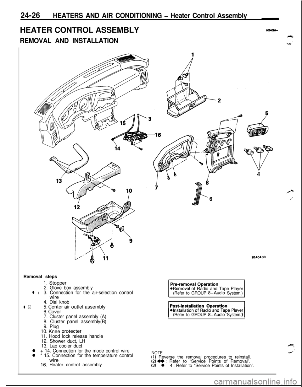
REMOVAL AND INSTALLATIONRemoval steps
1. Stopper2. Glove box assemblyl +3. Connection for the air-selection controlwire
4. Dial knob
l *;: CI.Z;Er air outlet assembly
7. Cluster panel assembly (A)
8. Cluster panel assembly(B)
9. Plug
10. Knee protecter11. Hood lock release handle
12. Shower duct, LH
13. Lap cooler duct
l + 14. Connection for the mode control wire
l * 15. Connection for the temperature controlwire
16. Heater control assembly4
6
2OAO430Pre-removal Operation
@Removal of Radio and Tape Player(Refer to GROUP 8-Audio System.)
(Refer to GROUP
8-Audio System.)
NOTE(1) Reverse the removal procedures to reinstall.(2) 4e : Refer to “Service Points of Removal”.(3) l 4 : Refer to “Service Points of Installation”.
Page 1174 of 1216

24-30HEATERS AND AIR CONDITIONING - Air Conditioner SwitchAIR CONDITIONER SWITCH
REMOVAL AND--N24OA..INSTALLATION
-2OAO419al Operationof
R;tdio and TanePlaver@Removal -..--._ _.-.-, -Removal steps
I. Air conditioner switch connectorCL7 Air rnnditinner switch
l Installation of Radio and Tape Player(Refer to GROUP 8-Audio System.)
NOTEOperation /Reverse
removal orocedures to reinstall.
I
77-. , .,a -.,a ,-,..-,.-. -.....,. ,.._._.__ _..- .-...-.-.r----- --
-----A
20A0427
20A0199
SERVICE POINTS OF REMOVALN24QBAF2. REMOVAL OF AIR CONDITIONER SWITCH
Remove the radio set, and insert hand to the back of the
cluster panel assembly through the produced opening.
Catching the air conditioner switch on the right and left
sides, push it toward you for removal.
INSPECTIONN24OCACaAIR CONDITIONER SWITCH CHECK
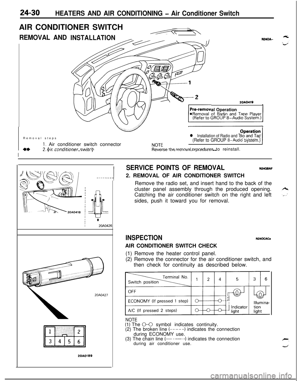
(1) Remove the heater control panel.
(2) Remove the connector for the air conditioner switch, and
then check for continuity as described below.
NOTE(1) The 0-0 symbol indicates continuity.
(2) The broken line (-----) indicates the connection
during ECONOMY use.
(3) The chain line
(- -----) indicates the connection
during air conditioner use.