service indicator MITSUBISHI ECLIPSE 1991 Service Manual
[x] Cancel search | Manufacturer: MITSUBISHI, Model Year: 1991, Model line: ECLIPSE, Model: MITSUBISHI ECLIPSE 1991Pages: 1216, PDF Size: 67.42 MB
Page 56 of 1216
2-8FRONT SUSPENSION - Service Adjustment Procedures
SERVICE ADJUSTMENT PROCEDURES
HUB END PLAY INSPECTIONNO2FAAB --- ’
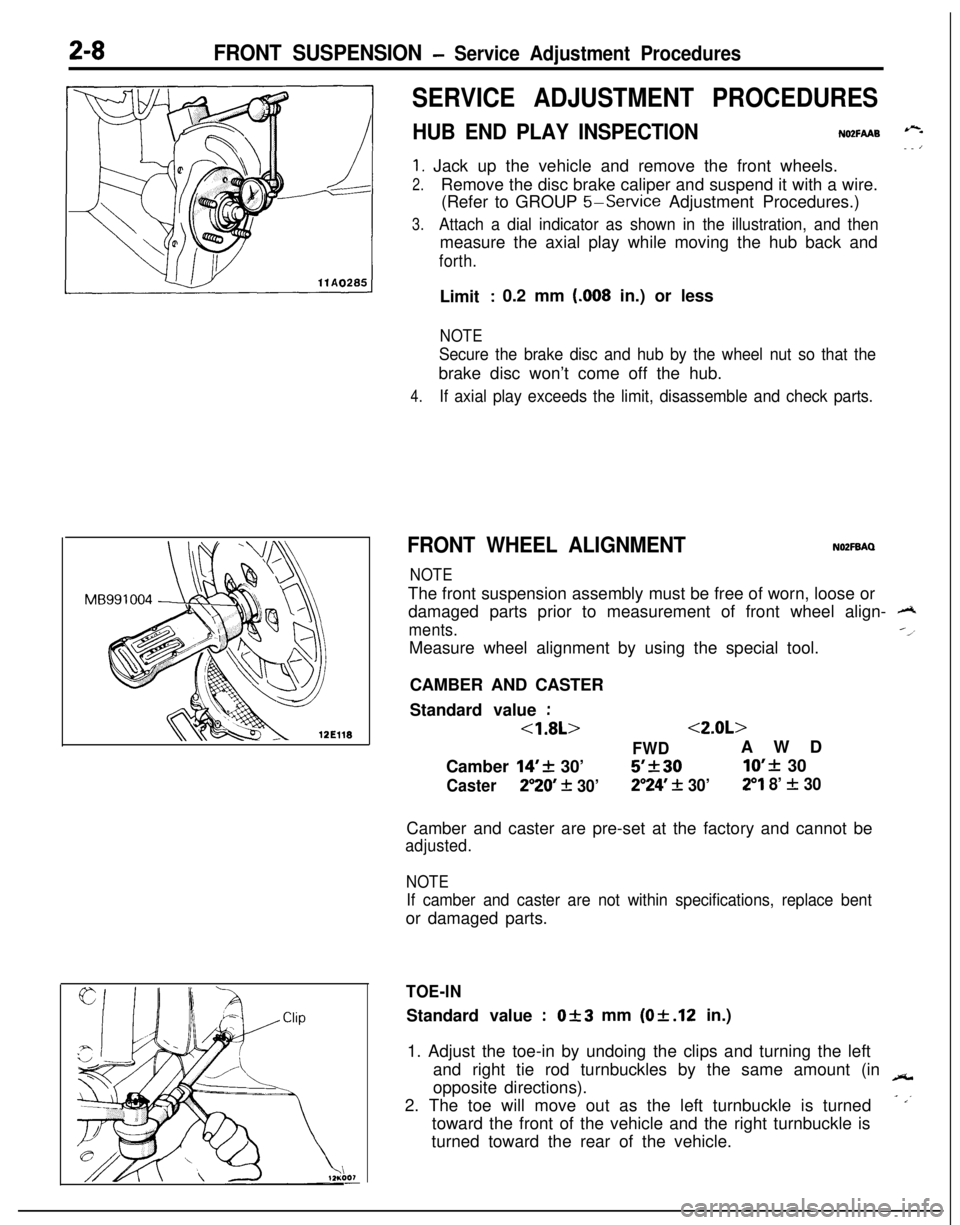
1. Jack up the vehicle and remove the front wheels.
2.Remove the disc brake caliper and suspend it with a wire.
(Refer to GROUP
5-Service Adjustment Procedures.)
3.Attach a dial indicator as shown in the illustration, and thenmeasure the axial play while moving the hub back and
forth.Limit
: 0.2 mm (.008 in.) or less
NOTE
Secure the brake disc and hub by the wheel nut so that thebrake disc won’t come off the hub.
4.If axial play exceeds the limit, disassemble and check parts.
FRONT WHEEL ALIGNMENTNOZFBAQ
NOTEThe front suspension assembly must be free of worn, loose or
damaged parts prior to measurement of front wheel align-
A
ments.--l
Measure wheel alignment by using the special tool.
CAMBER AND CASTER
Standard value
:
<1.8L><2.0L>
FWDAWD
Camber
14’+ 30’5’k3010’f 30
Caster250 + 30’2”24’ + 30’29 8’ f 30Camber and caster are pre-set at the factory and cannot be
adjusted.
NOTE
If camber and caster are not within specifications, replace bentor damaged parts.
TOE-INStandard value
:Of3 mm (Of.12 in.)
1. Adjust the toe-in by undoing the clips and turning the left
and right tie rod turnbuckles by the same amount (in
-opposite directions).
2. The toe will move out as the left turnbuckle is turned
- ,’toward the front of the vehicle and the right turnbuckle is
turned toward the rear of the vehicle.
Page 122 of 1216
3-20REAR AXLE - Differential CarrierMating marks
’
lODSO5
Beveled place
1 lA0274
SERVICE POINTS OF REMOVALN031BAL1. REMOVAL OF DRIVE SHAFT
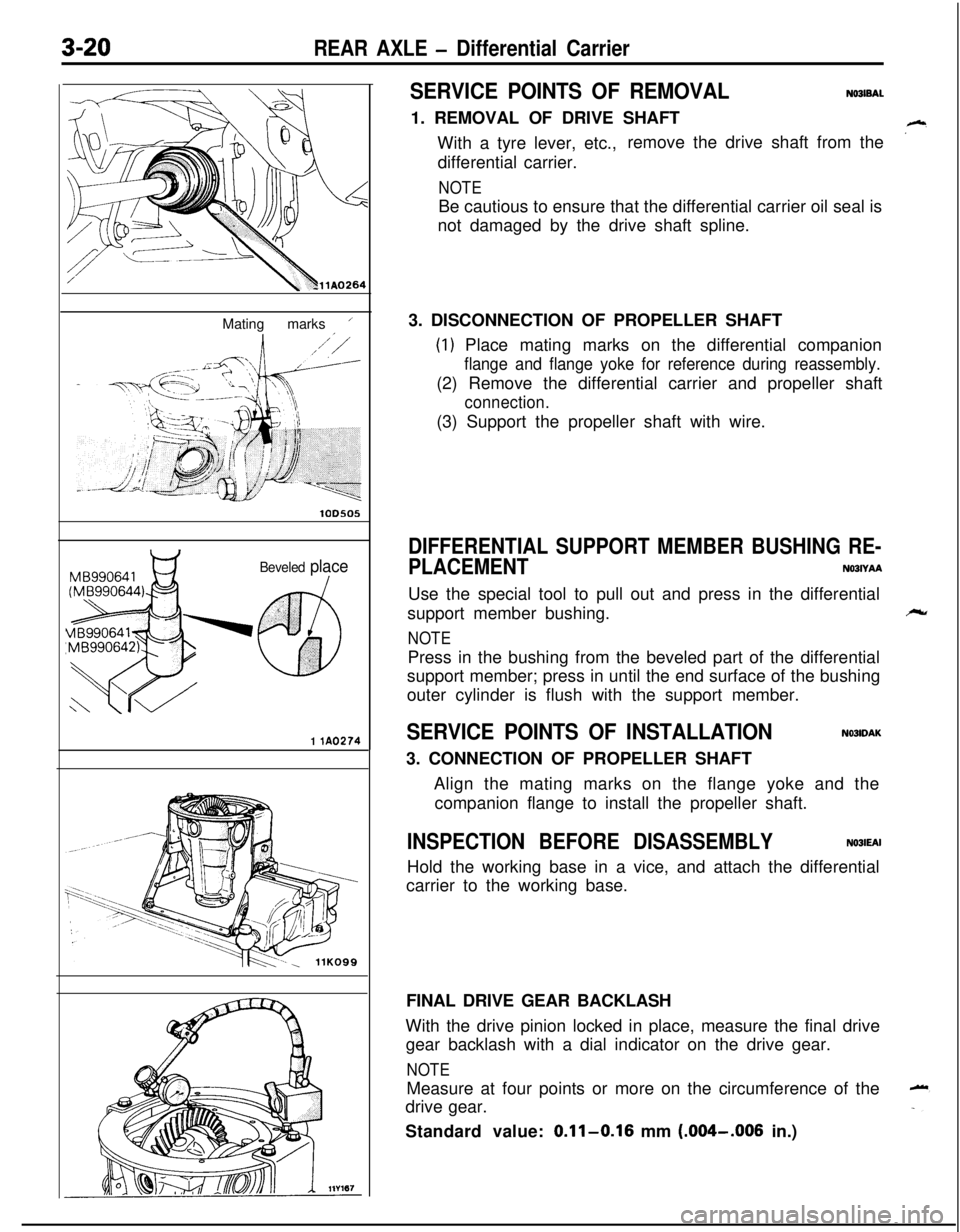
With a tyre lever, etc.,remove the drive shaft from the
differential carrier.
NOTEBe cautious to ensure that the differential carrier oil seal is
not damaged by the drive shaft spline.
3. DISCONNECTION OF PROPELLER SHAFT
(1) Place mating marks on the differential companion
flange and flange yoke for reference during reassembly.(2) Remove the differential carrier and propeller shaft
connection.(3) Support the propeller shaft with wire.
DIFFERENTIAL SUPPORT MEMBER BUSHING RE-
PLACEMENT
NOBIYAAUse the special tool to pull out and press in the differential
support member bushing.
NOTEPress in the bushing from the beveled part of the differential
support member; press in until the end surface of the bushing
outer cylinder is flush with the support member.
SERVICE POINTS OF INSTALLATIONN03lDAK3. CONNECTION OF PROPELLER SHAFT
Align the mating marks on the flange yoke and the
companion flange to install the propeller shaft.
INSPECTION BEFORE DISASSEMBLYNOJIEAIHold the working base in a vice, and attach the differential
carrier to the working base.
FINAL DRIVE GEAR BACKLASH
With the drive pinion locked in place, measure the final drive
gear backlash with a dial indicator on the drive gear.
NOTEMeasure at four points or more on the circumference of the
drive gear.
Standard value:
0.11-0.16 mm (.004-.006 in.)
Page 186 of 1216
5-46BRAKES - Service Adjustment ProceduresWhen new
When worn
14G0017
14LO169
14A0403
\14AO400
FRONT DISC BRAKE PAD CHECK AND REPLACE-
MENiNWFOAF
NOTE
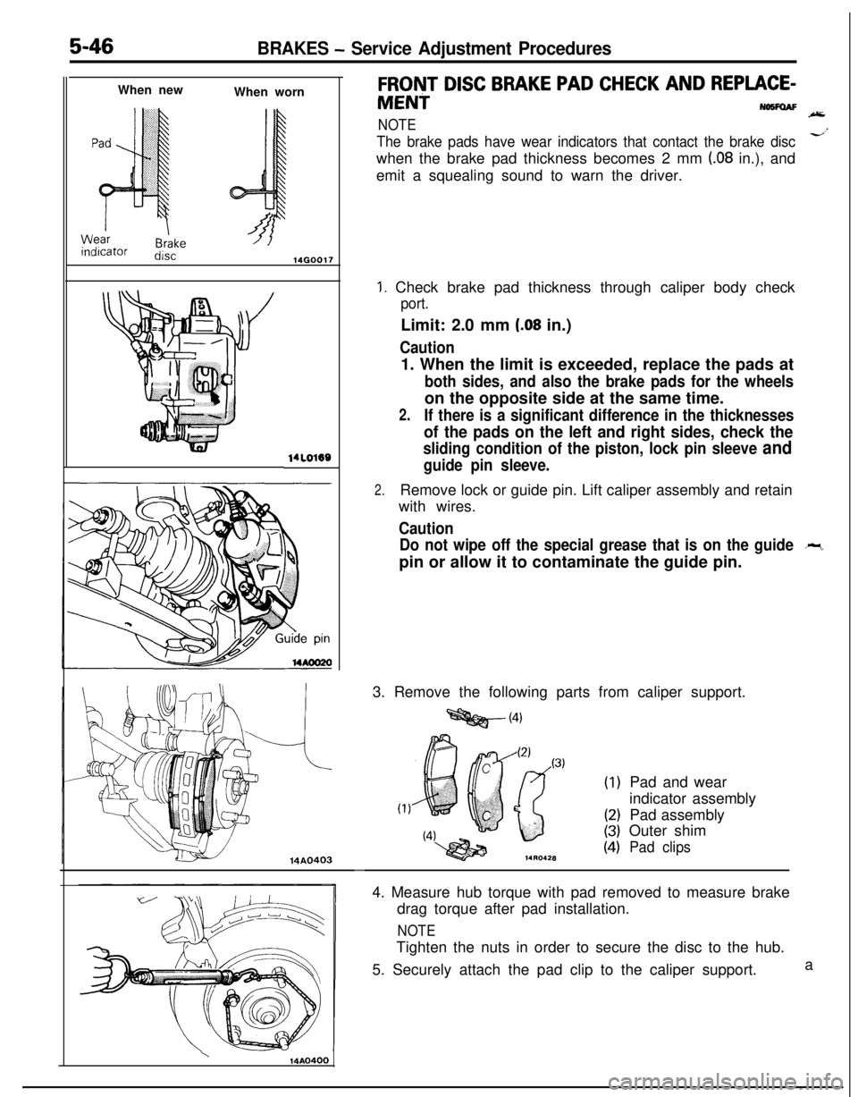
The brake pads have wear indicators that contact the brake discd’when the brake pad thickness becomes 2 mm
(.08 in.), and
emit a squealing sound to warn the driver.
1. Check brake pad thickness through caliper body check
port.Limit: 2.0 mm
(.08 in.)
Caution1. When the limit is exceeded, replace the pads at
both sides, and also the brake pads for the wheelson the opposite side at the same time.
2.If there is a significant difference in the thicknesses
of the pads on the left and right sides, check the
sliding condition of the piston, lock pin sleeve and
guide pin sleeve.
2.Remove lock or guide pin. Lift caliper assembly and retain
with wires.
Caution
Do not wipe off the special grease that is on the guide
-pin or allow it to contaminate the guide pin.
3. Remove the following parts from caliper support.
=Qg@-(4)
(1)
(2)
(3)
(4)Pad and wear
indicator assembly
Pad assembly
Outer shimPad clips
-4. Measure hub torque with pad removed to measure brake
drag torque after pad installation.
NOTETighten the nuts in order to secure the disc to the hub.
5. Securely attach the pad clip to the caliper support.a
Page 207 of 1216
BRAKES -Front Disc Brake5-67DISASSEMBLY AND REASSEMBLY
64-86
46-62
64-86
46-62
ft.lbs. ;
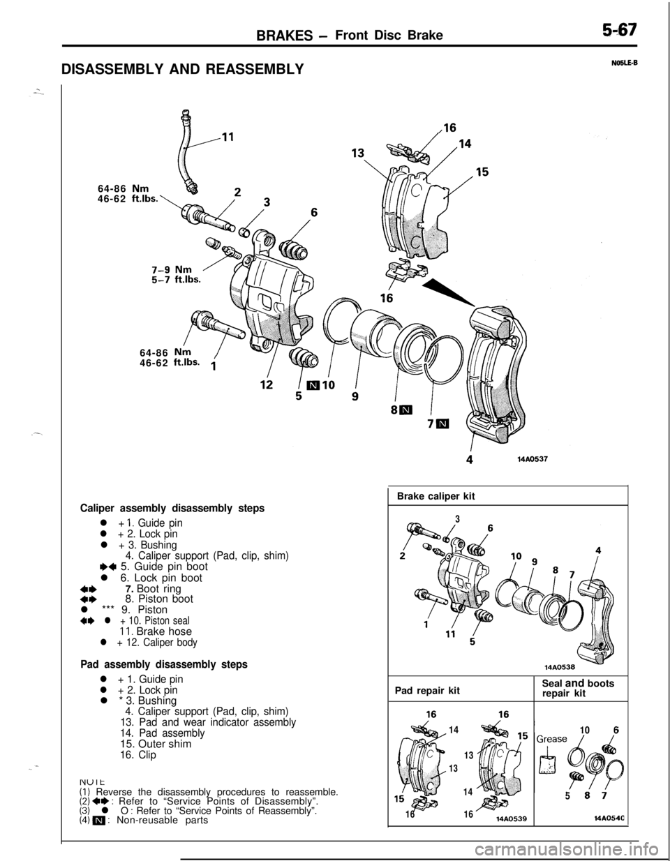
Caliper assembly disassembly steps
l + 1. Guide pin
l + 2. Lock pin
l + 3. Bushing
4. Caliper support (Pad, clip, shim)
e+ 5. Guide pin boot
l 6. Lock pin boot
::7. Boot ring
8. Piston boot
l *** 9. Piston
4I) l + 10. Piston sealIl. Brake hosel + 12. Caliper body
Pad assembly disassembly steps
l + 1. Guide pin
l + 2. Lock pinl * 3. Bushing
4. Caliper support (Pad, clip, shim)
13. Pad and wear indicator assembly
14. Pad assembly15. Outer shim
16. Clip
NOSLE-B
.16
(1) Reverse the disassembly procedures to reassemble.(2) +e : Refer to “Service Points of Disassembly”.(3) l O : Refer to “Service Points of Reassembly”.(4) m : Non-reusable partsBrake caliper kit
3Pad repair kitSeal and boots
repair kit
14
106
13
13
1614
1614AO539
514A054(3
Page 256 of 1216
7-8COOLING - Service Adjustment Procedures
04DooE
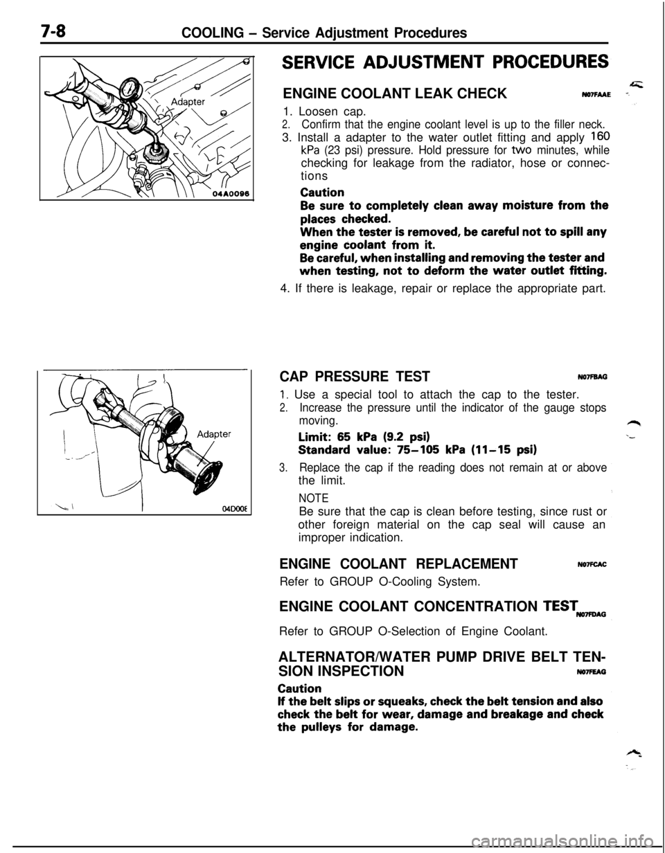
SERVICE ADJUSTMENT PROCEDURESENGINE COOLANT LEAK CHECK
NO7FAAE1. Loosen cap.
2.Confirm that the engine coolant level is up to the filler neck.3. Install a adapter to the water outlet fitting and apply
160
kPa (23 psi) pressure. Hold pressure for tvvo minutes, whilechecking for leakage from the radiator, hose or connec-
tionsCaution
Be sure to completely clean away moisture from the
places checked.When the tester
is removed, be careful not to spill anyengine coolant from
it.
Be careful, when installing and removing the tester andwhen testing, not
to deform the water outlet fitting.
4. If there is leakage, repair or replace the appropriate part.
CAP PRESSURE TESTNO’IFBAG
1. Use a special tool to attach the cap to the tester.
2.Increase the pressure until the indicator of the gauge stops
moving.Limit:
65 kPa (9.2 psi)Standard value:
75-105 kPa (11-15 psi)
3.Replace the cap if the reading does not remain at or abovethe limit.
NOTEBe sure that the cap is clean before testing, since rust or
other foreign material on the cap seal will cause an
improper indication.
ENGINE COOLANT REPLACEMENTRefer to GROUP O-Cooling System.NO’IFCACENGINE COOLANT CONCENTRATION
TESTmAGRefer to GROUP O-Selection of Engine Coolant.
ALTERNATOR/WATER PUMP DRIVE BELT TEN-
SION INSPECTION
NO7FEAGCaution
If the belt slips or squeaks, check the belt tension and also
check the belt for wear, damage and breakage and checkthe
pulleys for damage.
Page 455 of 1216
14-IFUEL SYSTEM
CONTENTS
AUTO-CRUISECONTROLSYSTEM...........................................109AUTO-CRUISECONTROL.......................................................140SERVICEADJUSTMENTPROCEDURES..............................135Accelerator Cable, Throttle Cable and Auto-cruise
ControlCableInspectionandAdjustment........................136Auto-cruise
ControlSystemInspection.............................135lndrvrdualPartsInspection..................................................137SPECIFICATIONS.....................................................................109GeneralSpecifications.......................................................109ServiceSpecifications
.........................................................109Torque Specrfications..........................................................109TROUBLESHOOTING...............................................................110Auto-CruiseControlCircurt................................................128Auto-cruise
ControlComponentsLocation........................126Auto-cruise Control Related Harnesses
.............................125Check Chart
........................................................................114Input Check.........................................................................123Self-diagnosis
Check..........................................................121Troubleshootrng
Quick-referenceChart..............................110ENGINECONTROL.......................................................................105ENGINECONTROL..................................................................107--SERVICEADJUSTMENTPROCEDURES..............................106Accelerator Cable Inspection and Adjustment..................106Accelerator Switch Inspectron and Adjustment................106SPECIFICATIONS.....................................................................105Lubricants.............................................................................105Sealant.................................................................................105ServiceSpecifications
..........................................................105TorqueSpecifications..........................................................105TROUBLESHOOTING...............................................................105FUELSYSTEM..............................................................................2FUELFILTER............................................................................104FUELLINEANDVAPORLINE..............................................102FUEL PUMP, FUEL GAUGE UNIT ANDOVERFILL LIMITER(TWO-WAY VALVE)
Switch........................................................64Air Conditioner Power Relay
..............................................67Components
Location......................................................56
ControlRelay
.................................................................66EGRControlSolenoidValve...............................................67EGRTemperatureSensor..................................................64Engine Coolant Temperature Sensor
.................................62IdlePosrtionSwitch
...........................................................63IdleSpeedControlServo
.............................
....................65InhibitorSwitch....................................................................65hjeCtOrS................................................................................65IntakeAirTemperatureSensor..........................................6’2MalfunctionlndtcatorLight
..........................................58MotorPosition
Sensor................................................63OxygenSensor
.................................................................64Power Steering 011 Pressure Swatch...........................65PowerTransistor
................................................................67PurgeControlSolenoidValve.........................................67
Self-Diagnosis.......................................................................
ThrottlePositronSensor.....................................................
Vehicle Speed Sensor.........................................................MPI
SYSTEMINSPECTION<2.0L DOHCEngine>...........Air Conditioner Power Relay..............................................
Arr Conditioner Swatch........................................................
Components Location
.........................................................
Control
Relay.......................................................................
EGR Control Solenoid Valve...............................................
EGR Temperature Sensor
...................................................
Engine Coolant Temperature Sensor
.................................Fuel Pressure Control Valve...............................................
Idle Position Switch
............................................................
Idle
SpeedControlServo...................................................Injectors
................................................................................
Intake Air Temperature Sensor..........................................
Malfunction Indicator Light.................................................
Oxygen Sensor
....................................................................
Power
Steering
OilPressureSwitch.................................Power Transistor
.................................................................
Purge Control Solenoid Valve.............................................
Self-Diaanosis.......................................................................
58
63
2382
79
688182
79
7682
77
79
79
76
727879
82
8273ThrottletiPosition Sensor
.....................................................77Vehicle Speed Sensor
.........................................................79SERVICE ADJUSTMENT PROCEDURES<1.8L Engine>........................................................................41Curb Idle Speed Inspection
................................................41EGR Valve Control Vacuum Check....................................47Fuel Pressure Test
..............................................................44Fuel Pump Operation Check
..............................................44Idle Speed Control and Throttle Position
Sensor Adjustment
..............................................................
41Purge Port Vacuum Check
.................................................47Release of Residual Pressure from
High Pressure Fuel Hose
...................................................
44Throttle
Body(Throttle Valve Area)Cleaning....................43SERVICE ADJUSTMENT PROCEDURES<2.0LDOHCEngine>............................................................48Basic Idle Speed Adjustment
.............................................
48
Curb Idle Speed Inspection
................................................48EGR Valve Control Vacuum Check....................................55Fuel Pressure Test
..............................................................52Fuel Pump Operation Check
..............................................51Idle Position Switch Adjustment........................................52Purge Port Vacuum Check
.................................................55Release of Residual Pressure from
High Pressure Fuel Hose
...................................................51Throttle Body (Throttle Valve Area) Cleaning....................51ThrottlePositionSensorAdjustment.................................50SPECIALTOOLS......................................................................6SPECIFICATIONS.....................................................................2GeneralSpecifications.........................................................2Sealant and Adhesive
.........................................................5Service Specifications
..........................................................4Torque Specifications
..........................................................5THROlTLEBODY<1.8LEngine>........................................85THROlTLE BODY <2.0L DOHC Engine>............................89TROUBLESHOOTING...............................................................6
Page 589 of 1216
AUTO-CRUISE CONTROL SYSTEM L service Adjustkt Procedw&
03A0258
YSET
03AO258
03AO250
SET
03A025t
JI
SERVICE ADJUSTMENT PROCEDURESNl4FUU
AUTO-CRUISE CONTROL SYSTEM INSPECTION
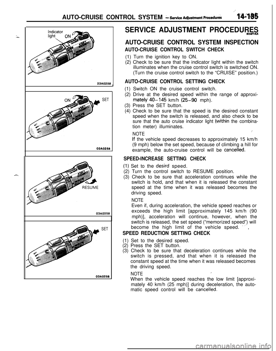
AUTO-CRUISE CONTROL SWITCH CHECK(1) Turn the ignition key to ON.
(2) Check to be sure that the indicator light within the switch
illuminates when the cruise control switch is switched ON.
(Turn the cruise control switch to the “CRUISE” position.)
AUTO-CRUISE CONTROL SETTING CHECK(1) Switch ON the cruise control switch.
(2) Drive at the desired speed within the range of approxi-
mately 40-145 km/h (25-90 mph).
(3) Press the SET button.
(4) Check to be sure that the speed is the desired constant
speed when the switch is released, and also check to be
sure that the auto cruise indicator light (tithin the combina-tion meter) illuminates.
NOTE1(
If the vehicle speed decreases to approximately 15 km/h
(9 mph) below the set speed, because of climbing a hill for
example, the auto-cruise control will be
cancelled.
SPEED-INCREASE SETTING CHECK
(‘1) Set to the desird speed.
(2) Turn the control switch to RESUME position.
(3) Check to be sure that acceleration continues while the
switch is hold, and that when it is released the constant
speed at the time when it was released becomes the
driving speed.
NOTEEven if, during acceleration, the vehicle speed reaches or
exceeds the high limit [approximately 145 km/h (90
mph)], acceleration will continue, however, when the
switch is released, the set speed (“memorized speed”) will
become the high limit of the vehicle speed.
’ ” ,
SPEED REDUCTION SETTING CHECK(1) Set to the desired speed.
(2) Press the SET button.
(3) Check to be sure that deceleration continues while the
switch is pressed, and that when it is released the
constant speed at the time when it was released becomes
the driving speed.
NOTEIWhen the vehicle speed reaches the low limit [approxi-
mately 40 km/h (25 mph)] during deceleration, the auto-
matic speed control will be
cancelled.
Page 590 of 1216
14-136AUTO-CRUISE CONTROL SYSTEM- Service Adjustment Procedures03AQ250
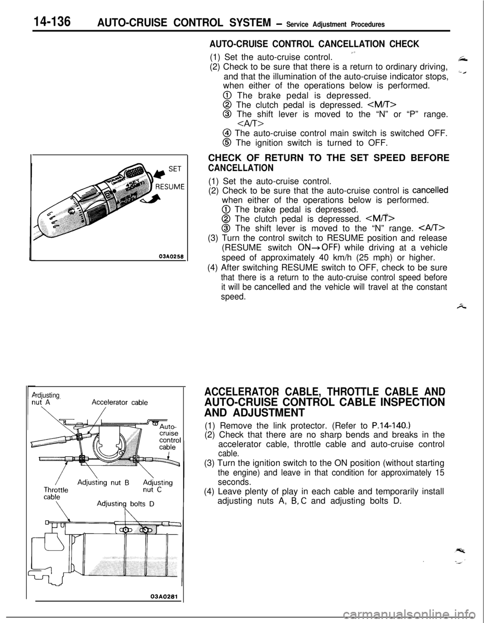
rdjusting
03A0281
AUTO-CRUISE CONTROL CANCELLATION CHECK(1) Set the auto-cruise control.
”(2) Check to be sure that there is a return to ordinary driving,
and that the illumination of the auto-cruise indicator stops,
‘cwhen either of the operations below is performed.
@ The brake pedal is depressed.
@ The clutch pedal is depressed.
@ The shift lever is moved to the “N” or “P” range.
aIT>
@ The auto-cruise control main switch is switched OFF.
@ The ignition switch is turned to OFF.
CHECK OF RETURN TO THE SET SPEED BEFORE
CANCELLATION(1) Set the auto-cruise control.
(2) Check to be sure that the auto-cruise control is
cancelledwhen either of the operations below is performed.
@ The brake pedal is depressed.
@ The clutch pedal is depressed.
@I The shift lever is moved to the “N” range. (3) Turn the control switch to RESUME position and release
(RESUME switch
ONdOFF) while driving at a vehicle
speed of approximately 40 km/h (25 mph) or higher.
(4) After switching RESUME switch to OFF, check to be sure
that there is a return to the auto-cruise control speed before
it will be
cancelled and the vehicle will travel at the constant
speed.
A
ACCELERATOR CABLE, THROTTLE CABLE AND
AUTO-CRUISE CONTROL CABLE INSPECTION
AND ADJUSTMENT(1) Remove the link protector. (Refer to P.14140.)
(2) Check that there are no sharp bends and breaks in the
accelerator cable, throttle cable and auto-cruise control
cable.(3) Turn the ignition switch to the ON position (without starting
the engine) and leave in that condition for approximately 15
seconds.(4) Leave plenty of play in each cable and temporarily install
adjusting nuts A,
B, C and adjusting bolts D.
Page 594 of 1216
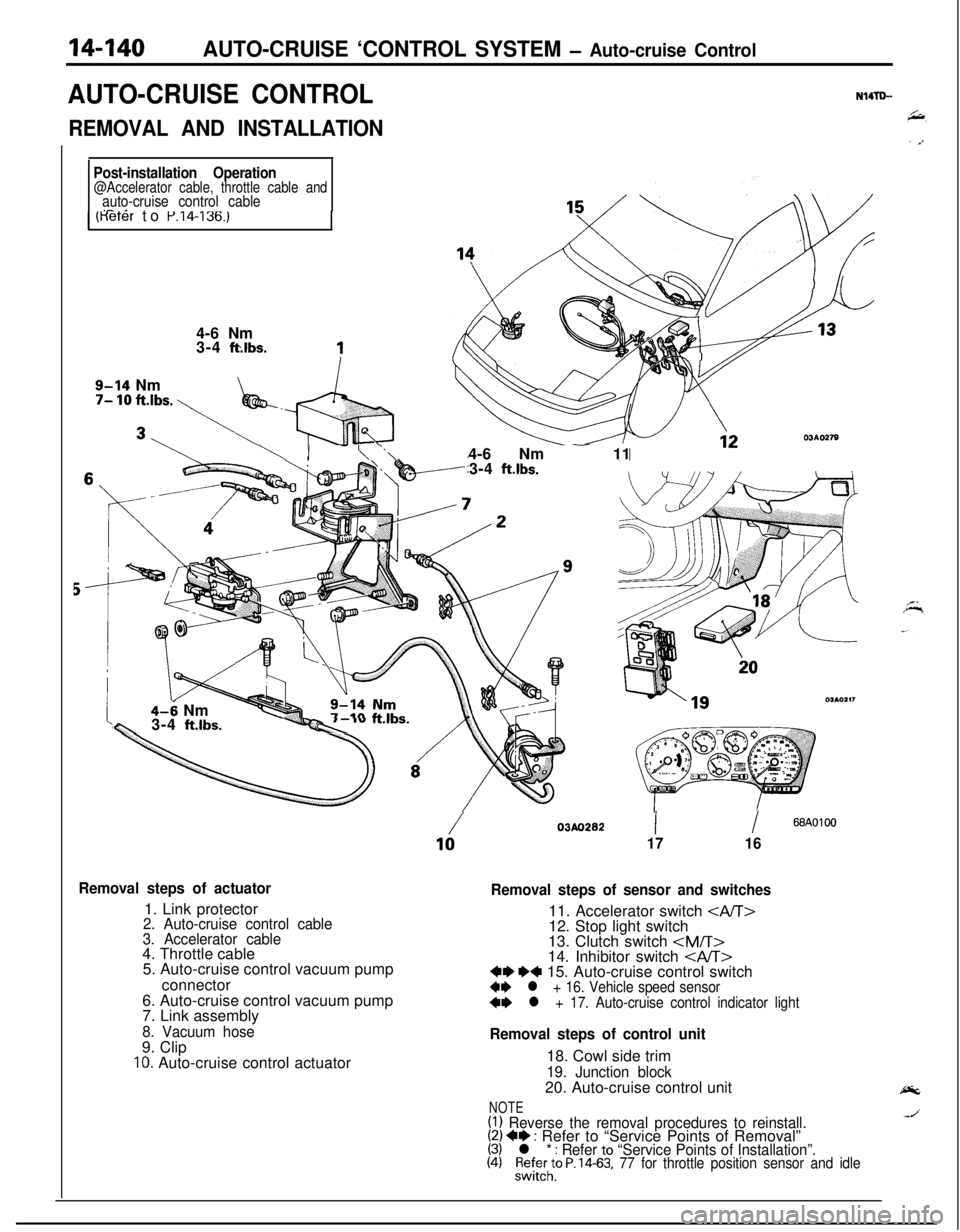
14-140AUTO-CRUISE ‘CONTROL SYSTEM - Auto-cruise Control
AUTO-CRUISE CONTROLN14TLL
REMOVAL AND INSTALLATION
Post-installation Operation@Accelerator cable, throttle cable andauto-cruise control cableI- _1 (Keter to P.14-136.)4-6 Nm
3-4
ft:lbs.
9-14 Nm7- 10 ft.lbs. \
\ I- \ ‘.\-4-6 Nm - 11
3-4 ft.lbs.
4-6 Nmw3-4 ft.lbs.--Qc ‘”
Removal steps of actuator1. Link protector
2. Auto-cruise control cable
3. Accelerator cable4. Throttle cable
5. Auto-cruise control vacuum pump
connector
6. Auto-cruise control vacuum pump
7. Link assembly
8. Vacuum hose9. Clip
IO. Auto-cruise control actuator
/03AO28210II68AOlOO
1716
Removal steps of sensor and switches11. Accelerator switch
12. Stop light switch
13. Clutch switch
Removal steps of control unit18. Cowl side trim
19. Junction block20. Auto-cruise control unit
NOTE(1) Reverse the removal procedures to reinstall.(2) +* : Refer to “Service Points of Removal”(3) l * : Refer to “Service Points of Installation”.(4)%l;;to P. 14-63, 77 for throttle position sensor and idle
Page 595 of 1216
AUTO-CRUISE CONTROL SYSTEM - Auto-cruise Control14-141
SERVICE POINTS OF REMOVAL?trmNWpBC
15. REMOVAL OF AUTO-CRUISE CONTROL SWITCHRefer to GROUP
8-Column Switch.
16. REMOVAL OF VEHICLE SPEED SENSORRefer to GROUP
8-Meters and Gauges.
17. REMOVAL OF AUTO-CRUISE CONTROL INDICATOR
LIGHTRefer to GROUP
8-Meters and Gauges.
INSPECTIONN14lDCEl Check the inner and outer cable for damage.
l Check the cable for smooth movement.
l Check the link protector for damage.
CHECKING THE AUTO-CRUISE CONTROL ACTUATORRefer to
P.14-138.
SERVICE POINTS OF INSTALLATIONN14TDDDD
17. INSTALLATION OF AUTO-CRUISE CONTROL INDICA-
TOR LIGHTRefer to GROUP
8-Meters and Gauges.
16. INSTALLATION OF AUTO-CRUISE CONTROL SWITCHRefer to GROUP
8-Column Switch.
15. INSTALLATION OF VEHICLE SPEED SENSORRefer to GROUP
8-Meter and Gauges.